The Sinclair Micro-FM
10 minute read
This post is part of the series 'Miniature Radios':
- Vicki 332
- World's First Transistor Radio
- The Sinclair Slimline
- The Sinclair Micro-FM
Sinclair's first FM radio
May 2025
In the December of 1965, two years after the launch of the Slimline regenerative Medium Wave receiver, Sinclair Radionics announced their first miniature FM receiver ... The Micro-FM, which at just shy of £6, was double the price of the original Slimline.
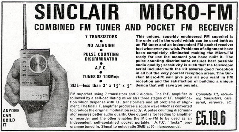
Up until now (December 1965), Sinclair's approach to advertising had been somewhat florid and exaggerated. The advert (above) for the Micro-FM is noticeably lacking in questionable claims relating to performance. However, the advert does boast about the use of 7 transistors and 2 diodes, a Pulse Counting Discriminator and A.F.C (automatic frequency control). It even hints that the (less than optimum) telescopic aerial might not yield best results in areas of marginal reception. But spot the mistake in the advert ... 'microseconds' should read 'microvolts'.
Incidentally, the practice of bragging about how many semiconductors are employed was a feature in adverts of the day. For example: I once bought a multi-band radio from a shop in the West End of Edinburgh. The advert had boasted that the radio employed what to me seemed a ridiculous number of transistors and diodes. On opening it up, I found a cluster of semiconductors in the corner of the large PCB. Turning the board over revealed that NONE of these devices had anything to do with the radio. They were likely all rejects simply added to the board in order to legitimise the semiconductor count.
But, returning to the Micro-FM ... According to Alfred Marks (Sinclair's publicist at the time), "it never worked. It did not have a proper aerial and just did not go."
So when I was presented with two Micro-FMs, and asked if I might get them working, I accepted the challenge. I had never heard of a Pulse Counting Discriminator, so I was eager to find out more.
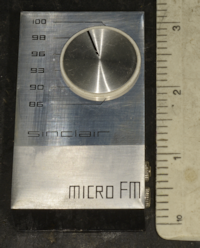
Using an identically sized box as the Slimline, the Micro-FM is much more aesthetically pleasing ... the brushed-aluminium front being a popular finish of the day ... and somewhat more professional-looking than the Slimline. However I do think that liberties were taken when describing the tuning knob as being of 'spun aluminium'. Such a description is normally applicable where the knob itself has been turned from solid aluminium. In this case the knob is a plastic disc with a self-adhesive brushed aluminium disc attached.
Rather than telescoping into the box, the aerial screws into a socket. There are two 2.5mm Jack Sockets ... one for the crystal earpiece which also serves to connect the battery when inserted ... the second socket is rather optimistically intended for connecting to an external device such as an amplifier.
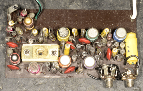
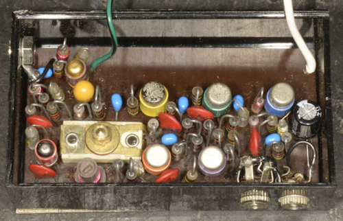
Above: The two Micro-FMs ... very similar but some subtle differences. I believe the one on the left to be slightly older as the two left-most transistors appear to be Philco M.A.T. devices. Also, there is a wire link on the PCB just to the left of the red ceramic disc capacitor just below the transistor with the orange sleeve. This link does not feature on the board on the right, and the location of the tiny polystyrene capacitor (C10) has been moved slightly. The items list shows C4 as 6.4uF. This is the blue miniature electrolytic capacitor in the photograph on the right. C4 on the board on the left was found to be 1uF. This change in value from 1uF to 6.4uF looks like a modification of the AFC time-constant.
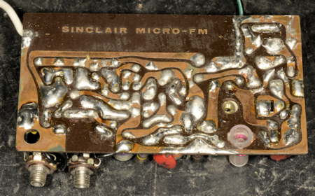
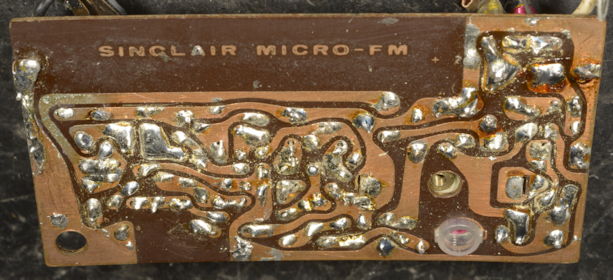
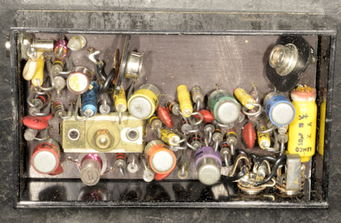
Above: Turning the boards over was very revealing. The Micro-FM was sold as a kit, there being no option to purchase it pre-assembled. It has to be said, that like the Slimline, the quality of the board is poor ... very thin Paxolin. But to be fair, fibre-glass boards were rare in those days. Interestingly, as with the Slimline that I worked on, the leads on the components on both boards had been cut incredibly short, such that the wires barely protruded through the holes. This wasn't a big issue on the board on the left where albeit generous, the quality of the soldering was generally good. The same could not be said for the soldering on the board on the right where the quality of soldering was simply atrocious. In many places the solder was adjacent to the wire. Many of the components were loose as a result. I ended up using solder-wick to remove most of the solder then re-soldering the joints. Afterwards, the board was 'washed' with 'Flux-Off' ... and in doing so, I learned something very interesting. I noticed that the black Micro-FM case looked as if it has been splashed with something. And that 'something' would not wipe off. It turns out that spray from the can of Flux-Off was the culprit, and the solvent that does a brilliant job of removing flux was reacting with the plastic box and literally melting it!! I have been using Flux-Off for may years and never encountered this before. What cheap plastic were Sinclair's boxes made from?
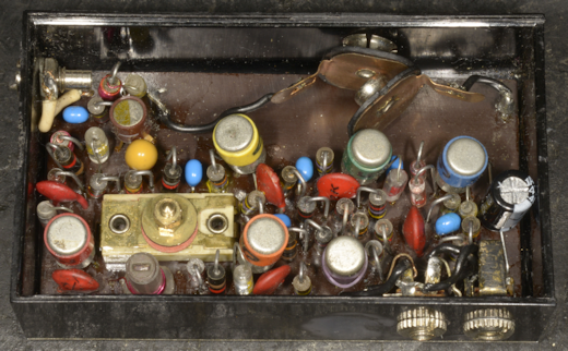
Above: The two refurbished Micro-FMs. All six 1uF electrolytics on each board were replaced with miniature ceramic discs of that value. The 6.4uF electrolytic in the AFC circuit (was 1uF on the older of the two) is now a 6.8uF Tantalum bead because that's all I had to hand. Finally the 50uF axial electrolyic across the battery has been replaced with a 47uF radial electrolytic.
On the subject of what exactly is a Pulse Counting Discriminator?, a trawl of the internet yielded much, too much in fact to cram into a couple of paragraphs. Suffice to say that it is a relatively simple and nifty way to demodulate frequency modulation. I suspect that since it is such a simple technique, there must be related short-comings for it not to be used more often. Here is a very well presented video which explains how a Pulse Counting Discriminator works.
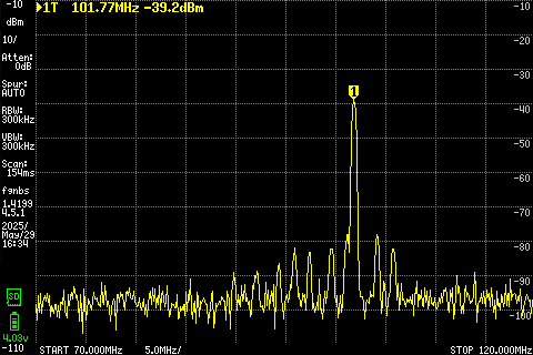 Left: A screen-grab on my TinySA Ultra showing the Local Oscillator of one of the Micro-FMs amidst a cluster of local Band II stations.
Unlike Medium Wave where there is precious little broadcast these days, Band II is awash with local stations. Both of the Micro-FMs worked straight away. Adjusting the local Oscillator such that the tuning is moderately accurate is a tad hit-or-miss on account of Sinclair's obsession with keeping costs down by using cheep 'tipper' trimmer capacitors when suitable miniature mylar variable capacitors were available. Audio quality is questionable but probably as good as you'll get from a crystal ear-piece. Alfred Marks' comment about the inadequacy of the aerial is correct. Ideally it should be twice the length ... but that would look stupid on something so tiny. Performance is highly dependent on location, aerial position and your own hand. But it works. Two out of two isn't bad. Maybe Alfred Marks' comment "it did not have a proper aerial and just did not go" reflected the lack of strong signals on Band II in 1965?
Post Script:
Sinclair described the Micro-FM as a 7-Transistor Superhet, and the manual states that the self-oscillating 'Frequency Changer' converts the received signal down to an Intermediate Frequency (I.F.) of 120KHz. Whilst many 'superhet' receivers use a final I.F. in the region of 350KHz to 470KHz, 120KHz might be though of as a bit low. But the Racal RA17 series of receivers uses a final I.F. of only 100KHz ... and then if you consider Racal's range of I.S.B. adapters where the final I.F. is 18KHz, then 120KHz doesn't sound so low after all. Exactly how this 120KHz I.F. is isolated, I have no idea, as there does not appear to be any obvious pass-band filtering after the mixer/oscillator ... and I have tried unsuccessfully to 'sniff out' a hint of 120KHz signal using my TinySA Ultra with the LNA enabled.
Sinclair also say that the design eliminates any aligning. To be honest, that claim is not accurate, as you still have to set the variable capacitor (C9) and inductor (L3) correctly for the receiver to cover the range of 86MHz to 100MHz. According to the manual, this would appear to be a purely mechanical procedure with a final optimisation from inductor L3.
We are told to screw the tuning knob/disc fully clock-wise until resistance is felt. The hole in the box doesn't quite match the hole in the board and it is questionable if the hole in the board is even centred on the screw-hole in the tipper capacitor. So what exactly is the source of physical resistance? We are then instructed to back the knob off by 'about' two turns. Does that sound a bit vague? Then we put a Paxolin washer followed by a brass washer over the protruding thread and then tighten it down with one of the two supplied brass nuts. So far, so good. Now we are told to screw on the second brass nut to lock the first nut. This lock-nut action is incredibly difficult to achieve since it requires you to prevent the first nut from turning clock-wise whilst tightening the second nut. Actually, correct application of a lock-nut requires the bottom nut to be turned anti-clockwise as the top nut is tightened. Given the restricted space and the use of 8BA nuts, this action is not easy.
The manual also tells us to set the core of L3 flush with the top of the coil former. Apparently, dial calibration should be approximate and that any discrepancy can be corrected by adjusting L3. The problem here is that L3 and C9 (the tuning capacitor) are highly interactive. Using my spectrum analyser, I was able to witness the range of the Local Oscillator over the 190 degrees between 86 and 100 on the scale ... and as the previous screen-grab shows, I could even see quite a few local Band II stations, so I had the advantage of modern technology on my side. By careful adjustment of L3 and the amount of compression on C9, I was able to achieve a fair compromise regards dial accuracy. I do feel for those who built this little radio 60 years ago.
My client informs me that he has three more Micro-FMs for me to look at!
Up until now (December 1965), Sinclair's approach to advertising had been somewhat florid and exaggerated. The advert (above) for the Micro-FM is noticeably lacking in questionable claims relating to performance. However, the advert does boast about the use of 7 transistors and 2 diodes, a Pulse Counting Discriminator and A.F.C (automatic frequency control). It even hints that the (less than optimum) telescopic aerial might not yield best results in areas of marginal reception. But spot the mistake in the advert ... 'microseconds' should read 'microvolts'.
Incidentally, the practice of bragging about how many semiconductors are employed was a feature in adverts of the day. For example: I once bought a multi-band radio from a shop in the West End of Edinburgh. The advert had boasted that the radio employed what to me seemed a ridiculous number of transistors and diodes. On opening it up, I found a cluster of semiconductors in the corner of the large PCB. Turning the board over revealed that NONE of these devices had anything to do with the radio. They were likely all rejects simply added to the board in order to legitimise the semiconductor count.
But, returning to the Micro-FM ... According to Alfred Marks (Sinclair's publicist at the time), "it never worked. It did not have a proper aerial and just did not go."
So when I was presented with two Micro-FMs, and asked if I might get them working, I accepted the challenge. I had never heard of a Pulse Counting Discriminator, so I was eager to find out more.
Using an identically sized box as the Slimline, the Micro-FM is much more aesthetically pleasing ... the brushed-aluminium front being a popular finish of the day ... and somewhat more professional-looking than the Slimline. However I do think that liberties were taken when describing the tuning knob as being of 'spun aluminium'. Such a description is normally applicable where the knob itself has been turned from solid aluminium. In this case the knob is a plastic disc with a self-adhesive brushed aluminium disc attached.
Rather than telescoping into the box, the aerial screws into a socket. There are two 2.5mm Jack Sockets ... one for the crystal earpiece which also serves to connect the battery when inserted ... the second socket is rather optimistically intended for connecting to an external device such as an amplifier.
Above: The two Micro-FMs ... very similar but some subtle differences. I believe the one on the left to be slightly older as the two left-most transistors appear to be Philco M.A.T. devices. Also, there is a wire link on the PCB just to the left of the red ceramic disc capacitor just below the transistor with the orange sleeve. This link does not feature on the board on the right, and the location of the tiny polystyrene capacitor (C10) has been moved slightly. The items list shows C4 as 6.4uF. This is the blue miniature electrolytic capacitor in the photograph on the right. C4 on the board on the left was found to be 1uF. This change in value from 1uF to 6.4uF looks like a modification of the AFC time-constant.
Above: Turning the boards over was very revealing. The Micro-FM was sold as a kit, there being no option to purchase it pre-assembled. It has to be said, that like the Slimline, the quality of the board is poor ... very thin Paxolin. But to be fair, fibre-glass boards were rare in those days. Interestingly, as with the Slimline that I worked on, the leads on the components on both boards had been cut incredibly short, such that the wires barely protruded through the holes. This wasn't a big issue on the board on the left where albeit generous, the quality of the soldering was generally good. The same could not be said for the soldering on the board on the right where the quality of soldering was simply atrocious. In many places the solder was adjacent to the wire. Many of the components were loose as a result. I ended up using solder-wick to remove most of the solder then re-soldering the joints. Afterwards, the board was 'washed' with 'Flux-Off' ... and in doing so, I learned something very interesting. I noticed that the black Micro-FM case looked as if it has been splashed with something. And that 'something' would not wipe off. It turns out that spray from the can of Flux-Off was the culprit, and the solvent that does a brilliant job of removing flux was reacting with the plastic box and literally melting it!! I have been using Flux-Off for may years and never encountered this before. What cheap plastic were Sinclair's boxes made from?
Above: The two refurbished Micro-FMs. All six 1uF electrolytics on each board were replaced with miniature ceramic discs of that value. The 6.4uF electrolytic in the AFC circuit (was 1uF on the older of the two) is now a 6.8uF Tantalum bead because that's all I had to hand. Finally the 50uF axial electrolyic across the battery has been replaced with a 47uF radial electrolytic.
On the subject of what exactly is a Pulse Counting Discriminator?, a trawl of the internet yielded much, too much in fact to cram into a couple of paragraphs. Suffice to say that it is a relatively simple and nifty way to demodulate frequency modulation. I suspect that since it is such a simple technique, there must be related short-comings for it not to be used more often. Here is a very well presented video which explains how a Pulse Counting Discriminator works.
Unlike Medium Wave where there is precious little broadcast these days, Band II is awash with local stations. Both of the Micro-FMs worked straight away. Adjusting the local Oscillator such that the tuning is moderately accurate is a tad hit-or-miss on account of Sinclair's obsession with keeping costs down by using cheep 'tipper' trimmer capacitors when suitable miniature mylar variable capacitors were available. Audio quality is questionable but probably as good as you'll get from a crystal ear-piece. Alfred Marks' comment about the inadequacy of the aerial is correct. Ideally it should be twice the length ... but that would look stupid on something so tiny. Performance is highly dependent on location, aerial position and your own hand. But it works. Two out of two isn't bad. Maybe Alfred Marks' comment "it did not have a proper aerial and just did not go" reflected the lack of strong signals on Band II in 1965?
Post Script:
Sinclair described the Micro-FM as a 7-Transistor Superhet, and the manual states that the self-oscillating 'Frequency Changer' converts the received signal down to an Intermediate Frequency (I.F.) of 120KHz. Whilst many 'superhet' receivers use a final I.F. in the region of 350KHz to 470KHz, 120KHz might be though of as a bit low. But the Racal RA17 series of receivers uses a final I.F. of only 100KHz ... and then if you consider Racal's range of I.S.B. adapters where the final I.F. is 18KHz, then 120KHz doesn't sound so low after all. Exactly how this 120KHz I.F. is isolated, I have no idea, as there does not appear to be any obvious pass-band filtering after the mixer/oscillator ... and I have tried unsuccessfully to 'sniff out' a hint of 120KHz signal using my TinySA Ultra with the LNA enabled.
Sinclair also say that the design eliminates any aligning. To be honest, that claim is not accurate, as you still have to set the variable capacitor (C9) and inductor (L3) correctly for the receiver to cover the range of 86MHz to 100MHz. According to the manual, this would appear to be a purely mechanical procedure with a final optimisation from inductor L3.
We are told to screw the tuning knob/disc fully clock-wise until resistance is felt. The hole in the box doesn't quite match the hole in the board and it is questionable if the hole in the board is even centred on the screw-hole in the tipper capacitor. So what exactly is the source of physical resistance? We are then instructed to back the knob off by 'about' two turns. Does that sound a bit vague? Then we put a Paxolin washer followed by a brass washer over the protruding thread and then tighten it down with one of the two supplied brass nuts. So far, so good. Now we are told to screw on the second brass nut to lock the first nut. This lock-nut action is incredibly difficult to achieve since it requires you to prevent the first nut from turning clock-wise whilst tightening the second nut. Actually, correct application of a lock-nut requires the bottom nut to be turned anti-clockwise as the top nut is tightened. Given the restricted space and the use of 8BA nuts, this action is not easy.
The manual also tells us to set the core of L3 flush with the top of the coil former. Apparently, dial calibration should be approximate and that any discrepancy can be corrected by adjusting L3. The problem here is that L3 and C9 (the tuning capacitor) are highly interactive. Using my spectrum analyser, I was able to witness the range of the Local Oscillator over the 190 degrees between 86 and 100 on the scale ... and as the previous screen-grab shows, I could even see quite a few local Band II stations, so I had the advantage of modern technology on my side. By careful adjustment of L3 and the amount of compression on C9, I was able to achieve a fair compromise regards dial accuracy. I do feel for those who built this little radio 60 years ago.
My client informs me that he has three more Micro-FMs for me to look at!