Decade Frequency Generator Type MA350B
35 minute read
July 2025
I have to admit that when I put the MA350B on the bench, I felt like I was embarking on uncharted territory. Rinus Jansen describes the MA350 as 'extremely complicated' and 'very difficult to repair'. The more I read the manual, the more I realised that the MA350 is not necessarily 'extremely complicate' but might be better described as being of an extremely 'clever' design. It does exactly what its name suggests, and achieves this without a single integrated circuit. Dating from 1967, it does however involve no less than 157 Silicon transistors, 5 Germanium transistors and 6 Tunnel Diodes! I didn't bother to count the numerous Silicon, Germanium and Varicap Diodes. However, the MA350 was not Racal's first Decade Frequency Generator ...


An interesting feature of the MA150 is that unlike its successors, frequency selection does NOT use switches, as each decade tunes continuously. This is more than likely why the MA150 proved difficult to maintain and thus lead to the introduction of the MA350. Speaking of which ...

Above: Here we have the MA350B. Like the MA79H in the previous article, it is destined for a client in New Zealand. Both units have an after-market Perspex-based Racal badge which may suggest that at some time they have passed through Telford Electronics. The fact that the lens on the 'Out Of Lock' light is green as opposed to red may indicate that the original red lens was damaged, and the only replacement available was green.


The Power supply in the MA350 is simplicity itself, comprising two somewhat similar regulator circuits ... one delivering +12V and the other -6V. The 12V supply is the more critical of the two since the switched resistor networks for the VCO circuits are connected across it. The -6V line is not so critical, but both supplies can be set precisely by way of multi-turn potentiometers. All four of the radial smoothing capacitors carried markings which suggested that they were checked or re-formed in 1972. That was 53 years ago, so I decided to re-stuff them rather than simply apply 240V mains and hope that they didn't go bang. A good decision, as the next photographs will suggest.

As can be seen in the photograph on the left, it looks like this capacitor had been getting very hot. All four of the radial smoothing capacitors exhibited this kind of damage.


All ten of the original 'top-hat' 60's rectifiers looked terrible. They were so corroded that it was not possible to read any of the identification marks ... thus they too were replaced.


C8, 1000uF/50V, originally mounted off the board, was replaced with a smaller and lighter capacitor which was able to be mounted directly onto the board. Throughout the MA350, Racal made use of small axial, tubular tantalum capacitors. Although these differ from the notoriously unreliable bead-type tantalum capacitors. It was quite revealing to learn that even today (2025), that the life expectancy of any Tantalum capacitor is still only around 20 years. Thus, the decision was made to replace these with aluminium types where possible ... as can be seen in the above photographs.

But where are the two 2N3055 series pass-transistors? The circuit diagram shows a dotted line around most of the components associated with the regulators, so we can assume that this indicates the components on the board. The 2N3055s are out with this boundary. They are in fact tucked away on the main chassis just behind the front panel, beneath the panel meter. Normally, such transistors are to be found on finned heat-sinks. However, under suitable mounting conditions, the 2N3055 is capable of dissipating 115W. Given that the fuses for the each of the two supply rails are 2.5A, the maximum combined power dissipation could be in the region of 45W, assuming both supplies draw 2.5A, which they don't. So, they're quite safe where they are ... just not very convenient.

This MA350 was supplied without the SA510 Internal 1MHz Frequency Standard. However, this is not an issue as it will be used in conjunction with an MA259 Frequency Standard.

As with all power supplies where the smoothing packs have been replaced, I initially powered it up via a variac as a precaution. Nothing went bang ... that's always a good sign. I connected the 5MHz output from my MA259 to the External Frequency Standard input on the MA350, and it did appear that the MA350 was in fact working. The four static outputs, 1MHz, 1.7MHz, 200KHz and 100KHz were all present and correct. Even the synthesiser output was present and stable ... although this turned out to be a co-incidence ...

As the photograph above shows, the MA350B can support either two RA117 receivers, two MA79H Transmitter Drive Units, or one of each, with all signals derived from a single Reference Standard ... which, thanks to some very clever analogue circuitry, can be either 100KHz, 200KHz, 1MHz or 5MHz.
As hinted earlier, the synthesiser output 'appeared' to be working but quickly proved to be purely co-incidence. Selecting random decades did in fact reveal that there were issues. The 100KHz decade consistently would not lock when set to 2, 3 and 7. The 10KHz decade would not lock on 2 or 3 and the 1KHz decade failed to lock when set to 2. There's clearly a bit of a theme here.
Over the years, synthesisers have evolved, with integrated circuits then microprocessors playing a large part in later years. I won't even attempt to detail the different 'flavours' of synthesis that have come about. The MA350 is an analogue synthesiser, relying on clever arithmetic rather than logic. In order to repair this one, I was going to have to get my head around the processes involved.
Fortunately the MA350 can be divided into five building blocks (or modules) which Racal, for some reason chose to identify with cryptic initials rather than implicit descriptive names. These are:
CRXJ - Takes whatever Frequency Standard is used and generates the following signals ... 100KHz, 200KHz, 300KHz and 1MHz. It also provides the triangle-wave for the Hunt Generator and the 300KHz to 400KHz signal for the Interpolation Oscillator.
CHG - The Harmonic Generator. Provides ten independent outputs, 100KHz spaced, between 2.7MHz and 3.6MHz ... derived from the 100KHz signal.
CMJ - Generates the 1.7MHz output and provides a buffer amplifier for the 200KHz output. Also generates a 400KHz signal from which a 7.6MHz harmonic is derived. This is then mixed with one of the ten outputs (2.7MHz to 3.6MHz) from the Harmonic Generator to produce a signal between 4.0MHz and 4.9MHz.
CDDJ/CDDJ - The 100Hz and 1KHz decades.
CDDJ/CDJ - The 10KHz and 100KHz decades.
The manual describes the synthesiser part of the MA350 under two headings ... and this goes some way towards decoding the cryptic initials ...
The Reference Frequency Section consists of CRXJ, CHG and CMJ, where RX implies reference, HG is obviously Harmonic Generator and MJ might refer to Multiplier.
The Decade Generators are CDDJ (of which there are three) and CDJ (the 100KHz decade). In this category DD implies Decade Divider since the output of the first three is subsequently dived by 10 and passed up the chain. The D in CDJ simply implies decade as the output is not divided by ten. This process will be described in detail later.
So far, so good ... And the letter C undoubtedly means circuit. But I have no idea what J means.

The decade generators are numbered from least significant digit to most significant digit, i.e. CDDJ1 is 100s of Hertz, CDDJ2 is the KHz decade and CDDJ3 is 10s of KHz. CDJ provides the 100s of KHz. With reference to the diagram above ...
When I saw the name Quadricorrelator, I thought it was a made up name, like the Swingometer in the MM420 amplifier. However, it isn't, and a trawl of the Internet will yield several papers, some as recent as the 1990s, on the use of Quadricorrelators. The manual gives a very detailed description of how everything works.
Here is the simplified version ...
The idents, CDD1 thru' CDD6 identify the individual boards that make up the CDDJ unit. For some reason these idents differ from those on the actual schematic, but I will refer to those in the simplified diagram for the purpose of explaining how it works. Oscillator CDD1 is a VCO which is initially pre-tuned using a voltage derived from the bias chain selected by SW1. The selected voltage/bias is such that the oscillator is roughly set to a frequency 300KHz higher than that selected by SW2, which is applied to Mixer CDD2. Thus, the output of Mixer CDD2 is 300KHz. This is fed to both the Phase Comparator CDD4 and the Quadricorrelator CDD5. A triangle-wave Hunt signal from the CRXJ Reference Module is applied via RLA and 'takes control' of the VCO. For CDDJ1, the Reference Frequency is the 300KHz generated in the CRXJ Reference Module, and is applied to both the Phase Comparator and the Quadricorrelator. The latter is really just a phase-controlled switch which removes the Hunt signal when both inputs are in-phase. When this happens, VCO CDD1 is then under the control of the error signal from the Phase Comparator CDD4. The output of the VCO is also fed to Divider CDD6 which provides the Reference signal for CDDJ2. Consequently, CDDJ2 provides the Reference for CDDJ3, which ultimately provides the the Reference for CDJ.
As can be seen, there are actually no less than three tuning mechanisms involved in setting and locking each of the decades ... but it works!
The final Decade Generator CDJ operates in a slightly different way ...

Since the output of the CDJ unit must be in the range 3.6MHz - 4.6MHz, its oscillator output is NOT divided by 10. Thus, the oscillator must operate over this range as opposed to the 3MHz - 4MHz range of the CDDJ Decade Generators. It is therefor necessary to provide a different range of control frequencies and coarse VCO tuning voltages. The control frequencies are generated by passing the 2.7MHz - 3.6MHz selection from CHG to the CMJ module where by mixing and filtering the new range of 4.0MHz - 4.9MHz in 100KHz steps is produced.
Note that whereas in CDDJ1-3 the VCO runs at ~300KHz higher than the control frequency from CHG, In the CDJ unit, the VCO runs at the desired output frequency and it is the Control Frequency from the CMJ module that is ~300KHz higher. Otherwise, the operation is similar to the CDDJ.
The following modified table from the manual shows the arithmetic flow ... simple when you know how!

So that's how it works ... only the MA350B on my bench had at least one fault, and probably needed a bit of TLC.

Left: The rear of the MA350B with top and bottom covers removed. The former is somewhat flimsy and someone had clearly (inadvertently) used it as a handle and thus the aluminium had snapped at the back left corner. The Plessey mains connector supplied had incorrect 'keying' and did not mate with the chassis connector, so the first thing I had to do was dismantle the free socket and move the insert round to match the chassis plug ... easy, but time consuming. After that it was a simple case of making up a mains cord.
As can be seen, the die-cast aluminium chassis is very substantial, contributing to the unit's weight of 27.3Kg ... just slightly lighter than the RA117 or MA79.


Admittedly, the underside looks a lot cleaner than the upper side. Also, going by the hand-written identification on the plug-in modules, it looks like the modules are not all 'original', and might have come from different MA350s.
All the 'magic and wizardry' takes place in the four chunky modules. Seen from the top, these are the CMJ module on the left, followed by the CDDJ/CDJ module, the CDDJ/CDDJ module then the CRXJ module.

Note that the four Decade switch shafts have universal joints at either end. This is not just so any misalignment from front to back can be catered for. Once all six Allen screws supporting the casting that supports the rear switches are removed, it is possible, with care, to ease the bank of switches up and out in order to access wiring. That's the theory. It isn't quite that simple as there is a distinct lack of service loops, which will be explained in due course.
After generously treating all the switch wafers to a blast of De-Oxit, the MA350 was almost but not quite fully functional. There was still something odd regards the relationship between the 100KHz and 10KHz Decades. But not only that, it was no longer locking if any of the decades were set to 0 (zero).
 Left: The easiest initial test to carry out is to verify the bias voltages applied to the four VCOs. The voltages for the CDDJ units were all well within spec. This is the resistor network on the switch wafers on the left. However the voltages applied to the CDJ unit were within spec. too, but all elevated to the upper limit. This was found to be the result of R64 (1K) (far-left on circuit board) being high at 1.01K. This was replaced with a resistor measuring 1.000K and all voltages dropped to mid-band. However the odd relationship between the two decades remained. Essentially the 100KHz decade would consistently NOT lock on 9 if the 10KHz decade was on 7 or 9. It was looking like a full alignment of the MA350 might be necessary in order to track down the anomaly.
Above: Harmonic Generator Module CHG with an inset on the left showing the driver board with the tubular Tantalum capacitor replaced with an aluminium type.
When you work on Racal kit from the 1950s and 1960s you realise just how fortunate we are nowadays in terms of test equipment. Note how often signal measurement asks for a Valve Voltmeter, and in which case the reading is r.m.s. This is because bench oscilloscopes of the day generally did not have enough bandwidth. I have a Racal-Dana 9901A True R.M.S. Voltmeter, but its input is 50-ohms, so in many cases I measure the amplitude on my oscilloscope and divide by 2.2. We take for granted that our general-purpose oscilloscope will have a bandwidth of at least 100MHz, that RF signal generators are all synthesised ... and the advent of small inexpensive spectrum analysers makes it possible to see in real-time what's there and what isn't ... and that's how I realised something wasn't right with the 2.7MHz output from the Harmonic Generator ... the level at the CDDJ was at least 20dB down on all the other outputs. Hence the issue with position zero on all decades.
The manual for the MA350 mentions extension cables and a card extender for diagnostic purposes. To be honest, you don't need the recommended extension cables for the four plug-in modules since there is enough existing cable length to run each module outside the rack by turning the MA350 on its side and reconnecting the module under test on the underside.
The CHG module (Harmonic Generator) can be tested out of the chassis but the loading on the outputs will be off, hence the need for a card-extender. However, this wouldn't be necessary if there was a milled aperture in the rear wall of the main casting which would allow direct access to each of the ten tuneable output transformers (see the image above). The 'Fundamental' for most of what goes on in the MA350 is 100KHz, which is derived from whatever the chosen Frequency Standard is. This is similar to the MA79 where the 14th and 16th harmonics of 100KHz are used to produce signals at 1.4MHz and 1.6MHz. The MA350 takes this even further by using a Pulse Generator as the source of harmonics all the way up to 3.6MHz ... the 36th harmonic of 100KHz. The ten output boards all have a very narrow band-pass filter on the input. Each filter consists of two crystals, which in conjunction with three capacitors is thus tuned to pass only the desired frequency ... in this case 2.7MHz up to 3.6MHz in 100KHz steps.

With the CHG unit on the bench, and with 100KHz supplied from my Adret 7100D, I checked all the RF outputs on my vintage Tektronix 7603. All the waveforms were within spec. in terms of amplitude, and my Racal-Dana 9916 confirmed that in each case the frequency was 'spot-on'. However the waveform of the 2.7MHz output was what I would describe as 'woolly' ... a bit fuzzy ... not crisp and clear. One of the output pins was bent almost horizontal, and straightening it caused it to snap off. A quick check with a multimeter revealed that the secondary of T1, the output transformer, was intermittently open-circuit. As can be seen from the image on the right, the transformer is 'potted'. Fortunately I managed to very carefully peel away the rubber to gain access to the solder spills and flow some solder into each hole. This proved successful. The signal is now clean, the level at 2.7MHz is now on a par with all the others, and I have confidence that the joints are good.
As an aside: Something worth noting here is that the driver stage (actually the harmonic generator itself) employs a Tunnel Diode ... a Philco 1N3562. This is the small gold TO-18 device in the two photographs above. There are five more of these devices in the MA350 ... one in each of the CDDJ modules, and two in the CMJ module. Tunnel Diodes tend to be used in circuits where very fast rise (and or) fall times are required. As such they are ideal for generating harmonics, since mathematically speaking, these incredibly fast edges are rich in harmonics. Where Tunnel Diodes tend to be used at relatively low frequencies, Step-Recovery-Diodes or SRDs were often used to generate harmonics up to several GHz. Tunnel Diodes have been in production since the early 1960s, and although modern technology has seen them superseded, they are still manufactured in small numbers today, and generally NOT in TO-18 format. Expect to pay upwards of £10 for one today.
Although the Harmonic Generator was now working properly, there was still the issue with the peculiar relationship between the 100KHz and 10KHz Decades. To be honest, I had not expected the repair to the 2.7MHz board to change change this ... but at least there was now one less fault to locate. I had already confirmed correct operation of the CRXJ Reference Module. Below are some photographs on what's inside, and what's been replaced.


Above: Clock-wise from bottom-left: Limiter (CRX1), 1MHz Divider (CRX2), 200KHz Divider (CRX3), 100KHz Divider (CRX4), 1MHz Multiplier (CRX6).
The dividers are transistorised incarnations of the valve-based Regenerative Dividers employed in the RA17, RA117 and MA79 etc.


Above: Clock-wise from bottom-left: 200KHz Multiplier (CRX5), Interpolation Oscillator (CRX12), 300KHz Multiplier (CRX10), Hunt Generator (CRX11), Relay A.
Historically, bead-type tantalum capacitors have a history of unreliability. There is an old saying ... 'Never trust a tant, especially a blue one'. When I worked for Racal (1979 - 1992), we used blue 'tants' and the small silver tubular ones. That was many years ago. I have two MA350s in for repair/refurb. As previously mentioned, this one is destined for a client in New Zealand. The other will be going to a UK-client who has much experience with servicing UK manufactured military electronics that is now several decades beyond manufacturer care. I asked him what his policy would be regards the tubular 'tants'. Reinforcing the view that they have a reliable life of only 20 years, he said "replace them". So that is what I have been doing. However, for some reason it isn't possible to get axial aluminium electrolytics small enough to fit where some of the smaller tubular tants came out. However, smaller radial aluminium electrolytics are available, and fortunately they are short enough to fit upright on the boards.


Above: Anti-clockwise from top-left: Oscillator (CDD1), Mixer (CDD2), Band-Pass Filter (CDD3), Phase Comparator (CDD4), Quadricorrelator (CDD5), Divide by 10 (CDD6). All three CDDJs are identical. The 100Hz and 1KHz CDDJs are in the module adjacent to the CRXJ module. As far as I could ascertain, both of these were working perfectly (at this point), even the 10KHz CDDJ in the CDDJ/CDJ module appeared good.


Above: Anti-clockwise from top-left: Oscillator (CDJ1), Mixer (CDD2), Band-Pass Filter (CDD3), Phase Comparator (CDJ4), Quadricorrelator (CDJ5), and Low Pass Filter (CDJ5).
Note how the plate mounting the two connectors is was initially bent. Interestingly, this particular module (CDDJ/CDJ) bore a sticker with the word 'Rejected' written on it. I believe it was dated 1997. This added weight to my theory that this MA350 might have been put together from parts from other MA350s.
It will be noted that on each of the four Phase Comparator boards there is a tubular capacitor that has not been replaced. This is C16 (16uF), a non-polarised capacitor. I suspect it is nothing more than two 32uF tantalum capacitors connected back-to-back inside a common (isolated) metal tube. Not being able to identify a suitable and affordable alternative, I chose to not replace these. On the four Quadricorrelator boards, there are two polyester 100nF capacitors, the sort that we used to say looked like sweeties. The MA350 has more than a few of these, but on the Quadricorrelator, C42 and C43 are too large by about 5mm. Thus in each case, one of the legs is bent right under the capacitor so as to fit the holes in the board. I used to think these 'sweeties' were great, and I loved it when as a teenager, I bought bags of miscellaneous capacitors that contained these. Nowadays I am more likely to rip them out of units as my experience in recent years is that under certain stresses, one or other of the legs very often rips off. In my mind, with one of the legs bent in such an extreme way, the integrity of C42 and C43 was suitably compromised to warrant replacement. Thus, on each of the Quadricorrelator boards, these were replaced with physically smaller capacitors.
We still have the CMJ module to discuss, but up to this point I was more or less happy with the way things were going, even though the 100KHz decade would consistently NOT lock if the 10KHz decade was set to 9, and would occasionally intermittently fail to lock when it (100KHz decade) was set to other settings ... and the condition was showing signs of getting worse. This was interesting, and the manual suggested that this condition might be the result of dirty switch contacts. Which brings us back to the feature where the switch wafers on the end of the decade shafts can be raised up and out of the channel ... for cleaning, perhaps?
I have no less than four spectrum analysers. My Systron Donner covers 10MHz up to 12.4GHz. The spectrum analyser function on my HP8920 is good from below 100KHz up to 1GHz. My TinySA hand-held analyser is good from several KHz right up to just shy of 6GHz ... and can go higher with reduced sensitivity. But when I need a tracking Generator, I turn to my Rigol DSA-815TG which will go down to around 80KHz and up to 1.5GHz.
As previously described, the CDJ module which provides the 100KHz decade works in a slightly different way to the three previous decades. Although the output of the Harmonic Generator (CHG) is still used, instead of going directly to the CDJ Mixer stage, it is diverted to the CMJ module where it is mixed with 7.6MHz to become a range of 100KHz steps between 4.0MHz and 4.9MHz. Using the Rigol Spectrum Analyser to monitor this signal at the input to the CDJ mixer, I noticed that the level varied dramatically over the specified range. It generally varied by about 10dB between 4.0MHz and 4.8MHz, but was at least 20dB down at 4.9MHz. Since the output of the the CMJ is a Band-Pass filter covering 4.0MHz to 4.9MHz, I figured that investigating this filter was probably a good place to start. The manual does not give any details, like pass-band ripple, or 3dB or 6dB points. It even states that adjustment is beyond the scope of a 'normal repair depot' ... hmmm? Sounds a bit like the 40MHz filter in the RA17 ... so shouldn't be problem then.


Above: No Tantalum capacitors to replace in the CMJ.
On Side 1: Anti-clock-wise from bottom left: Pulse Generator (CMJ6), Band-Pass Filter (CMJ11), Amplifier (CMJ10), Buffer Amplifier (CMJ9), Mixer (CMJ8).
On Side 2: Clock-wise from top-left: 200KHz Amplifier (CMJ2), 7.6MHz Filter (CMJ5), Unused space, DC Filter (CMJ3), 4.0MHz - 4.9MHz Band-=Pass Filter (CMJ4).
This filter is indeed very similar to the 40MHz filter in the RA17 in that the 'elements' are all interdependent, so all adjustments need to be small and incremental. It had obviously been tweaked. The excessive pass-band ripple was very obvious and it tended to favour the lower frequencies. It took me a few minutes, but using the Tracking Generator in the Rigol, I eventually managed to minimise the insertion-loss, achieve a pass-band ripple of no more than 2dB and keep the lower and upper limits of 4.0MHz and 4.9MHz within the pass-band. This last part took considerable care since the response rolls off dramatically below 4.0MHz and above 4.9MHz. Satisfied with the filter response, I re-tested the MA350 and found that although the intermittent failure to lock issue was now resolved, thanks to reducing the pass-band ripple in the filter, the 100KHz decade was still not locking as before. However, it now also failed to lock when set to 2. In fact, ALL the other decades were now NOT locking at position 2. This indicated to me that something was not right with the 2.9MHz signal from the Harmonic Generator. This was confirmed when I monitored the input to the mixer in the CDJ module. When the decade was set to 2, there was no signal at 4.2MHz, or at 2.9MHz at the other three CDDJs.
This told me that there was a break in continuity between the CHG module and the bank of switch wafers in the channel above (or below, if the MA350 is the right way up!) the edge connector that the CHG slotted into. The bad news was that the wafer contact was likely one furthest away, i.e. at the bottom of the channel, and with all that coax adorning the switches, it was impossible to even see the edge connector. The good news though was that thanks to the universal joints on the switch shafts, I should be able to 'hinge' the entire wafer assembly out of the channel and see what was amiss.

However it wasn't that easy. Yes, the six Allen screws were easy enough to remove, but getting the assembly to move was another story. When I finally managed to tilt it, it was only by a few degrees. The problem was two-fold. First, there is a hole through which three wires head off to the PSU and a single coax disappears into a tight bundle of similar blue coax. It was necessary to break into the wire harness in the PSU to get some more movement. That worked. However the second issue was a total lack of service loops between the edge connector and the switch wafers. I have no idea how this was assembled!
With the aid of a second pair of hands to hold the wafer assembly out of the way. I was able to identify the offender. It would appear that the coax to pin 5 was completely disconnected ... not broken. I am sure it had barely seen any solder. It wasn't easy, but I was able to push it back into the hole and then solder it properly.
With this repair accomplished, the wafer mechanism was eased back into place (not an easy task, I may add) and the MA350 re-tested. The issue with lack of lock at position 2 on all decades was resolved. Now all that remained was to figure out why the 100KHz decade would not lock when the previous decade was set to 8 or 9. By now I had a good idea what the problem was.
The final circuit in all three CDDJ modules is a Dive-By-10 circuit which provides the Reference for the next Decade Divider. This particular Divider differs from the other dividers which are of the regenerative type. This divide-by-10 is much more sophisticated and clever in that it uses a Tunnel Diode Oscillator where T8 is tuned to roughly one fifth of the 3MHz - 4MHz output from the VCO (CDD1). It is then fine-tuned by the output of the Phase Comparator (CDD4). This way the Tunnel Diode Oscillator tracks the VCO, but at one fifth the frequency. Transistor VT19 amplifies the output of the Tunnel Diode Oscillator, while T9 is tuned to respond to frequencies between 600KHz and 800KHz. T10 is tuned to respond to frequencies between 300KHz and 400KHz. The non-linear nature of diodes MR14-MR17 produces the sum and difference of these signals. The mixer is self-inducing since any impulse in the secondary of T10 will result in regenerative feedback from VT20 via C51, which maintains the mixing process. VT21 is the final stage of amplification. I trust this makes sense.
While using the Rigol Spectrum Analyser to observe the output of this divider (output of CDDJ3) while the 10KHz decade was set to 0 through to 9, I noticed that while the output level was fairly constant for settings of 0 to 7, it dropped off about 6dB on 8 and almost 20dB when set to 9. All that was required was a very minor tweak, about one quarter turn of T10 to bring the levels up at the high end of the scale. In short, T10 was tuned a wee bit low. With T10 re-tuned, I re-tested the MA350 ... BINGO! The MA350B now locks on every setting. No, I can't say that, I don't have time to do that! All four decades now flawlessly lock on every setting, and the output is a lovely rock-steady Sine Wave.

Above: The fully functional MA350B, complete with correct Red Out Of Lock lens. When re-fitting the top and bottom covers, I discovered that this MA350 must have been dropped at some point. The bottom right corner of the front panel isn't true. It has been bent slightly, then imperfectly straightened. Attempting to correct this aberration would only further damage the paint in that area. The bottom cover had clearly received a hefty blow, such that it was no longer flat. The thin aluminium had stretched, and no amount of bending was ever going to make any difference ... unless you know a panel beater! This was the reason why the connector panel on the CDJ module was bent.

Above: Just for fun, I connected the MA350B up to an RA1218. Here, the MA350B is supplying three inputs ... the 2nd VFO, the 3rd VFO (1.7MHz) and the 1MHz signal. It was very reassuring to see that the Nixie display mirrored the MA350B settings.
Finally: One feature of the MA350 that has not been discussed is the Interpolation Oscillator. The control for this is the one with the round knob and the graduated scale behind the crescent window. Strictly speaking, this control is ONLY relevant when the MA350 is providing the 2nd VFO for an RA117. Its purpose is for honing the output frequency of the MA350 to the precise frequency of a received signal. The Interpolation Oscillator can therefore be used to assist in setting the 1KHz, and 100Hz decades in turn. It is set up like this ... These two decades are each set in turn so that the red pane is visible in the window. This action causes the scale for the Interpolation Oscillator to illuminate. The 100KHz and 10KHz decades are set for a frequency close to the desired frequency and the receiver BFO is switched on. Then starting with the 1KHz decade, the Interpolation Oscillator is tuned until a zero-beat is heard on the receiver. The reading on the scale is noted and the 1KHz decade is set to the most significant digit. i.e. if the reading is 38, the decade should be set to 3. The operator then moves on to the 100Hz decade and repeats the process, setting the 100Hz decade to the appropriate setting. Should it be necessary, the final switch, to the left of the Interpolation Oscillator control, can be used to further fine tune the receiver to within 1Hz, in which case that two-position switch should be left with the red pane visible.
Thus, the Interpolation Oscillator provides three levels of variation ... 10KHz, 1KHz and 100Hz.
N.B. ... The MA350 will NOT lock unless ALL the decades are set to a valid integer i.e. 0 to 9.
MA150 with matching PSU.
That accolade falls to the MA150 pictured on the left. This behemoth first appeared in 1963 and was completely valve-based. The three-decade frequency generator involves no less than 41 valves and the separate power supply, a further 12!
Like its successor, the MA350, it was intended to augment the RA117 and MA79. In the form of the MA150A, its output range was 3.601MHz to 4.600MHz with an additional output at 100KHz. The MA150C had no 100KHz output.
The image on the right shows an RA220 Receiving Terminal comprising RA117, MA197, RA218 and MA150.
RA220 receiving Terminal.
An interesting feature of the MA150 is that unlike its successors, frequency selection does NOT use switches, as each decade tunes continuously. This is more than likely why the MA150 proved difficult to maintain and thus lead to the introduction of the MA350. Speaking of which ...
MA350B Ser. No.359 as received.
Above: Here we have the MA350B. Like the MA79H in the previous article, it is destined for a client in New Zealand. Both units have an after-market Perspex-based Racal badge which may suggest that at some time they have passed through Telford Electronics. The fact that the lens on the 'Out Of Lock' light is green as opposed to red may indicate that the original red lens was damaged, and the only replacement available was green.
Rectifiers and smoothing.
PSU underside.
The Power supply in the MA350 is simplicity itself, comprising two somewhat similar regulator circuits ... one delivering +12V and the other -6V. The 12V supply is the more critical of the two since the switched resistor networks for the VCO circuits are connected across it. The -6V line is not so critical, but both supplies can be set precisely by way of multi-turn potentiometers. All four of the radial smoothing capacitors carried markings which suggested that they were checked or re-formed in 1972. That was 53 years ago, so I decided to re-stuff them rather than simply apply 240V mains and hope that they didn't go bang. A good decision, as the next photographs will suggest.
A rather suspicious looking mess.
As can be seen in the photograph on the left, it looks like this capacitor had been getting very hot. All four of the radial smoothing capacitors exhibited this kind of damage.
New 1500uF capacitor.
New rectifiers.
All ten of the original 'top-hat' 60's rectifiers looked terrible. They were so corroded that it was not possible to read any of the identification marks ... thus they too were replaced.
Regulator board before.
Regulator board after.
C8, 1000uF/50V, originally mounted off the board, was replaced with a smaller and lighter capacitor which was able to be mounted directly onto the board. Throughout the MA350, Racal made use of small axial, tubular tantalum capacitors. Although these differ from the notoriously unreliable bead-type tantalum capacitors. It was quite revealing to learn that even today (2025), that the life expectancy of any Tantalum capacitor is still only around 20 years. Thus, the decision was made to replace these with aluminium types where possible ... as can be seen in the above photographs.
2 x 2N3055
But where are the two 2N3055 series pass-transistors? The circuit diagram shows a dotted line around most of the components associated with the regulators, so we can assume that this indicates the components on the board. The 2N3055s are out with this boundary. They are in fact tucked away on the main chassis just behind the front panel, beneath the panel meter. Normally, such transistors are to be found on finned heat-sinks. However, under suitable mounting conditions, the 2N3055 is capable of dissipating 115W. Given that the fuses for the each of the two supply rails are 2.5A, the maximum combined power dissipation could be in the region of 45W, assuming both supplies draw 2.5A, which they don't. So, they're quite safe where they are ... just not very convenient.
No Internal Frequency Standard.
This MA350 was supplied without the SA510 Internal 1MHz Frequency Standard. However, this is not an issue as it will be used in conjunction with an MA259 Frequency Standard.
SA510.
As with all power supplies where the smoothing packs have been replaced, I initially powered it up via a variac as a precaution. Nothing went bang ... that's always a good sign. I connected the 5MHz output from my MA259 to the External Frequency Standard input on the MA350, and it did appear that the MA350 was in fact working. The four static outputs, 1MHz, 1.7MHz, 200KHz and 100KHz were all present and correct. Even the synthesiser output was present and stable ... although this turned out to be a co-incidence ...
MA350B Rear Panel Input/Output ports.
As the photograph above shows, the MA350B can support either two RA117 receivers, two MA79H Transmitter Drive Units, or one of each, with all signals derived from a single Reference Standard ... which, thanks to some very clever analogue circuitry, can be either 100KHz, 200KHz, 1MHz or 5MHz.
As hinted earlier, the synthesiser output 'appeared' to be working but quickly proved to be purely co-incidence. Selecting random decades did in fact reveal that there were issues. The 100KHz decade consistently would not lock when set to 2, 3 and 7. The 10KHz decade would not lock on 2 or 3 and the 1KHz decade failed to lock when set to 2. There's clearly a bit of a theme here.
Over the years, synthesisers have evolved, with integrated circuits then microprocessors playing a large part in later years. I won't even attempt to detail the different 'flavours' of synthesis that have come about. The MA350 is an analogue synthesiser, relying on clever arithmetic rather than logic. In order to repair this one, I was going to have to get my head around the processes involved.
Fortunately the MA350 can be divided into five building blocks (or modules) which Racal, for some reason chose to identify with cryptic initials rather than implicit descriptive names. These are:
CRXJ - Takes whatever Frequency Standard is used and generates the following signals ... 100KHz, 200KHz, 300KHz and 1MHz. It also provides the triangle-wave for the Hunt Generator and the 300KHz to 400KHz signal for the Interpolation Oscillator.
CHG - The Harmonic Generator. Provides ten independent outputs, 100KHz spaced, between 2.7MHz and 3.6MHz ... derived from the 100KHz signal.
CMJ - Generates the 1.7MHz output and provides a buffer amplifier for the 200KHz output. Also generates a 400KHz signal from which a 7.6MHz harmonic is derived. This is then mixed with one of the ten outputs (2.7MHz to 3.6MHz) from the Harmonic Generator to produce a signal between 4.0MHz and 4.9MHz.
CDDJ/CDDJ - The 100Hz and 1KHz decades.
CDDJ/CDJ - The 10KHz and 100KHz decades.
The manual describes the synthesiser part of the MA350 under two headings ... and this goes some way towards decoding the cryptic initials ...
The Reference Frequency Section consists of CRXJ, CHG and CMJ, where RX implies reference, HG is obviously Harmonic Generator and MJ might refer to Multiplier.
The Decade Generators are CDDJ (of which there are three) and CDJ (the 100KHz decade). In this category DD implies Decade Divider since the output of the first three is subsequently dived by 10 and passed up the chain. The D in CDJ simply implies decade as the output is not divided by ten. This process will be described in detail later.
So far, so good ... And the letter C undoubtedly means circuit. But I have no idea what J means.
CDDJ - Theory of operation.
Simplified Diagram: Decade Generator Type CDDJ, taken from the manual.
The decade generators are numbered from least significant digit to most significant digit, i.e. CDDJ1 is 100s of Hertz, CDDJ2 is the KHz decade and CDDJ3 is 10s of KHz. CDJ provides the 100s of KHz. With reference to the diagram above ...
When I saw the name Quadricorrelator, I thought it was a made up name, like the Swingometer in the MM420 amplifier. However, it isn't, and a trawl of the Internet will yield several papers, some as recent as the 1990s, on the use of Quadricorrelators. The manual gives a very detailed description of how everything works.
Here is the simplified version ...
The idents, CDD1 thru' CDD6 identify the individual boards that make up the CDDJ unit. For some reason these idents differ from those on the actual schematic, but I will refer to those in the simplified diagram for the purpose of explaining how it works. Oscillator CDD1 is a VCO which is initially pre-tuned using a voltage derived from the bias chain selected by SW1. The selected voltage/bias is such that the oscillator is roughly set to a frequency 300KHz higher than that selected by SW2, which is applied to Mixer CDD2. Thus, the output of Mixer CDD2 is 300KHz. This is fed to both the Phase Comparator CDD4 and the Quadricorrelator CDD5. A triangle-wave Hunt signal from the CRXJ Reference Module is applied via RLA and 'takes control' of the VCO. For CDDJ1, the Reference Frequency is the 300KHz generated in the CRXJ Reference Module, and is applied to both the Phase Comparator and the Quadricorrelator. The latter is really just a phase-controlled switch which removes the Hunt signal when both inputs are in-phase. When this happens, VCO CDD1 is then under the control of the error signal from the Phase Comparator CDD4. The output of the VCO is also fed to Divider CDD6 which provides the Reference signal for CDDJ2. Consequently, CDDJ2 provides the Reference for CDDJ3, which ultimately provides the the Reference for CDJ.
As can be seen, there are actually no less than three tuning mechanisms involved in setting and locking each of the decades ... but it works!
The final Decade Generator CDJ operates in a slightly different way ...
Simplified Diagram: 100KHz Decade Generator Type CDJ, NOT from the manual.
Since the output of the CDJ unit must be in the range 3.6MHz - 4.6MHz, its oscillator output is NOT divided by 10. Thus, the oscillator must operate over this range as opposed to the 3MHz - 4MHz range of the CDDJ Decade Generators. It is therefor necessary to provide a different range of control frequencies and coarse VCO tuning voltages. The control frequencies are generated by passing the 2.7MHz - 3.6MHz selection from CHG to the CMJ module where by mixing and filtering the new range of 4.0MHz - 4.9MHz in 100KHz steps is produced.
Note that whereas in CDDJ1-3 the VCO runs at ~300KHz higher than the control frequency from CHG, In the CDJ unit, the VCO runs at the desired output frequency and it is the Control Frequency from the CMJ module that is ~300KHz higher. Otherwise, the operation is similar to the CDDJ.
The following modified table from the manual shows the arithmetic flow ... simple when you know how!
Example of an MA350 controlling an RA117: From the manual.
So that's how it works ... only the MA350B on my bench had at least one fault, and probably needed a bit of TLC.
MA350B Rear
Left: The rear of the MA350B with top and bottom covers removed. The former is somewhat flimsy and someone had clearly (inadvertently) used it as a handle and thus the aluminium had snapped at the back left corner. The Plessey mains connector supplied had incorrect 'keying' and did not mate with the chassis connector, so the first thing I had to do was dismantle the free socket and move the insert round to match the chassis plug ... easy, but time consuming. After that it was a simple case of making up a mains cord.
As can be seen, the die-cast aluminium chassis is very substantial, contributing to the unit's weight of 27.3Kg ... just slightly lighter than the RA117 or MA79.
MA350B upperside.
MA350B underside.
Admittedly, the underside looks a lot cleaner than the upper side. Also, going by the hand-written identification on the plug-in modules, it looks like the modules are not all 'original', and might have come from different MA350s.
All the 'magic and wizardry' takes place in the four chunky modules. Seen from the top, these are the CMJ module on the left, followed by the CDDJ/CDJ module, the CDDJ/CDDJ module then the CRXJ module.
Signal switching not for the faint-hearted!
Note that the four Decade switch shafts have universal joints at either end. This is not just so any misalignment from front to back can be catered for. Once all six Allen screws supporting the casting that supports the rear switches are removed, it is possible, with care, to ease the bank of switches up and out in order to access wiring. That's the theory. It isn't quite that simple as there is a distinct lack of service loops, which will be explained in due course.
After generously treating all the switch wafers to a blast of De-Oxit, the MA350 was almost but not quite fully functional. There was still something odd regards the relationship between the 100KHz and 10KHz Decades. But not only that, it was no longer locking if any of the decades were set to 0 (zero).
The two Bias Networks
 |
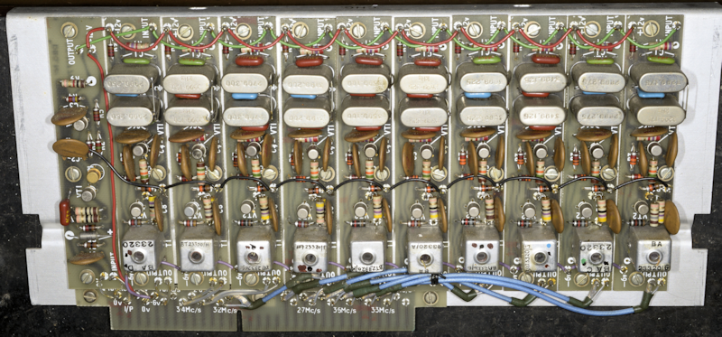 |
Above: Harmonic Generator Module CHG with an inset on the left showing the driver board with the tubular Tantalum capacitor replaced with an aluminium type.
When you work on Racal kit from the 1950s and 1960s you realise just how fortunate we are nowadays in terms of test equipment. Note how often signal measurement asks for a Valve Voltmeter, and in which case the reading is r.m.s. This is because bench oscilloscopes of the day generally did not have enough bandwidth. I have a Racal-Dana 9901A True R.M.S. Voltmeter, but its input is 50-ohms, so in many cases I measure the amplitude on my oscilloscope and divide by 2.2. We take for granted that our general-purpose oscilloscope will have a bandwidth of at least 100MHz, that RF signal generators are all synthesised ... and the advent of small inexpensive spectrum analysers makes it possible to see in real-time what's there and what isn't ... and that's how I realised something wasn't right with the 2.7MHz output from the Harmonic Generator ... the level at the CDDJ was at least 20dB down on all the other outputs. Hence the issue with position zero on all decades.
The manual for the MA350 mentions extension cables and a card extender for diagnostic purposes. To be honest, you don't need the recommended extension cables for the four plug-in modules since there is enough existing cable length to run each module outside the rack by turning the MA350 on its side and reconnecting the module under test on the underside.
The CHG module (Harmonic Generator) can be tested out of the chassis but the loading on the outputs will be off, hence the need for a card-extender. However, this wouldn't be necessary if there was a milled aperture in the rear wall of the main casting which would allow direct access to each of the ten tuneable output transformers (see the image above). The 'Fundamental' for most of what goes on in the MA350 is 100KHz, which is derived from whatever the chosen Frequency Standard is. This is similar to the MA79 where the 14th and 16th harmonics of 100KHz are used to produce signals at 1.4MHz and 1.6MHz. The MA350 takes this even further by using a Pulse Generator as the source of harmonics all the way up to 3.6MHz ... the 36th harmonic of 100KHz. The ten output boards all have a very narrow band-pass filter on the input. Each filter consists of two crystals, which in conjunction with three capacitors is thus tuned to pass only the desired frequency ... in this case 2.7MHz up to 3.6MHz in 100KHz steps.
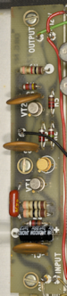
T1 on 2.7MHz board
With the CHG unit on the bench, and with 100KHz supplied from my Adret 7100D, I checked all the RF outputs on my vintage Tektronix 7603. All the waveforms were within spec. in terms of amplitude, and my Racal-Dana 9916 confirmed that in each case the frequency was 'spot-on'. However the waveform of the 2.7MHz output was what I would describe as 'woolly' ... a bit fuzzy ... not crisp and clear. One of the output pins was bent almost horizontal, and straightening it caused it to snap off. A quick check with a multimeter revealed that the secondary of T1, the output transformer, was intermittently open-circuit. As can be seen from the image on the right, the transformer is 'potted'. Fortunately I managed to very carefully peel away the rubber to gain access to the solder spills and flow some solder into each hole. This proved successful. The signal is now clean, the level at 2.7MHz is now on a par with all the others, and I have confidence that the joints are good.
As an aside: Something worth noting here is that the driver stage (actually the harmonic generator itself) employs a Tunnel Diode ... a Philco 1N3562. This is the small gold TO-18 device in the two photographs above. There are five more of these devices in the MA350 ... one in each of the CDDJ modules, and two in the CMJ module. Tunnel Diodes tend to be used in circuits where very fast rise (and or) fall times are required. As such they are ideal for generating harmonics, since mathematically speaking, these incredibly fast edges are rich in harmonics. Where Tunnel Diodes tend to be used at relatively low frequencies, Step-Recovery-Diodes or SRDs were often used to generate harmonics up to several GHz. Tunnel Diodes have been in production since the early 1960s, and although modern technology has seen them superseded, they are still manufactured in small numbers today, and generally NOT in TO-18 format. Expect to pay upwards of £10 for one today.
Although the Harmonic Generator was now working properly, there was still the issue with the peculiar relationship between the 100KHz and 10KHz Decades. To be honest, I had not expected the repair to the 2.7MHz board to change change this ... but at least there was now one less fault to locate. I had already confirmed correct operation of the CRXJ Reference Module. Below are some photographs on what's inside, and what's been replaced.
CRXJ side 1 before.
CRXJ side 1 after.
Above: Clock-wise from bottom-left: Limiter (CRX1), 1MHz Divider (CRX2), 200KHz Divider (CRX3), 100KHz Divider (CRX4), 1MHz Multiplier (CRX6).
The dividers are transistorised incarnations of the valve-based Regenerative Dividers employed in the RA17, RA117 and MA79 etc.
CRXJ side 2 before.
CRXJ side 2 after.
Above: Clock-wise from bottom-left: 200KHz Multiplier (CRX5), Interpolation Oscillator (CRX12), 300KHz Multiplier (CRX10), Hunt Generator (CRX11), Relay A.
Historically, bead-type tantalum capacitors have a history of unreliability. There is an old saying ... 'Never trust a tant, especially a blue one'. When I worked for Racal (1979 - 1992), we used blue 'tants' and the small silver tubular ones. That was many years ago. I have two MA350s in for repair/refurb. As previously mentioned, this one is destined for a client in New Zealand. The other will be going to a UK-client who has much experience with servicing UK manufactured military electronics that is now several decades beyond manufacturer care. I asked him what his policy would be regards the tubular 'tants'. Reinforcing the view that they have a reliable life of only 20 years, he said "replace them". So that is what I have been doing. However, for some reason it isn't possible to get axial aluminium electrolytics small enough to fit where some of the smaller tubular tants came out. However, smaller radial aluminium electrolytics are available, and fortunately they are short enough to fit upright on the boards.
CDDJ before.
CDDJ after.
Above: Anti-clockwise from top-left: Oscillator (CDD1), Mixer (CDD2), Band-Pass Filter (CDD3), Phase Comparator (CDD4), Quadricorrelator (CDD5), Divide by 10 (CDD6). All three CDDJs are identical. The 100Hz and 1KHz CDDJs are in the module adjacent to the CRXJ module. As far as I could ascertain, both of these were working perfectly (at this point), even the 10KHz CDDJ in the CDDJ/CDJ module appeared good.
CDJ before.
CDJ after.
Above: Anti-clockwise from top-left: Oscillator (CDJ1), Mixer (CDD2), Band-Pass Filter (CDD3), Phase Comparator (CDJ4), Quadricorrelator (CDJ5), and Low Pass Filter (CDJ5).
Note how the plate mounting the two connectors is was initially bent. Interestingly, this particular module (CDDJ/CDJ) bore a sticker with the word 'Rejected' written on it. I believe it was dated 1997. This added weight to my theory that this MA350 might have been put together from parts from other MA350s.
It will be noted that on each of the four Phase Comparator boards there is a tubular capacitor that has not been replaced. This is C16 (16uF), a non-polarised capacitor. I suspect it is nothing more than two 32uF tantalum capacitors connected back-to-back inside a common (isolated) metal tube. Not being able to identify a suitable and affordable alternative, I chose to not replace these. On the four Quadricorrelator boards, there are two polyester 100nF capacitors, the sort that we used to say looked like sweeties. The MA350 has more than a few of these, but on the Quadricorrelator, C42 and C43 are too large by about 5mm. Thus in each case, one of the legs is bent right under the capacitor so as to fit the holes in the board. I used to think these 'sweeties' were great, and I loved it when as a teenager, I bought bags of miscellaneous capacitors that contained these. Nowadays I am more likely to rip them out of units as my experience in recent years is that under certain stresses, one or other of the legs very often rips off. In my mind, with one of the legs bent in such an extreme way, the integrity of C42 and C43 was suitably compromised to warrant replacement. Thus, on each of the Quadricorrelator boards, these were replaced with physically smaller capacitors.
We still have the CMJ module to discuss, but up to this point I was more or less happy with the way things were going, even though the 100KHz decade would consistently NOT lock if the 10KHz decade was set to 9, and would occasionally intermittently fail to lock when it (100KHz decade) was set to other settings ... and the condition was showing signs of getting worse. This was interesting, and the manual suggested that this condition might be the result of dirty switch contacts. Which brings us back to the feature where the switch wafers on the end of the decade shafts can be raised up and out of the channel ... for cleaning, perhaps?
I have no less than four spectrum analysers. My Systron Donner covers 10MHz up to 12.4GHz. The spectrum analyser function on my HP8920 is good from below 100KHz up to 1GHz. My TinySA hand-held analyser is good from several KHz right up to just shy of 6GHz ... and can go higher with reduced sensitivity. But when I need a tracking Generator, I turn to my Rigol DSA-815TG which will go down to around 80KHz and up to 1.5GHz.
As previously described, the CDJ module which provides the 100KHz decade works in a slightly different way to the three previous decades. Although the output of the Harmonic Generator (CHG) is still used, instead of going directly to the CDJ Mixer stage, it is diverted to the CMJ module where it is mixed with 7.6MHz to become a range of 100KHz steps between 4.0MHz and 4.9MHz. Using the Rigol Spectrum Analyser to monitor this signal at the input to the CDJ mixer, I noticed that the level varied dramatically over the specified range. It generally varied by about 10dB between 4.0MHz and 4.8MHz, but was at least 20dB down at 4.9MHz. Since the output of the the CMJ is a Band-Pass filter covering 4.0MHz to 4.9MHz, I figured that investigating this filter was probably a good place to start. The manual does not give any details, like pass-band ripple, or 3dB or 6dB points. It even states that adjustment is beyond the scope of a 'normal repair depot' ... hmmm? Sounds a bit like the 40MHz filter in the RA17 ... so shouldn't be problem then.
CMJ side 1.
CMJ side 2.
Above: No Tantalum capacitors to replace in the CMJ.
On Side 1: Anti-clock-wise from bottom left: Pulse Generator (CMJ6), Band-Pass Filter (CMJ11), Amplifier (CMJ10), Buffer Amplifier (CMJ9), Mixer (CMJ8).
On Side 2: Clock-wise from top-left: 200KHz Amplifier (CMJ2), 7.6MHz Filter (CMJ5), Unused space, DC Filter (CMJ3), 4.0MHz - 4.9MHz Band-=Pass Filter (CMJ4).
This filter is indeed very similar to the 40MHz filter in the RA17 in that the 'elements' are all interdependent, so all adjustments need to be small and incremental. It had obviously been tweaked. The excessive pass-band ripple was very obvious and it tended to favour the lower frequencies. It took me a few minutes, but using the Tracking Generator in the Rigol, I eventually managed to minimise the insertion-loss, achieve a pass-band ripple of no more than 2dB and keep the lower and upper limits of 4.0MHz and 4.9MHz within the pass-band. This last part took considerable care since the response rolls off dramatically below 4.0MHz and above 4.9MHz. Satisfied with the filter response, I re-tested the MA350 and found that although the intermittent failure to lock issue was now resolved, thanks to reducing the pass-band ripple in the filter, the 100KHz decade was still not locking as before. However, it now also failed to lock when set to 2. In fact, ALL the other decades were now NOT locking at position 2. This indicated to me that something was not right with the 2.9MHz signal from the Harmonic Generator. This was confirmed when I monitored the input to the mixer in the CDJ module. When the decade was set to 2, there was no signal at 4.2MHz, or at 2.9MHz at the other three CDDJs.
This told me that there was a break in continuity between the CHG module and the bank of switch wafers in the channel above (or below, if the MA350 is the right way up!) the edge connector that the CHG slotted into. The bad news was that the wafer contact was likely one furthest away, i.e. at the bottom of the channel, and with all that coax adorning the switches, it was impossible to even see the edge connector. The good news though was that thanks to the universal joints on the switch shafts, I should be able to 'hinge' the entire wafer assembly out of the channel and see what was amiss.
Failed joint
However it wasn't that easy. Yes, the six Allen screws were easy enough to remove, but getting the assembly to move was another story. When I finally managed to tilt it, it was only by a few degrees. The problem was two-fold. First, there is a hole through which three wires head off to the PSU and a single coax disappears into a tight bundle of similar blue coax. It was necessary to break into the wire harness in the PSU to get some more movement. That worked. However the second issue was a total lack of service loops between the edge connector and the switch wafers. I have no idea how this was assembled!
With the aid of a second pair of hands to hold the wafer assembly out of the way. I was able to identify the offender. It would appear that the coax to pin 5 was completely disconnected ... not broken. I am sure it had barely seen any solder. It wasn't easy, but I was able to push it back into the hole and then solder it properly.
With this repair accomplished, the wafer mechanism was eased back into place (not an easy task, I may add) and the MA350 re-tested. The issue with lack of lock at position 2 on all decades was resolved. Now all that remained was to figure out why the 100KHz decade would not lock when the previous decade was set to 8 or 9. By now I had a good idea what the problem was.
The final circuit in all three CDDJ modules is a Dive-By-10 circuit which provides the Reference for the next Decade Divider. This particular Divider differs from the other dividers which are of the regenerative type. This divide-by-10 is much more sophisticated and clever in that it uses a Tunnel Diode Oscillator where T8 is tuned to roughly one fifth of the 3MHz - 4MHz output from the VCO (CDD1). It is then fine-tuned by the output of the Phase Comparator (CDD4). This way the Tunnel Diode Oscillator tracks the VCO, but at one fifth the frequency. Transistor VT19 amplifies the output of the Tunnel Diode Oscillator, while T9 is tuned to respond to frequencies between 600KHz and 800KHz. T10 is tuned to respond to frequencies between 300KHz and 400KHz. The non-linear nature of diodes MR14-MR17 produces the sum and difference of these signals. The mixer is self-inducing since any impulse in the secondary of T10 will result in regenerative feedback from VT20 via C51, which maintains the mixing process. VT21 is the final stage of amplification. I trust this makes sense.
While using the Rigol Spectrum Analyser to observe the output of this divider (output of CDDJ3) while the 10KHz decade was set to 0 through to 9, I noticed that while the output level was fairly constant for settings of 0 to 7, it dropped off about 6dB on 8 and almost 20dB when set to 9. All that was required was a very minor tweak, about one quarter turn of T10 to bring the levels up at the high end of the scale. In short, T10 was tuned a wee bit low. With T10 re-tuned, I re-tested the MA350 ... BINGO! The MA350B now locks on every setting. No, I can't say that, I don't have time to do that! All four decades now flawlessly lock on every setting, and the output is a lovely rock-steady Sine Wave.
MA350B Ser. No.359 - Fully functional.
Above: The fully functional MA350B, complete with correct Red Out Of Lock lens. When re-fitting the top and bottom covers, I discovered that this MA350 must have been dropped at some point. The bottom right corner of the front panel isn't true. It has been bent slightly, then imperfectly straightened. Attempting to correct this aberration would only further damage the paint in that area. The bottom cover had clearly received a hefty blow, such that it was no longer flat. The thin aluminium had stretched, and no amount of bending was ever going to make any difference ... unless you know a panel beater! This was the reason why the connector panel on the CDJ module was bent.
The MA350B controlling an RA1218.
Above: Just for fun, I connected the MA350B up to an RA1218. Here, the MA350B is supplying three inputs ... the 2nd VFO, the 3rd VFO (1.7MHz) and the 1MHz signal. It was very reassuring to see that the Nixie display mirrored the MA350B settings.
Finally: One feature of the MA350 that has not been discussed is the Interpolation Oscillator. The control for this is the one with the round knob and the graduated scale behind the crescent window. Strictly speaking, this control is ONLY relevant when the MA350 is providing the 2nd VFO for an RA117. Its purpose is for honing the output frequency of the MA350 to the precise frequency of a received signal. The Interpolation Oscillator can therefore be used to assist in setting the 1KHz, and 100Hz decades in turn. It is set up like this ... These two decades are each set in turn so that the red pane is visible in the window. This action causes the scale for the Interpolation Oscillator to illuminate. The 100KHz and 10KHz decades are set for a frequency close to the desired frequency and the receiver BFO is switched on. Then starting with the 1KHz decade, the Interpolation Oscillator is tuned until a zero-beat is heard on the receiver. The reading on the scale is noted and the 1KHz decade is set to the most significant digit. i.e. if the reading is 38, the decade should be set to 3. The operator then moves on to the 100Hz decade and repeats the process, setting the 100Hz decade to the appropriate setting. Should it be necessary, the final switch, to the left of the Interpolation Oscillator control, can be used to further fine tune the receiver to within 1Hz, in which case that two-position switch should be left with the red pane visible.
Thus, the Interpolation Oscillator provides three levels of variation ... 10KHz, 1KHz and 100Hz.
N.B. ... The MA350 will NOT lock unless ALL the decades are set to a valid integer i.e. 0 to 9.