Fully Loaded MA79G
33 minute read
This post is part of the series 'MA79 Drive Units':
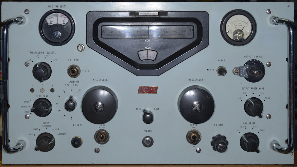
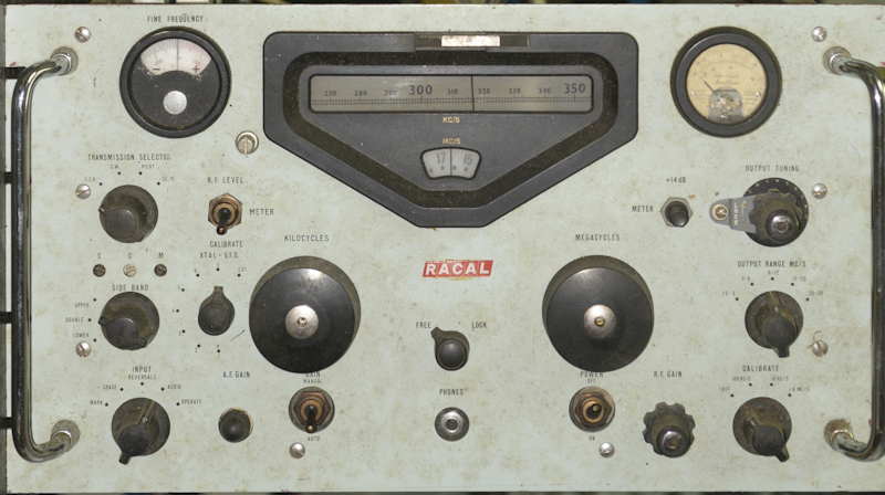 I think this is the fifth MA79 that I have restored to working order. The difference with this one is that it has been assembled from parts salvaged from two MA79s which had been stripped for parts. The chassis was originally that of an MA79A-1 with serial number N139, fitted with an LA255 and had also been modified to include three additional HT fuses. This MA79 had not been treated well, so I had been using it for spares. The other 'donor' had been in such poor condition that I had gone as far as stripping it completely. The photograph above is the front panel taken from the second MA79. The panel from MA79 N139 had a very nasty gouge taken out just below the meter-function toggle-switch.
I had been asked by a client if I could provide him with a fully working MA79 for a museum exhibit that he was planning. I had a look in my 'store' and informed him that I had enough parts to put together an MA79G if he could source either a Lavoie or a Knights crystal oven for the 1MHz crystal. And that he did. And not only did he present me with a lovely Knights oven, he had also managed to procure a brand new shiny, never issued, Calibrator assembly (see below), two Ernest Turner meters, one for an MA79 and one for an RA17, a pair of shiny new handles, a spare 1MHz crystal (NOS) and a 1.7MHz crystal (NOS) for an RA117. Sadly, the MA79 meter was u/s due to an open-circuit movement.
I could just have easily put together and MA79H, but that would have necessitated the inclusion of an accompanying MA350 as part of the exhibit, and over-complicate things. I hit on the idea that since I was 'making' an MA79G, I could make it 'fully loaded'. I would give it the option for accepting an external 1.4MHz modulated signal as well as routing the internally generated 1.4MHz modulator output to the rear panel. I would also fit an LA255 Tone Keyer (sometimes known as a Tone to DC Convertor) ... and since I was doing that, I might as well fit the sub-chassis that carries the additional three HT fuses.
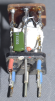
Whereas, there are those who look upon the humble calibrator in the RA17 as an enigma ... the LA255 certainly trumps that. This morning whilst in my Racal 'store', I found this brand new LA255 ... never issued, complete with carefully prepared wire ends etc. On one end it is described as 'Tone to DC Convertor type LA255', whilst on one side there is a plate giving the nsn as 5820-99-580-1976 and describing it as a 'Keyer Tone' ... or a Tone Keyer, once translated from MOD-speak. I can't help thinking that this little box facilitated a form of VOX by generating a DC voltage from the modulation drive signal and thus in some way activating Relay RLB ... but it doesn't ... or at least not directly, or any way that I can see.
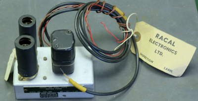
Left: I now had a plan of action. The MA79 that I picked to resurrect was missing the audio input transformer and associated wire harness, but I had one taken from a scrapper (in the poly bag on the left along with an LA255 and additional fuses assy.). Note the 2-pin mains connector in the photograph ... hmmm? The MA79 in the background is an MA79H which is next in-line and is destined for a client in New Zealand.
But first, the current subject needs to be stripped down ... KHz and MHz VFO modules removed from the chassis ... all valves tested and chassis cleaned before I can start the refurbishment process. I used to find dismantling such a complex piece of equipment daunting, but over the years I have learned to treat each module as a separate testable entity ... and it simply becomes a process of strip down, refurbish and re-test, then move on to the next module.
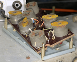
Above: Note the yellow arrow. This is L18 on the Modulator Assy. In this case, it is not a full-height can, confirming my suspicion that MA79 N139 started out as an MA79A which was intended to accept an externally-generated modulation signal, and thus did not use the internal modulator. Yet it did have the rear-panel potentiometer for adjusting the level of modulation. Very odd. I simply replaced the short can L18 with a full-height one from a scrap chassis.
Also worth noting here: The windings in the the short L18 and long L18 are identical. The only reason for the difference in height is simply to accommodate the additional capacitor (C64, 3900pF) in series with C66, 150pF. Together, as well as forming a tuned circuit with L18 primary, they also provide a potential divider for the optional 1.4MHz output. As an experiment, I managed to modify the short L18 to take the extra capacitor ... and it appears to work. See right.
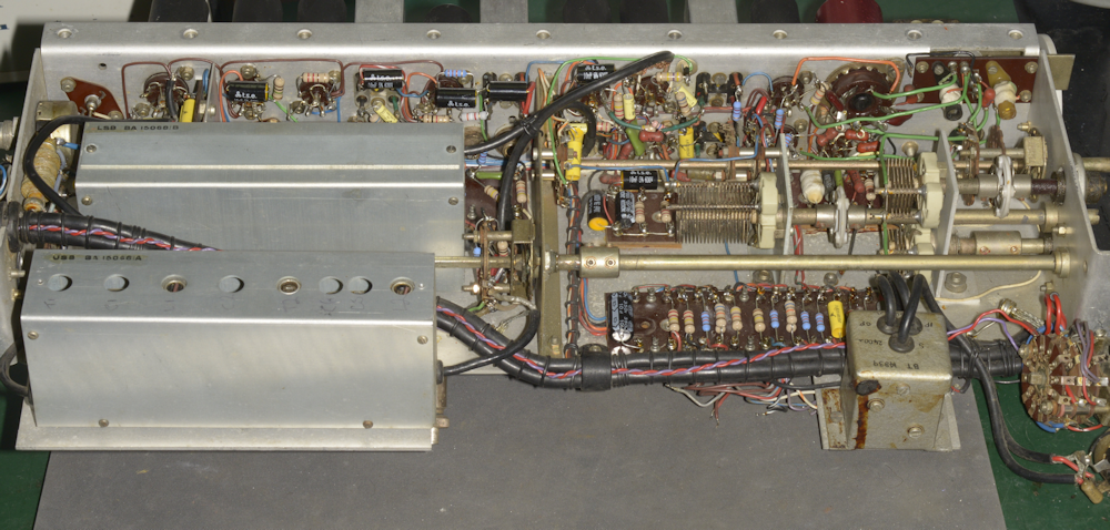
The MA79 is often likened to an RA117 operating in reverse. With much of the metalwork being common, this is actually a reasonable description. The operating principle is very similar; the 'numbers' that matter, the clever arithmetic, are the same. Although in reality the MA79 is far more complex. The photograph above demonstrates this. Here the basic 1st VFO casting is used as the basis for the MHz VFO and PA module. Thus in terms of circuitry, what is the first module in the RA117 is the final module in the MA79.
Apart from the expected smattering of out-of-spec resistors which had aged high over the last 60 years, I found no evidence that might allude to something catastrophic having occurred in the past.
Unlike the alignment procedure for the RA17, there are no alignment details in the MA79 manual relating to the tuned circuits in the PA. In the past I have tried to apply the RA17 (MK1 and MK2) procedure to the MA79 PA, but with little success. In fact, I had no need to make any adjustments when I tested the refurbished module on my bespoke test-jig (on right).
My TinySA Ultra proves to be one of my best purchases when it comes to aligning the MHz VFO. I simply sit it next to the test-jig and extend the telescopic whip ... much easier than the procedure in the manual ... and since there is no actual contact, there is no risk of frequency pulling.
Having said that the MA79 is 'like' an RA117 in reverse; The KHz VFO however is completely different. The photograph below illustrates this. The base casting bears more resemblance to that in the RA17 whilst the circuitry there-in is unique to the MA79.
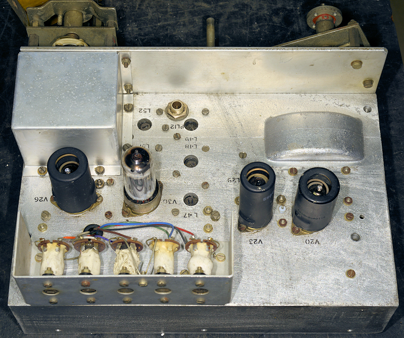
There are no less than three ovens in the MA79G. Two of which are simply crystal ovens ... one for the 1MHz crystal and a dual-oven for the 5MHz and 5.1MHz crystals. The KHz VFO assembly embodies the third oven (technically Oven 1, according to the schematic). In the photograph above, this is the box on top of the base casting. Like the oven for the 1MHz crystal, this oven runs from a nominal 110V a.c. supply. I have often wondered why 110V was chosen. Perhaps the sheer size of the box on the KHz VFO would be to difficult to heat from a 6.3V source. Also, with three ovens involved, that would dramatically increase the load on the mains transformer. The relay on the rear of the film-strip carrier delivers the 110V to the heating element.
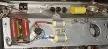
Left: The 'oven' on the KHz VFO in the MA79 is similar to that in the RA218 ISB adapter. The heating element is wound around the inner box, which houses the critical components for the VFO and up to six optional crystals. The thermostat is of the mercury-added type. This is the long black device in the top left corner of the photograph.
The KHz VFO is actually two switchable oscillators ... on offer are a highly stable L-C VFO and a crystal oscillator. There is also the option for an external source such as from an MA350
As with the MHz VFO, the first thing I did, after verifying that the heater element was intact, was give it a good clean. It was during this process that I found the spring for the brake pad for the MHz VFO mechanism was missing ... see below.
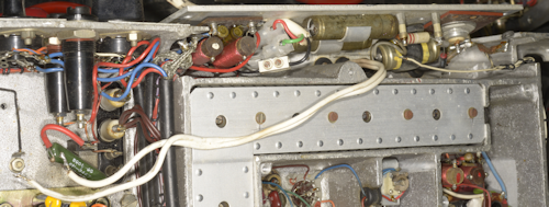
Unlike the RA17 or RA117, the 'power supply' for the MA79 appears to be 'distributed'. By that, I mean that elements of the HT and -ve supply are not confined to the area around the mains transformer. The photograph on the right is a case in point. This is the connector supplying the HT and heater supply to the KHz VFO. The wave-wound inductor is L10 which is in series with the mercury thermostat and the vitreous-enamelled wire-wound resistor is R161 which has nothing to do with the KHz VFO but is part of the +200V line.
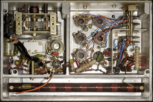
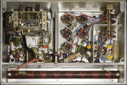
The circuitry under the KHz-VFO base chassis is relatively easy to work on. However, you will note the difference in the following two photographs. I'm not sure why, but R44 (1K) and C40 (10nF) appeared to be missing, and the wiring associated with PL14 did not match the schematic. This may have been peculiar to the MA79A. In the end I chose to fit R44 and C40 and re-wire PL14 as per the diagram.
Having replaced the at-risk Rs & Cs in the KHz VFO, I powered it up. I wasn't anticipating any problems, and at first sight all looked good. With an appropriate crystal inserted, the crystal oscillator delivered a healthy sine-wave as did the VFO when selected. However, the frequency of the latter was significantly 'out'. Such was the error that it was not a simple case of adjusting L14 or C46. Initially I thought that L14 was damaged. Then I noticed that the meshing of the vanes of C47 appeared wrong ... too much or too little meshing depending on which end of the film scale the cursor was at. It was then that I realised that both the Allen grub-screws in the milled insulated tuning shaft were loose. So loose in fact that it was possible to move the rotor vanes whilst preventing the outer shaft from turning. Rectifying the situation was simply a case of following the procedure in the manual for replacing C47.
Moving on to the Calibrator now ...
If this were an RA17, we'd be looking at a somewhat simple power supply and a pair of RF pentodes pressed into action as audio amplifiers. Instead, since this is an MA79, the bulk of this space is occupied by a seemingly confusing conglomeration of valves. Welcome to the Calibrator!
Like the rest of the MA79, when you break it down, the Calibrator is less daunting than you might expect. As in the RA17, calibration at 100KHz intervals is standard. Then as in RA17s (known rather incongruously as the KL/GRR3011A) sold to The Netherlands, calibration is also offered at 10KHz intervals. Finally, there is also a 1.6MHz calibration position which is employed when adjusting the Fine Frequency control and acts on the 5.1MHz (10.2MHz) oscillator.
But the Calibrator is more than just a calibrator. In the MA79 the Calibrator is cunningly used to generate the 1.4MHz signal which is fed to the Modulator, and thus becomes a crucial part in the R.F. generating chain. Unlike in the RA17 etc. where the Calibrator is only switched on when required, the Calibrator in the MA79 is running all the time. More precisely, while the 100KHz divider runs 100% of the time, the 10KHz and 1.6MHz circuits only run when calibration is selected.
The 100KHz output is applied to V31 (EF91) where the 14th and 16th harmonics are extracted in L53 and L54 respectively. The output from L54 is used for performing the 1.6MHz calibration whilst the 1.4MHz from L53 is fed to the Modulator, V9 (EF91). I thinks its very clever ... and a spectrum analyser is a must when tuning L53 and L54.
As with the RA17, calibration is an aural thing, hence the headphones jack on the front panel, which might appear a bit odd on a transmitter, but is a whole lot easier than using the front panel meter (selected via the Meter Selection Switch). The Calibrator effectively has its own radio receiver comprising V33 (6AS6) and V32 (EF91) to make aural calibration possible ... also rather clever.
At this point I did consider tackling the Power Supply, but thought it wiser to leave that to the end as the task would involve careful re-wiring to incorporate the three additional HT fuses. So ... on to the Modulator assembly!
And its at this point of writing this article that I realise that I hadn't taken detailed pre-refurbishment photographs of the Modulator. So you will have to take my word regarding the following photograph.
The photograph above shows the Modulator assembly during re-work. As you can see, a previous owner had replaced the 12-pin Belling-Lee connector with an 8-pin Octal socket. This is the second time I have encountered the early 'discrete' style Sideband filters. Rather worryingly the USB filter is missing the cover over the holes, and the enclosed component designations have been scratched onto the body. I was able to confirm that the passband of both filters were the same, albeit one a mirror-image of the other, which did put my mind at ease. The LSB filter is temporarily removed to allow better access to the wafers of Switch SE which I have replaced with 4-way wafers so as to facilitate an external 1.4MHz input. There is a note on Fig. 6 in the manual which states that the EXT position is not available on the MA79A.
Whilst I was more or less happy with the sideband filters, the same could not be said for the 2MHz-3MHz Filter. This is the same filter found in the RA117. Unlike in the RA117 where this filter is mounted on the main chassis; in the MA79 it is attached to the rear of the Modulator Assembly ... and in order to remove the LSB filter, it is first necessary to completely dismantle the 2MHz-3MHz filter in order to gain access to two of the four retaining screws, which doesn't sound like a good mechanical arrangement to me.
Three out of the seven coil-formers had suffered from age-related degradation. Historically, anywhere Racal have used this style of former, such as in the RA37, RA137 and RA237, today they will without doubt be brittle to the point of disintegrating. Recently I made a point of stocking up on new formers, but I wasn't expecting to have to replace so many. As it was, I was able to reassemble the filter and re-tune (where necessary) to the point that it met the spec.
The photograph above shows the Modulator assembly after full refurbishment. I added a third wafer to Switch SC to accommodate the twisted red and violet pair of wires which is present on MA79s which feature the LA255. I still have to test the modulator, but not until I have fitted the three additional HT fuses. It is now time to tackle the power supply. Starting at the beginning ...
As noted in an earlier photograph, the method of connecting this MA79 to the UK mains supply had been direct (no Plessey connector) and via and ancient 2-pin plug. If memory serves, these tended to be rated at a mere 2A. The flat-twin white wire was across the transformer primary and connected to two anonymous 4mm binding posts on the original rear panel assembly ... definitely not safe!
While still on the subject of the Power Supply. More PSU-related components can be found behind the front panel, between the ALC switch and the Mains switch. These include R196, 150R and C198, 100uF which relate to the -ve 25V line. And don't forget R161, 1K, 7W adjacent to the KHz VFO which is the dropper for the +200V line.
Finally we have C197, 32uF, the smoothing capacitor for the +200V line, which is nowhere near R161, but is adjacent to the tag-strip to which the Modulator assembly is wired. I have to wonder why so many of the PSU circuitry is seemingly distributed around the chassis haphazardly.
Admittedly, and inevitably, this all makes diagnosing faults that little bit more time consuming. Likely a necessity on account of the Calibrator taking up so much space. But this practice of distribution isn't limited to the physical. Take a look at the circuit diagrams ... in particular to Fig. 4 which Racal refer to as Ancillary Circuits. Its really the Power Supply, and I get the fact that all the module filter chokes etc. are shown together, but why have they not identified which module/circuit they each serve? Then note the inclusion of R183 at the bottom of the page. Would it not be more logical to show this resistor on Fig. 3? And surely D8, across RLA is shown the wrong way round?
Moving on ... time to put it all back together, re-wire the HT to accommodate the three additional fuses, and fit the LA255 ... but first, remember to change the two resistors on the end of the 30MHz LP filter on the output of the Harmonic Generator ... the KHz VFO module obscures the retaining screws.
And here I must make a confession. My re-draw of Fig. 4, to include the three additional HT fuses was originally totally wrong. I can't remember what I based that on, but I have now corrected the errors having carefully traced the wiring in the MA79H that is awaiting refurbishment. A link to the correct diagram, and others is at the end of this article.
The LA255 is mounted on its side on the rear panel. The sub-chassis that carries the three additional fuses sits on top of the rear panel, sharing three of the screws securing the LA255. The terminal block with the brown and violet wires appears to be a feature when the LA255 is fitted. The violet wire is the -ve 25V line and the brown wire is connected to the junction of RLB, R56 and R55 ... so looks like a connection for a CW key.
Here's a curious observation. All the screws on the MA79 are British BA threads, with the exception of the two screws securing the safety cover at the rear of the three additional fuses, which are 4-40 UNC ... why?
Here's a couple of photographs of the MA79, re-built, but still awaiting the front-panel. I still have to test the Modulator and refurbish the compartments under the main chassis. Testing of the Modulator assembly was deliberately left until now since it is easier to do as part of the whole MA79. This obviously assumes that the as yet un-refurbished parts are functional. These are the 1MHz Oscillator, Harmonic Generator, Harmonic Mixer and 2nd Mixer ... all of which I have confidence in.
The Knights oven in the centre of the main chassis was warming up, as was the dual oven on the Modulator assembly, and after several minutes I heard the reassuring 'thunk' of RLA switching off, indicating that the thermostat in Oven 1 was doing its thing. All was indeed looking good.
The best way to test the Modulator assembly is to follow the procedure in Section 2 of the manual ... probably start at chapter 6 entitled F.S.K. and Fine Frequency Calibration. This tests and verifies two crystal oscillators (10MHz and 10.2MHz). Although a tad laborious in places, everything aligned nicely. I skipped chapters 7 and 8 since I had aligned the MHz and KHz VFOs earlier, although I did verify that all three Calibrator settings were functional.
The method in the manual for aligning the various mixers in the Modulator assembly is typical of a time when spectrum analysers were a luxury ... not commonly found on a technicians bench. Again, my little TinySA Ultra made short work of assisting in identifying and discerning wanted and un-wanted mixing products throughout the chain of three mixers (see above diagram). For measuring the output power of the MA79G, I use a Racal-Dana 9100 Absorption Wattmeter with my Rigol DSA915TG connected to the monitor output which is -23dB on the input.
I was delighted to see that this MA79 was happy to deliver more than enough CW signal than that specified over the range of 1.5MHz to 30MHz. I verified that the Pilot carrier could be varied of a range of -6dB to -26dB and I was beginning to think that this might be the best MA79 that I had encountered ... until I realised that something was not right with the DSB (AM) modulation.
In the MA79, the modulation signal is buffered by V6B, configured as a cathode-follower. This signal is applied to the centre-tap of the L18B, where it modulates the signal developed across L18. I was monitoring the output of the MA79G on a spectrum analyser and was barely managing to get more than 30% amplitude modulation. The gain of a cathode-follower is generally slightly less than 1. On this occasion I was seeing close to 20dB of attenuation. Something was clearly amiss with the cathode-follower. The valve, a 12AT7 was checked on my VCM163 and confirmed to be well within spec. so the problem had to be with the wiring, or a failed component. What I did discover was that the voltages on the grid and cathode of V6B were completely wrong. The cause of this was not what I expected.
The problem was definitely linked to the small tag-board on which I had replaced everything except the choke, and that checked out OK. So what else could be wrong. I then remembered that having stripped down two MA79s, I had a spare cathode-follower tag-board. I removed each of them from their little sub-chassis, and there in front of me was the cause of much head scratching. Note the black wire on the reverse side. This is a classic manufacturing error. When the board had been assembled, the black wire had been soldered in place. Then before the rest of the wires and components were added, the board was inadvertently turned through 180 degrees. Very likely a distraction caused by a tea-break. Remember, this was originally an MA79A where the Modulator was not used ... thus the wiring error was never discovered until now. Easily rectified by changing the placement of the black wire.
So that resolved the modulation level issue ... but moving, on I found a serious issue associated with the output power when LSB or USB was selected. I was seeing a drop in excess of 20dB when either sideband was selected. Output power remained very healthy when DSB was selected. Remember, the sideband filters in this MA79 were the early discrete component type. However I did have a seriously stripped down modulator assembly complete with two filters of the later encapsulated type. Would these both be good? Comparing the filters, like for like, although the shape-factor was more or less identical, for some reason the older filters were presenting at least 20dB more attenuation than the encapsulated type. I substituted the encapsulated USB filter for the discrete filter and found that the power level for that sideband was restored. Doing the same with the other filter restored that sideband power also. What is puzzling is that the shape and pass-band of the discrete filters is very similar to that of the encapsulated ones ... they just incur a whopping extra 20dB of loss. Obviously, I decided that the best solution here was to swap out the discrete ones and fit the newer encapsulated ones. But to do that, on account of the mounting method of the older filters, the entire Modulator Assembly would need to be detached.
The issue here is one of interference. Whereas the older filters mount directly onto the sub-assembly, the newer ones are supported on individual 6BA pillars, which ultimately means that if one of them should fail, and I have encountered one failed encapsulated filter, they are relatively simple to replace. Replacing a discrete filter is another matter ... especially if an LA255 is fitted!
To gain access to two of the screws securing the LSB filter, the 2MHz to 3MHz filter needs to be literally dismantled. The lid needs to come off then the filter board needs to be lifted off its supports ... just to get at two screws. However before the lid of the filter can be eased off, the LA255, and anything else attached to the inside of the MA79 rear panel needs to be removed first ... tedious, but not necessarily difficult.
Having done this, I removed the old filters, fitted the eight 6BA pillars and fitted and wired in the new encapsulated filters. Since I knew these worked I continued to re-fit the LA255 etc. and powered up the MA79G ... NOTHING! Or more accurately, no RF output, on any mode. Off came the LA255 etc, off came the filter, and sure enough, there's the fault. The inner of the output coax had snapped off. Easily fixed, but still no RF output. This time I discovered that the much thinner input coax inner had snapped off. This time though, I removed the filter completely and tested it using the tracking generator on my Rigol analyser. This test is not ideal since the Rigol is a 50-ohms device and the filter impedance is more like a few thousand ohms. But it does give a go-no-go result. In this case, even with both coaxes securely repaired, nothing was getting through the filter.
 A completely open-circuit Hunts 10nF capacitor! What are the odds of both coaxes and the input capacitor failing simultaneously? Very low, I'd say. The output coax likely failed the first time I eased the lid off the filter. Not sure about the input coax, other than lifting the board likely contributed to the failure. But the chances of the capacitor also failing ... hmmm?
With a new capacitor fitted, it was like a switch had been flipped ... and the MA79G was again singing very nicely.
Now back to the refurbishment process, and the three remaining under-chassis compartments.
Left: Everything in this photograph looks just like what you'd expect in an RA17, except for a couple of differences. The obvious difference is the presence of the Octal connector for the temperature-controlled oven. The other difference is that despite the crystal oscillator circuit being a Colpitts, as in the RA17, the circuit in the MA79 is somewhat different. Also note that the trimmer capacitor is almost fully meshed.
The circuitry in the Harmonic Mixer compartment is identical to that in the RA17.
Left: I should have pointed out earlier that the original wiring in the Oscillator compartment had been configured for a Lavoie oven. Since I fitted a Knights oven, changes were required; hence the pink wires. I also added a 15pF silvered mica capacitor across the trimmer capacitor so that it is no longer fully meshed when adjusted for exactly 1MHz. Initially I thought that two of the ceramic 1nF capacitors in the Harmonic Mixer compartment had been changed, but it turns out that the two green silvered mica capacitors at the bottom are still 1nF.
Right: Looking just like the 2nd Mixer in the RA17, this is effectively the second-last mixer in the MA79, although the circuit diagram calls it the 2nd Mixer. This circuit effectively operates in reverse to its RA17 counterpart. It mixes the 2-3MHz signal from the modulator assy. with the 37.5MHz from the Harmonic Mixer to produce a signal between 39.5MHz and 40.5MHz.
Right: Job done! No issues encountered with this circuit. All compartments and modules fully refurbished ... all 'at risk' Rs and Cs replaced and an MA79G that I have full confidence in. All that is left is to make up a suitable Mains cord with a Plessey connector and look out a mating connector for the 12-way Belling-Lee plug at the rear.
Here are some screen grabs from the Spectrum analyser of the MA79G operating ...
Having not made any adjustment to the 40MHz Bandpass filter, I used the tracking generator on the Rigol to demonstrate the shape and integrity of the filter ... absolutely spot-on! So I just left it. When something is working well, best leave it alone.
Finally two end-result photographs of the MA79G ...
And as promised ... links to the updated and corrected diagrams ... Technical Manual ... Includes section on the MA284 and a circuit diagram for the LA255.
Block diagram for MA79G (Fig. 1)
Block diagram for MA79H (Fig. A-1)
MA79G Calibration and Output Stages, (Fig. 3) ... updated May 2025
MA79H Calibration and Output Stages, (Fig. A-5) ... updated May 2025
MA79G Modulation and IF Stages, (Fig. 2) ... Updated May 2025
MA79H Modulation and IF Stages, (Fig. A-4) ... Updated May 2025 ... Figures 2 and A-4 have been modified to reflect Change No. 2, Issue 6, June 1971. Included in the manual. Note the reference to a -35V line. I have kept to this reference when making changes to the circuit diagrams. This may be a genuine 'typo', or it may be a 'nod' to the fact that the -25V line is nominal and is actually closer to -35V at the best of times.
MA79 Ancilliary Circuits, (Fig. 4) ... updated March 2025
MA79 Ancilliary Circuits, (Fig. 4), modified ... Updated March 2025 ... Modified to reflect units where three additional HT fuses have been fitted, notably when the LA255 is fitted.
Next post in the series: Transmitter Drive Unit Type MA79H
- The MA79 Transmitter Drive Unit
- Poor Man's MA350
- Fully Loaded MA79G
- Transmitter Drive Unit Type MA79H
March 2025
I had been asked by a client if I could provide him with a fully working MA79 for a museum exhibit that he was planning. I had a look in my 'store' and informed him that I had enough parts to put together an MA79G if he could source either a Lavoie or a Knights crystal oven for the 1MHz crystal. And that he did. And not only did he present me with a lovely Knights oven, he had also managed to procure a brand new shiny, never issued, Calibrator assembly (see below), two Ernest Turner meters, one for an MA79 and one for an RA17, a pair of shiny new handles, a spare 1MHz crystal (NOS) and a 1.7MHz crystal (NOS) for an RA117. Sadly, the MA79 meter was u/s due to an open-circuit movement.
Above: The 'never issued' MA79 Calibrator Assembly, which would subsequently be completely refurbished despite its mint condition.
I could just have easily put together and MA79H, but that would have necessitated the inclusion of an accompanying MA350 as part of the exhibit, and over-complicate things. I hit on the idea that since I was 'making' an MA79G, I could make it 'fully loaded'. I would give it the option for accepting an external 1.4MHz modulated signal as well as routing the internally generated 1.4MHz modulator output to the rear panel. I would also fit an LA255 Tone Keyer (sometimes known as a Tone to DC Convertor) ... and since I was doing that, I might as well fit the sub-chassis that carries the additional three HT fuses.
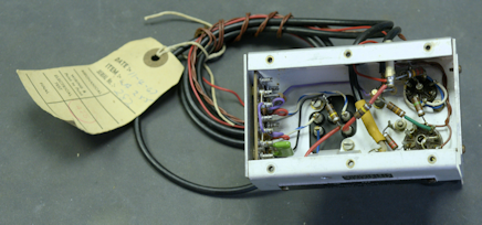
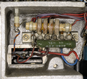
Brand New LA255
LA255 (Underside)
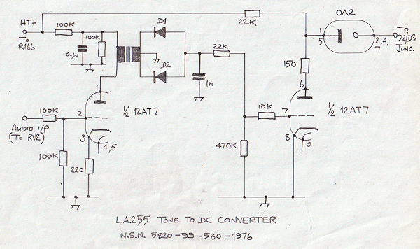
LA255 Schematic and connection details.
Whereas, there are those who look upon the humble calibrator in the RA17 as an enigma ... the LA255 certainly trumps that. This morning whilst in my Racal 'store', I found this brand new LA255 ... never issued, complete with carefully prepared wire ends etc. On one end it is described as 'Tone to DC Convertor type LA255', whilst on one side there is a plate giving the nsn as 5820-99-580-1976 and describing it as a 'Keyer Tone' ... or a Tone Keyer, once translated from MOD-speak. I can't help thinking that this little box facilitated a form of VOX by generating a DC voltage from the modulation drive signal and thus in some way activating Relay RLB ... but it doesn't ... or at least not directly, or any way that I can see.
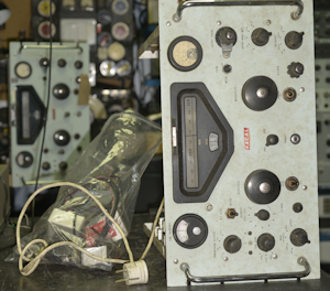
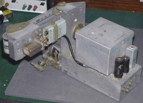
Left: I now had a plan of action. The MA79 that I picked to resurrect was missing the audio input transformer and associated wire harness, but I had one taken from a scrapper (in the poly bag on the left along with an LA255 and additional fuses assy.). Note the 2-pin mains connector in the photograph ... hmmm? The MA79 in the background is an MA79H which is next in-line and is destined for a client in New Zealand.
But first, the current subject needs to be stripped down ... KHz and MHz VFO modules removed from the chassis ... all valves tested and chassis cleaned before I can start the refurbishment process. I used to find dismantling such a complex piece of equipment daunting, but over the years I have learned to treat each module as a separate testable entity ... and it simply becomes a process of strip down, refurbish and re-test, then move on to the next module.
MA79, stripped and ready for cleaning.
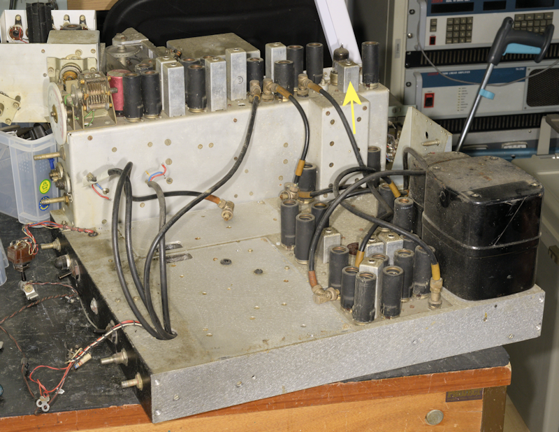
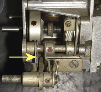
Above: Note the yellow arrow. This is L18 on the Modulator Assy. In this case, it is not a full-height can, confirming my suspicion that MA79 N139 started out as an MA79A which was intended to accept an externally-generated modulation signal, and thus did not use the internal modulator. Yet it did have the rear-panel potentiometer for adjusting the level of modulation. Very odd. I simply replaced the short can L18 with a full-height one from a scrap chassis.
Also worth noting here: The windings in the the short L18 and long L18 are identical. The only reason for the difference in height is simply to accommodate the additional capacitor (C64, 3900pF) in series with C66, 150pF. Together, as well as forming a tuned circuit with L18 primary, they also provide a potential divider for the optional 1.4MHz output. As an experiment, I managed to modify the short L18 to take the extra capacitor ... and it appears to work. See right.
The MHz VFO/PA module scrubbed up well.
The MA79 is often likened to an RA117 operating in reverse. With much of the metalwork being common, this is actually a reasonable description. The operating principle is very similar; the 'numbers' that matter, the clever arithmetic, are the same. Although in reality the MA79 is far more complex. The photograph above demonstrates this. Here the basic 1st VFO casting is used as the basis for the MHz VFO and PA module. Thus in terms of circuitry, what is the first module in the RA117 is the final module in the MA79.
Before refurbishment
After refurbishment
Apart from the expected smattering of out-of-spec resistors which had aged high over the last 60 years, I found no evidence that might allude to something catastrophic having occurred in the past.
Unlike the alignment procedure for the RA17, there are no alignment details in the MA79 manual relating to the tuned circuits in the PA. In the past I have tried to apply the RA17 (MK1 and MK2) procedure to the MA79 PA, but with little success. In fact, I had no need to make any adjustments when I tested the refurbished module on my bespoke test-jig (on right).
My TinySA Ultra proves to be one of my best purchases when it comes to aligning the MHz VFO. I simply sit it next to the test-jig and extend the telescopic whip ... much easier than the procedure in the manual ... and since there is no actual contact, there is no risk of frequency pulling.
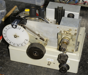
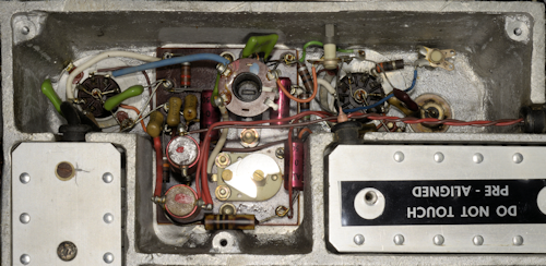
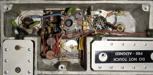
Having said that the MA79 is 'like' an RA117 in reverse; The KHz VFO however is completely different. The photograph below illustrates this. The base casting bears more resemblance to that in the RA17 whilst the circuitry there-in is unique to the MA79.
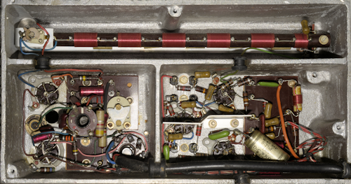
Example of a KHz VFO from an MA79.
There are no less than three ovens in the MA79G. Two of which are simply crystal ovens ... one for the 1MHz crystal and a dual-oven for the 5MHz and 5.1MHz crystals. The KHz VFO assembly embodies the third oven (technically Oven 1, according to the schematic). In the photograph above, this is the box on top of the base casting. Like the oven for the 1MHz crystal, this oven runs from a nominal 110V a.c. supply. I have often wondered why 110V was chosen. Perhaps the sheer size of the box on the KHz VFO would be to difficult to heat from a 6.3V source. Also, with three ovens involved, that would dramatically increase the load on the mains transformer. The relay on the rear of the film-strip carrier delivers the 110V to the heating element.
Left: The 'oven' on the KHz VFO in the MA79 is similar to that in the RA218 ISB adapter. The heating element is wound around the inner box, which houses the critical components for the VFO and up to six optional crystals. The thermostat is of the mercury-added type. This is the long black device in the top left corner of the photograph.
The KHz VFO is actually two switchable oscillators ... on offer are a highly stable L-C VFO and a crystal oscillator. There is also the option for an external source such as from an MA350
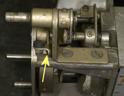
As with the MHz VFO, the first thing I did, after verifying that the heater element was intact, was give it a good clean. It was during this process that I found the spring for the brake pad for the MHz VFO mechanism was missing ... see below.
Floppy brake-pad
New spring fitted
Unlike the RA17 or RA117, the 'power supply' for the MA79 appears to be 'distributed'. By that, I mean that elements of the HT and -ve supply are not confined to the area around the mains transformer. The photograph on the right is a case in point. This is the connector supplying the HT and heater supply to the KHz VFO. The wave-wound inductor is L10 which is in series with the mercury thermostat and the vitreous-enamelled wire-wound resistor is R161 which has nothing to do with the KHz VFO but is part of the +200V line.
The circuitry under the KHz-VFO base chassis is relatively easy to work on. However, you will note the difference in the following two photographs. I'm not sure why, but R44 (1K) and C40 (10nF) appeared to be missing, and the wiring associated with PL14 did not match the schematic. This may have been peculiar to the MA79A. In the end I chose to fit R44 and C40 and re-wire PL14 as per the diagram.
KHz VFO before refurbishment
R44 and C40 fitted and PL14 re-wired
Having replaced the at-risk Rs & Cs in the KHz VFO, I powered it up. I wasn't anticipating any problems, and at first sight all looked good. With an appropriate crystal inserted, the crystal oscillator delivered a healthy sine-wave as did the VFO when selected. However, the frequency of the latter was significantly 'out'. Such was the error that it was not a simple case of adjusting L14 or C46. Initially I thought that L14 was damaged. Then I noticed that the meshing of the vanes of C47 appeared wrong ... too much or too little meshing depending on which end of the film scale the cursor was at. It was then that I realised that both the Allen grub-screws in the milled insulated tuning shaft were loose. So loose in fact that it was possible to move the rotor vanes whilst preventing the outer shaft from turning. Rectifying the situation was simply a case of following the procedure in the manual for replacing C47.
Moving on to the Calibrator now ...
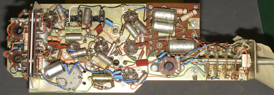
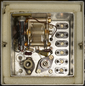
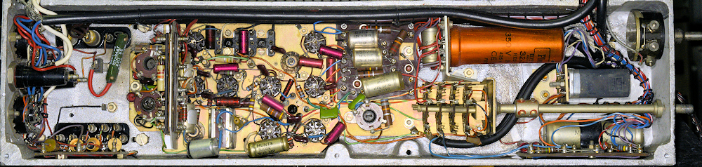
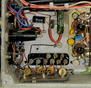
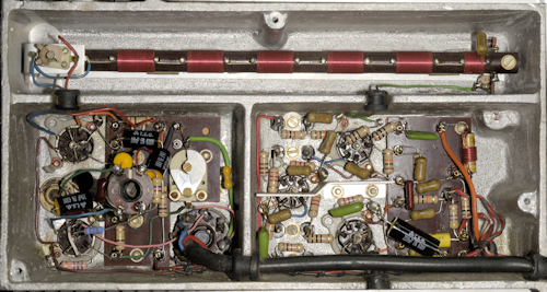
The original calibrator
If this were an RA17, we'd be looking at a somewhat simple power supply and a pair of RF pentodes pressed into action as audio amplifiers. Instead, since this is an MA79, the bulk of this space is occupied by a seemingly confusing conglomeration of valves. Welcome to the Calibrator!
Like the rest of the MA79, when you break it down, the Calibrator is less daunting than you might expect. As in the RA17, calibration at 100KHz intervals is standard. Then as in RA17s (known rather incongruously as the KL/GRR3011A) sold to The Netherlands, calibration is also offered at 10KHz intervals. Finally, there is also a 1.6MHz calibration position which is employed when adjusting the Fine Frequency control and acts on the 5.1MHz (10.2MHz) oscillator.
But the Calibrator is more than just a calibrator. In the MA79 the Calibrator is cunningly used to generate the 1.4MHz signal which is fed to the Modulator, and thus becomes a crucial part in the R.F. generating chain. Unlike in the RA17 etc. where the Calibrator is only switched on when required, the Calibrator in the MA79 is running all the time. More precisely, while the 100KHz divider runs 100% of the time, the 10KHz and 1.6MHz circuits only run when calibration is selected.
The 100KHz output is applied to V31 (EF91) where the 14th and 16th harmonics are extracted in L53 and L54 respectively. The output from L54 is used for performing the 1.6MHz calibration whilst the 1.4MHz from L53 is fed to the Modulator, V9 (EF91). I thinks its very clever ... and a spectrum analyser is a must when tuning L53 and L54.
As with the RA17, calibration is an aural thing, hence the headphones jack on the front panel, which might appear a bit odd on a transmitter, but is a whole lot easier than using the front panel meter (selected via the Meter Selection Switch). The Calibrator effectively has its own radio receiver comprising V33 (6AS6) and V32 (EF91) to make aural calibration possible ... also rather clever.
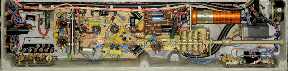
The new Calibrator, refurbished and installed.
At this point I did consider tackling the Power Supply, but thought it wiser to leave that to the end as the task would involve careful re-wiring to incorporate the three additional HT fuses. So ... on to the Modulator assembly!
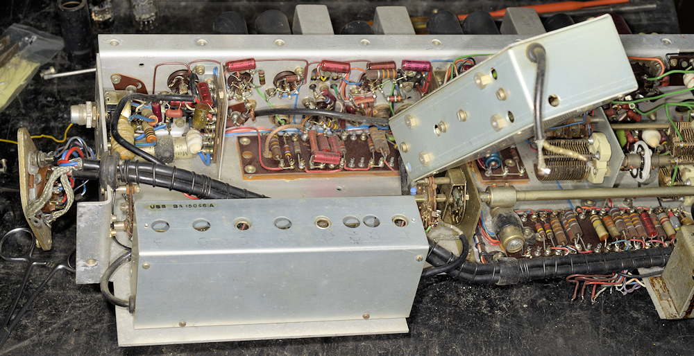
And its at this point of writing this article that I realise that I hadn't taken detailed pre-refurbishment photographs of the Modulator. So you will have to take my word regarding the following photograph.
The photograph above shows the Modulator assembly during re-work. As you can see, a previous owner had replaced the 12-pin Belling-Lee connector with an 8-pin Octal socket. This is the second time I have encountered the early 'discrete' style Sideband filters. Rather worryingly the USB filter is missing the cover over the holes, and the enclosed component designations have been scratched onto the body. I was able to confirm that the passband of both filters were the same, albeit one a mirror-image of the other, which did put my mind at ease. The LSB filter is temporarily removed to allow better access to the wafers of Switch SE which I have replaced with 4-way wafers so as to facilitate an external 1.4MHz input. There is a note on Fig. 6 in the manual which states that the EXT position is not available on the MA79A.
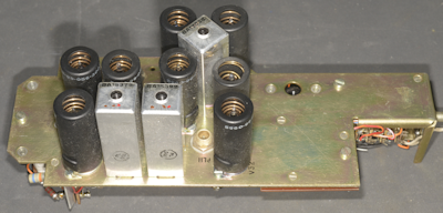
Whilst I was more or less happy with the sideband filters, the same could not be said for the 2MHz-3MHz Filter. This is the same filter found in the RA117. Unlike in the RA117 where this filter is mounted on the main chassis; in the MA79 it is attached to the rear of the Modulator Assembly ... and in order to remove the LSB filter, it is first necessary to completely dismantle the 2MHz-3MHz filter in order to gain access to two of the four retaining screws, which doesn't sound like a good mechanical arrangement to me.
2MHz-3MHz Filter on rear of Modulator
Three out of the seven coil-formers had suffered from age-related degradation. Historically, anywhere Racal have used this style of former, such as in the RA37, RA137 and RA237, today they will without doubt be brittle to the point of disintegrating. Recently I made a point of stocking up on new formers, but I wasn't expecting to have to replace so many. As it was, I was able to reassemble the filter and re-tune (where necessary) to the point that it met the spec.
Badly damaged filter
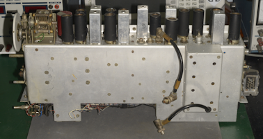
The photograph above shows the Modulator assembly after full refurbishment. I added a third wafer to Switch SC to accommodate the twisted red and violet pair of wires which is present on MA79s which feature the LA255. I still have to test the modulator, but not until I have fitted the three additional HT fuses. It is now time to tackle the power supply. Starting at the beginning ...
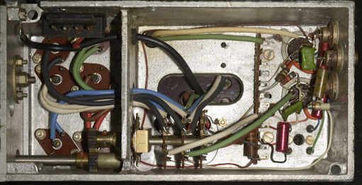
PSU mains-side before
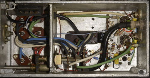
PSU mains-side after
As noted in an earlier photograph, the method of connecting this MA79 to the UK mains supply had been direct (no Plessey connector) and via and ancient 2-pin plug. If memory serves, these tended to be rated at a mere 2A. The flat-twin white wire was across the transformer primary and connected to two anonymous 4mm binding posts on the original rear panel assembly ... definitely not safe!
C199, 10nF
The 10nF Hunts paper capacitor(C199) across the transformer HT winding was missing, although its 'legs' were still present. I have yet to encounter an MA79 where this little capacitor has not previously exploded! I fitted one rated at 630V.
A 7W 27K enamelled wire-wound resistor has been added across the +250V rail. This appears to be part of the modification to add three additional HT fuses. As well as discharging the smoothing pack on switch-off, it also goes some way towards avoiding an initial excessively high voltage on this line at switch-on.
A 7W 27K enamelled wire-wound resistor has been added across the +250V rail. This appears to be part of the modification to add three additional HT fuses. As well as discharging the smoothing pack on switch-off, it also goes some way towards avoiding an initial excessively high voltage on this line at switch-on.
Load resistor, 27K, 7W
While still on the subject of the Power Supply. More PSU-related components can be found behind the front panel, between the ALC switch and the Mains switch. These include R196, 150R and C198, 100uF which relate to the -ve 25V line. And don't forget R161, 1K, 7W adjacent to the KHz VFO which is the dropper for the +200V line.
Finally we have C197, 32uF, the smoothing capacitor for the +200V line, which is nowhere near R161, but is adjacent to the tag-strip to which the Modulator assembly is wired. I have to wonder why so many of the PSU circuitry is seemingly distributed around the chassis haphazardly.
Admittedly, and inevitably, this all makes diagnosing faults that little bit more time consuming. Likely a necessity on account of the Calibrator taking up so much space. But this practice of distribution isn't limited to the physical. Take a look at the circuit diagrams ... in particular to Fig. 4 which Racal refer to as Ancillary Circuits. Its really the Power Supply, and I get the fact that all the module filter chokes etc. are shown together, but why have they not identified which module/circuit they each serve? Then note the inclusion of R183 at the bottom of the page. Would it not be more logical to show this resistor on Fig. 3? And surely D8, across RLA is shown the wrong way round?
Moving on ... time to put it all back together, re-wire the HT to accommodate the three additional fuses, and fit the LA255 ... but first, remember to change the two resistors on the end of the 30MHz LP filter on the output of the Harmonic Generator ... the KHz VFO module obscures the retaining screws.
And here I must make a confession. My re-draw of Fig. 4, to include the three additional HT fuses was originally totally wrong. I can't remember what I based that on, but I have now corrected the errors having carefully traced the wiring in the MA79H that is awaiting refurbishment. A link to the correct diagram, and others is at the end of this article.
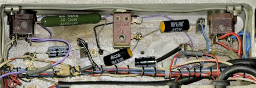
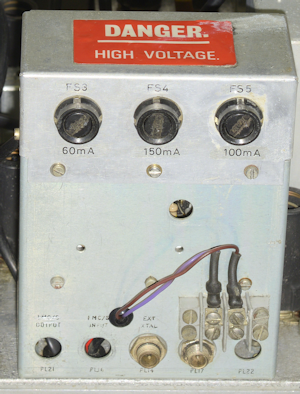
Rear Panel and Fuses
The LA255 is mounted on its side on the rear panel. The sub-chassis that carries the three additional fuses sits on top of the rear panel, sharing three of the screws securing the LA255. The terminal block with the brown and violet wires appears to be a feature when the LA255 is fitted. The violet wire is the -ve 25V line and the brown wire is connected to the junction of RLB, R56 and R55 ... so looks like a connection for a CW key.
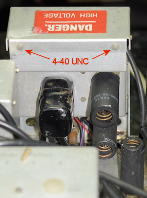
Here's a curious observation. All the screws on the MA79 are British BA threads, with the exception of the two screws securing the safety cover at the rear of the three additional fuses, which are 4-40 UNC ... why?
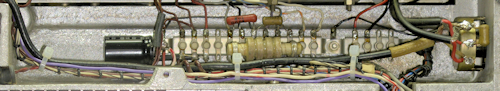
LA255 and Fuses
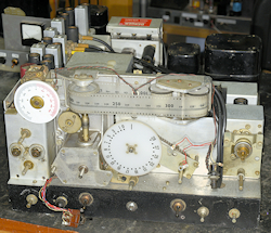
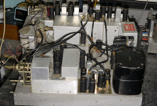
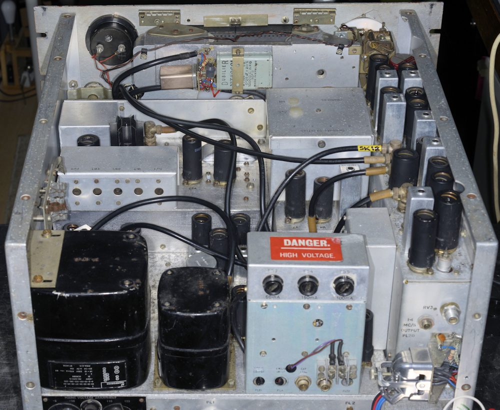
Here's a couple of photographs of the MA79, re-built, but still awaiting the front-panel. I still have to test the Modulator and refurbish the compartments under the main chassis. Testing of the Modulator assembly was deliberately left until now since it is easier to do as part of the whole MA79. This obviously assumes that the as yet un-refurbished parts are functional. These are the 1MHz Oscillator, Harmonic Generator, Harmonic Mixer and 2nd Mixer ... all of which I have confidence in.
First switch-on
As ever, after verifying no unusually low resistances between the various supply lines and chassis (0V), the MA79 was powered up via a variac. All looked good. The 1MHz Oscillator delivered a healthy sine-wave and there was clear evidence that the Harmonic Generator and Mixer were working by witnessing a healthy signal every MHz at TP2.The Knights oven in the centre of the main chassis was warming up, as was the dual oven on the Modulator assembly, and after several minutes I heard the reassuring 'thunk' of RLA switching off, indicating that the thermostat in Oven 1 was doing its thing. All was indeed looking good.
The best way to test the Modulator assembly is to follow the procedure in Section 2 of the manual ... probably start at chapter 6 entitled F.S.K. and Fine Frequency Calibration. This tests and verifies two crystal oscillators (10MHz and 10.2MHz). Although a tad laborious in places, everything aligned nicely. I skipped chapters 7 and 8 since I had aligned the MHz and KHz VFOs earlier, although I did verify that all three Calibrator settings were functional.
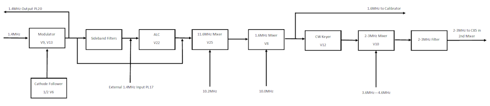
Simplified block-diagram of the Modulator Assembly
The method in the manual for aligning the various mixers in the Modulator assembly is typical of a time when spectrum analysers were a luxury ... not commonly found on a technicians bench. Again, my little TinySA Ultra made short work of assisting in identifying and discerning wanted and un-wanted mixing products throughout the chain of three mixers (see above diagram). For measuring the output power of the MA79G, I use a Racal-Dana 9100 Absorption Wattmeter with my Rigol DSA915TG connected to the monitor output which is -23dB on the input.
I was delighted to see that this MA79 was happy to deliver more than enough CW signal than that specified over the range of 1.5MHz to 30MHz. I verified that the Pilot carrier could be varied of a range of -6dB to -26dB and I was beginning to think that this might be the best MA79 that I had encountered ... until I realised that something was not right with the DSB (AM) modulation.
In the MA79, the modulation signal is buffered by V6B, configured as a cathode-follower. This signal is applied to the centre-tap of the L18B, where it modulates the signal developed across L18. I was monitoring the output of the MA79G on a spectrum analyser and was barely managing to get more than 30% amplitude modulation. The gain of a cathode-follower is generally slightly less than 1. On this occasion I was seeing close to 20dB of attenuation. Something was clearly amiss with the cathode-follower. The valve, a 12AT7 was checked on my VCM163 and confirmed to be well within spec. so the problem had to be with the wiring, or a failed component. What I did discover was that the voltages on the grid and cathode of V6B were completely wrong. The cause of this was not what I expected.
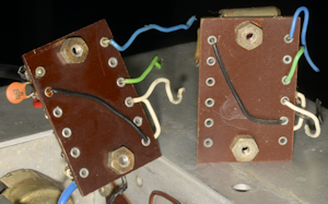
Wrong wiring on left - correct wiring on right
The problem was definitely linked to the small tag-board on which I had replaced everything except the choke, and that checked out OK. So what else could be wrong. I then remembered that having stripped down two MA79s, I had a spare cathode-follower tag-board. I removed each of them from their little sub-chassis, and there in front of me was the cause of much head scratching. Note the black wire on the reverse side. This is a classic manufacturing error. When the board had been assembled, the black wire had been soldered in place. Then before the rest of the wires and components were added, the board was inadvertently turned through 180 degrees. Very likely a distraction caused by a tea-break. Remember, this was originally an MA79A where the Modulator was not used ... thus the wiring error was never discovered until now. Easily rectified by changing the placement of the black wire.
So that resolved the modulation level issue ... but moving, on I found a serious issue associated with the output power when LSB or USB was selected. I was seeing a drop in excess of 20dB when either sideband was selected. Output power remained very healthy when DSB was selected. Remember, the sideband filters in this MA79 were the early discrete component type. However I did have a seriously stripped down modulator assembly complete with two filters of the later encapsulated type. Would these both be good? Comparing the filters, like for like, although the shape-factor was more or less identical, for some reason the older filters were presenting at least 20dB more attenuation than the encapsulated type. I substituted the encapsulated USB filter for the discrete filter and found that the power level for that sideband was restored. Doing the same with the other filter restored that sideband power also. What is puzzling is that the shape and pass-band of the discrete filters is very similar to that of the encapsulated ones ... they just incur a whopping extra 20dB of loss. Obviously, I decided that the best solution here was to swap out the discrete ones and fit the newer encapsulated ones. But to do that, on account of the mounting method of the older filters, the entire Modulator Assembly would need to be detached.
The issue here is one of interference. Whereas the older filters mount directly onto the sub-assembly, the newer ones are supported on individual 6BA pillars, which ultimately means that if one of them should fail, and I have encountered one failed encapsulated filter, they are relatively simple to replace. Replacing a discrete filter is another matter ... especially if an LA255 is fitted!
To gain access to two of the screws securing the LSB filter, the 2MHz to 3MHz filter needs to be literally dismantled. The lid needs to come off then the filter board needs to be lifted off its supports ... just to get at two screws. However before the lid of the filter can be eased off, the LA255, and anything else attached to the inside of the MA79 rear panel needs to be removed first ... tedious, but not necessarily difficult.
Having done this, I removed the old filters, fitted the eight 6BA pillars and fitted and wired in the new encapsulated filters. Since I knew these worked I continued to re-fit the LA255 etc. and powered up the MA79G ... NOTHING! Or more accurately, no RF output, on any mode. Off came the LA255 etc, off came the filter, and sure enough, there's the fault. The inner of the output coax had snapped off. Easily fixed, but still no RF output. This time I discovered that the much thinner input coax inner had snapped off. This time though, I removed the filter completely and tested it using the tracking generator on my Rigol analyser. This test is not ideal since the Rigol is a 50-ohms device and the filter impedance is more like a few thousand ohms. But it does give a go-no-go result. In this case, even with both coaxes securely repaired, nothing was getting through the filter.
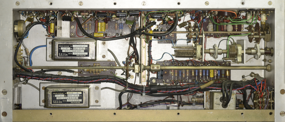
The refurbished Modulator Assembly now with encapsulated filters.
With a new capacitor fitted, it was like a switch had been flipped ... and the MA79G was again singing very nicely.
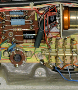
Now back to the refurbishment process, and the three remaining under-chassis compartments.
Left: Everything in this photograph looks just like what you'd expect in an RA17, except for a couple of differences. The obvious difference is the presence of the Octal connector for the temperature-controlled oven. The other difference is that despite the crystal oscillator circuit being a Colpitts, as in the RA17, the circuit in the MA79 is somewhat different. Also note that the trimmer capacitor is almost fully meshed.
The circuitry in the Harmonic Mixer compartment is identical to that in the RA17.
Left: I should have pointed out earlier that the original wiring in the Oscillator compartment had been configured for a Lavoie oven. Since I fitted a Knights oven, changes were required; hence the pink wires. I also added a 15pF silvered mica capacitor across the trimmer capacitor so that it is no longer fully meshed when adjusted for exactly 1MHz. Initially I thought that two of the ceramic 1nF capacitors in the Harmonic Mixer compartment had been changed, but it turns out that the two green silvered mica capacitors at the bottom are still 1nF.
Right: Looking just like the 2nd Mixer in the RA17, this is effectively the second-last mixer in the MA79, although the circuit diagram calls it the 2nd Mixer. This circuit effectively operates in reverse to its RA17 counterpart. It mixes the 2-3MHz signal from the modulator assy. with the 37.5MHz from the Harmonic Mixer to produce a signal between 39.5MHz and 40.5MHz.
Right: Job done! No issues encountered with this circuit. All compartments and modules fully refurbished ... all 'at risk' Rs and Cs replaced and an MA79G that I have full confidence in. All that is left is to make up a suitable Mains cord with a Plessey connector and look out a mating connector for the 12-way Belling-Lee plug at the rear.
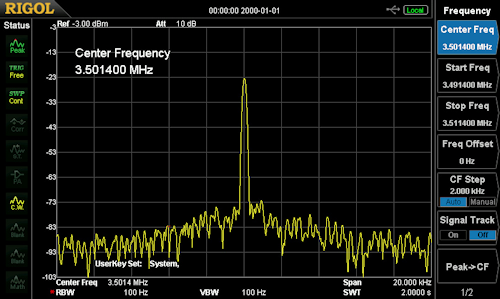
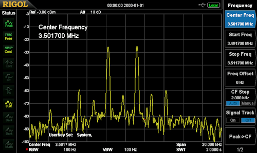
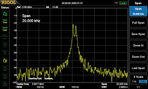
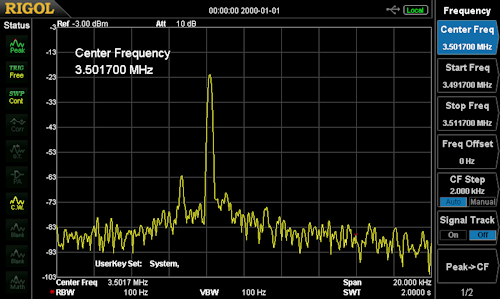
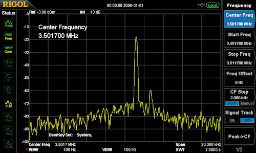
Here are some screen grabs from the Spectrum analyser of the MA79G operating ...
CW Signal
Amplitude Modulation
FSK Signal
Lower Sideband
Upper Sideband
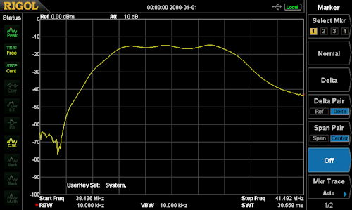
The 40MHz Bandpass Filter
Having not made any adjustment to the 40MHz Bandpass filter, I used the tracking generator on the Rigol to demonstrate the shape and integrity of the filter ... absolutely spot-on! So I just left it. When something is working well, best leave it alone.
Finally two end-result photographs of the MA79G ...
Cleaned up front panel and knobs re-whited
Shiny!
And as promised ... links to the updated and corrected diagrams ... Technical Manual ... Includes section on the MA284 and a circuit diagram for the LA255.
Block diagram for MA79G (Fig. 1)
Block diagram for MA79H (Fig. A-1)
MA79G Calibration and Output Stages, (Fig. 3) ... updated May 2025
MA79H Calibration and Output Stages, (Fig. A-5) ... updated May 2025
MA79G Modulation and IF Stages, (Fig. 2) ... Updated May 2025
MA79H Modulation and IF Stages, (Fig. A-4) ... Updated May 2025 ... Figures 2 and A-4 have been modified to reflect Change No. 2, Issue 6, June 1971. Included in the manual. Note the reference to a -35V line. I have kept to this reference when making changes to the circuit diagrams. This may be a genuine 'typo', or it may be a 'nod' to the fact that the -25V line is nominal and is actually closer to -35V at the best of times.
MA79 Ancilliary Circuits, (Fig. 4) ... updated March 2025
MA79 Ancilliary Circuits, (Fig. 4), modified ... Updated March 2025 ... Modified to reflect units where three additional HT fuses have been fitted, notably when the LA255 is fitted.
Next post in the series: Transmitter Drive Unit Type MA79H