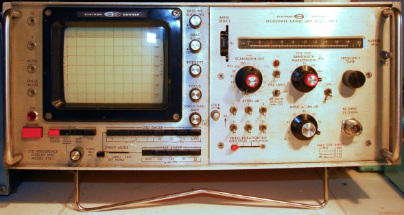
Systron Donner Spectrum Analyzer Type 809-1
16 minute read
This post is part of the series 'Systron-Donner Type 809-1':
Not having a 100uF capacitor to hand, I fitted a high-spec 68uF one instead, with no obvious detrimental consequences. I did find a completely u/s 470uF tantalum (I think) capacitor on the Sweep and Vertical Amplifier board. One lead had completely corroded away! I replaced it with a modern aluminium type. This capacitor could well have failed a long time ago. It is the timing capacitor responsible for the slowest horizontal sweep and not a setting that I have ever used. It was partially hidden by the small timing board in the photograph below right. Having ascertained that all the power supplies were ‘good’, it was now time to investigate the RF-Unit.
The photograph on the left shows the repaired 260MHz amplifier reinstalled. The long white SMB lead is the original and is presumably that length so as to allow the two halves of the RF-unit to be operated when ‘split’.
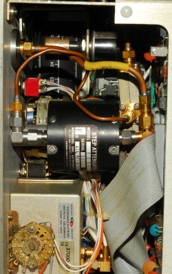
So I now had my Spectrum Analyzer back. But what about the faulty input attenuator? I was able to split it and verify that one of the elements is damaged. I had an idea that I might have a solution. I found a couple of rotary step attenuators salvaged from scrapped test equipment. One turned out to be 1dB steps, so that was a non-starter. The other was 60dB in 6 steps. It was a real 3D ‘jigsaw puzzle’ fitting it in. The only down-side of the Weinschel against the Widwest attenuator is that it is ‘backwards’ … i.e. 0dB is the final position as opposed to the first.
However, this solution proved to be problematic. Such was the tight squeeze that the rear connector on the attenuator actually pushed the adjacent PCB against the bulkhead. causing intermittent short-circuits. Also, I discovered that the 0dB position was intermittent. This might actually have been due to stress applied by the tight squeeze. Thus I have reverted to the original, but faulty attenuator. So I may build the Weinschel attenuator into an external box that can be connected up to the front of the analyzer. There is no law that says that the attenuator must be internal.
Simply click on the links below to either open (in the case of the manual and Items List) or download the zip file.
Next post in the series: Systron Donner Spectrum Analyzer Type 809-1 re-fit
- Systron Donner Spectrum Analyzer Type 809-1
- Systron Donner Spectrum Analyzer Type 809-1 re-fit
- Systron Donner Spectrum Analyzer Type 809-1 - Solving the Frequency Calibration Issue
March 2015
Actually, 809-1 is the designation of the RF section on the right. The manual describes it as a model 762-1. Alternatively it can be referred to as ‘Microwave Spectrum Analyzer type AN/USM-394’ which I believe is its US Military designation.
This piece of hardware has been in my possession since 1985, when my boss at the time said to me “If you can put the boot of your car between the back door and the skip, I’ll give you a hand with the old analyser”. At the time it was probably 10 or 12 years old and was technically MoD property, having been purchased against a one-time top-secret contract. I first came in contact with it in 1979 when its sole purpose was to monitor 2 signals in the region of 9GHz and to verify that one was sweeping across the other. This task was done inside an anechoic chamber with the lights out because the trace intensity was so poor. By 1985 the test method had been refined and the analyzer consigned to storage since it was MoD property. At the time there was an MoD policy which deemed items of test equipment over 10 years old to be classed as ‘end of life’. The thinking behind this policy was based on the premise that they would become uneconomical to service or repair; thus they were disposed of and/or replaced. It was the belief of many at the time that this old analyser was faulty anyway … the fact that it had to be viewed in a darkened room. With the analyzer safely in my car I then paid a visit to the Calibration Lab to retrieve the service manual and showed the technician the paperwork which proved that the analyzer had been scrapped. Back home and with the help of the manual, I found an internal adjustment that turned up the volts on the CRT and the trace has been nice and bright ever since!
The analyzer came in very handy when I modified an Injection-Locked 9.6GHz oscillator for 10.224GHz. The fact that I had done this at home intrigued my boss who asked how I had managed it. When I told him that I had used the old Systron-Donner analyzer he was even more intrigued since he had assumed that I had stripped it for parts. He was even more surprised to learn that all that had been required to get it into working status was to turn up the HT. I think at that point he may have uttered something about the competence of the Cal-Lab technician.
Then about 2 years ago (2013) I noticed that it was ‘deaf’. I was working on a 10GHz transverter for a friend and discovered that the sensitivity of the analyzer had dropped to the extent that it was unusable. It then gathered dust in my radio room for about a year before being ‘shunted’ out into the hall-way to sit alongside other miscellaneous non-working items. Earlier this week (March 2015), I decided to embark upon a systematic approach to identifying the problem.
What sets this analyzer apart from others of its time is the fact that its frequency coverage is so wide. It covers 10MHz thru’ 12.4GHz in 5 ranges without the need to change any ‘plug-Ins’. (The model 809-2 increases this range up to 40GHz in 3 more ranges employing external wave-guide mixers). Perhaps the most popular Spectrum Analyzer of the early 1980s was Hewlett Packard’s one based around the 141T display, requiring a range of RF and IF plug-ins to give a similar range of coverage. The HP equipment with its calibrated display can be used to make relatively accurate power measurements. In contrast, the Systron-Donner analyzer cannot be used in this way since it is not possible to set up a reference level on the display. In essence, only relative measurements can be made. Thus the Systron-Donner spectrum analyzer is more accurately described as a ‘field’ instrument rather than a laboratory instrument. Credit must however be given to Systron-Donner for coming up with an instrument with such a wide frequency coverage in a single unit and keeping it relatively small (smaller than the 141T mainframe) … this was over 40 years ago! … mid 1970s.
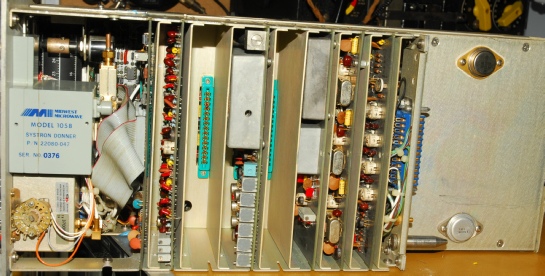
But my analyzer was now faulty … What had failed? Essentially everything appeared to be working … it was just VERY deaf. When you pull the 809-1 plug-in out it can appear a bit daunting since the RF-unit is fully enclosed. It is only when you turn it upside down that you read the dismantling instructions. Essentially, the RF-unit splits into 2 parts; the RF-deck and the IF-section. The first thing I checked was the input attenuator since I already knew that one of the positions was u/s. Whilst I did confirm a ‘dead’ element in the step-attenuator, this was not the cause of the chronic deafness.
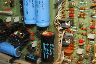
Turning my attention away from the complicated RF stuff, I investigated the power supplies located on the underside of the display section. Everything was in order, although the 100uF capacitor on the 200V line appeared to have sprouted a ‘wort’ (see below).
This piece of hardware has been in my possession since 1985, when my boss at the time said to me “If you can put the boot of your car between the back door and the skip, I’ll give you a hand with the old analyser”. At the time it was probably 10 or 12 years old and was technically MoD property, having been purchased against a one-time top-secret contract. I first came in contact with it in 1979 when its sole purpose was to monitor 2 signals in the region of 9GHz and to verify that one was sweeping across the other. This task was done inside an anechoic chamber with the lights out because the trace intensity was so poor. By 1985 the test method had been refined and the analyzer consigned to storage since it was MoD property. At the time there was an MoD policy which deemed items of test equipment over 10 years old to be classed as ‘end of life’. The thinking behind this policy was based on the premise that they would become uneconomical to service or repair; thus they were disposed of and/or replaced. It was the belief of many at the time that this old analyser was faulty anyway … the fact that it had to be viewed in a darkened room. With the analyzer safely in my car I then paid a visit to the Calibration Lab to retrieve the service manual and showed the technician the paperwork which proved that the analyzer had been scrapped. Back home and with the help of the manual, I found an internal adjustment that turned up the volts on the CRT and the trace has been nice and bright ever since!
The analyzer came in very handy when I modified an Injection-Locked 9.6GHz oscillator for 10.224GHz. The fact that I had done this at home intrigued my boss who asked how I had managed it. When I told him that I had used the old Systron-Donner analyzer he was even more intrigued since he had assumed that I had stripped it for parts. He was even more surprised to learn that all that had been required to get it into working status was to turn up the HT. I think at that point he may have uttered something about the competence of the Cal-Lab technician.
Then about 2 years ago (2013) I noticed that it was ‘deaf’. I was working on a 10GHz transverter for a friend and discovered that the sensitivity of the analyzer had dropped to the extent that it was unusable. It then gathered dust in my radio room for about a year before being ‘shunted’ out into the hall-way to sit alongside other miscellaneous non-working items. Earlier this week (March 2015), I decided to embark upon a systematic approach to identifying the problem.
What sets this analyzer apart from others of its time is the fact that its frequency coverage is so wide. It covers 10MHz thru’ 12.4GHz in 5 ranges without the need to change any ‘plug-Ins’. (The model 809-2 increases this range up to 40GHz in 3 more ranges employing external wave-guide mixers). Perhaps the most popular Spectrum Analyzer of the early 1980s was Hewlett Packard’s one based around the 141T display, requiring a range of RF and IF plug-ins to give a similar range of coverage. The HP equipment with its calibrated display can be used to make relatively accurate power measurements. In contrast, the Systron-Donner analyzer cannot be used in this way since it is not possible to set up a reference level on the display. In essence, only relative measurements can be made. Thus the Systron-Donner spectrum analyzer is more accurately described as a ‘field’ instrument rather than a laboratory instrument. Credit must however be given to Systron-Donner for coming up with an instrument with such a wide frequency coverage in a single unit and keeping it relatively small (smaller than the 141T mainframe) … this was over 40 years ago! … mid 1970s.
But my analyzer was now faulty … What had failed? Essentially everything appeared to be working … it was just VERY deaf. When you pull the 809-1 plug-in out it can appear a bit daunting since the RF-unit is fully enclosed. It is only when you turn it upside down that you read the dismantling instructions. Essentially, the RF-unit splits into 2 parts; the RF-deck and the IF-section. The first thing I checked was the input attenuator since I already knew that one of the positions was u/s. Whilst I did confirm a ‘dead’ element in the step-attenuator, this was not the cause of the chronic deafness.
Turning my attention away from the complicated RF stuff, I investigated the power supplies located on the underside of the display section. Everything was in order, although the 100uF capacitor on the 200V line appeared to have sprouted a ‘wort’ (see below).
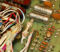
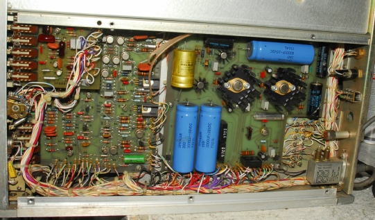
Not having a 100uF capacitor to hand, I fitted a high-spec 68uF one instead, with no obvious detrimental consequences. I did find a completely u/s 470uF tantalum (I think) capacitor on the Sweep and Vertical Amplifier board. One lead had completely corroded away! I replaced it with a modern aluminium type. This capacitor could well have failed a long time ago. It is the timing capacitor responsible for the slowest horizontal sweep and not a setting that I have ever used. It was partially hidden by the small timing board in the photograph below right. Having ascertained that all the power supplies were ‘good’, it was now time to investigate the RF-Unit.
Above - Corroded 470uF Tant.
Right - Power Supplies and Sweep & Vertical Amplifier board.
Right - Power Supplies and Sweep & Vertical Amplifier board.
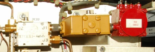
Ask anyone who has experience with RF Spectrum Analyzers and they will tell you that the worst-case scenario failure is a failed First-Mixer. In Hewlett-Packard units such as the the HP 8555A (mentioned earlier) the diode is bonded to a ceramic substrate and locked away in a sealed box. Systron-Donner employed a completely different style of mixer assembly. In their case, the diode itself is a replaceable component accessible from outside the unit. Thus it is easily replaced if blown. The diode is accessible through a hole in the unit side-wall … see photograph below.
But it wasn’t the mixer-diode that was faulty. Not only was the analyzer deaf, but there appeared to be a frequency discrepancy. Thus I concluded that one of the two Yig-Oscillators might be off frequency … and if off frequency, they might also be delivering a lower than normal output. That was the notion anyway … hmmm?
The service manual contains a very comprehensive fault diagnosis series of flow-charts covering no less than six A3-size fold-out pages. However there is a problem … whoever wrote them used the 809-2 with its external mixer drive socket in mind. So when I got to the bit where it tells me to measure the level of first LO drive, I don’t have the appropriate front-panel connector. My only option was to measure the level somewhere inside the RF-deck. This introduced another issue, in that the RF-unit needs to be inside the main assembly since I don’t have the necessary extender cable … not to mention that running the RF-unit ‘split’ would be a near impossibility anyway. However, as Baldric would (almost) say, ‘I had a cunning plan’. Removing the input step-attenuator was relatively easy. This left two good size holes in the front panel since the RF-Input connector is integral with the attenuator. It was then simply a case of attaching one end of an SMA lead to the output of the second LO Yig or in the case of the first LO Yig, the associated isolator and feeding the other end out through the hole where the N-type connector once fitted. Off course the whole assembly needs to be disassembled and reassembled each time.
The service manual contains a very comprehensive fault diagnosis series of flow-charts covering no less than six A3-size fold-out pages. However there is a problem … whoever wrote them used the 809-2 with its external mixer drive socket in mind. So when I got to the bit where it tells me to measure the level of first LO drive, I don’t have the appropriate front-panel connector. My only option was to measure the level somewhere inside the RF-deck. This introduced another issue, in that the RF-unit needs to be inside the main assembly since I don’t have the necessary extender cable … not to mention that running the RF-unit ‘split’ would be a near impossibility anyway. However, as Baldric would (almost) say, ‘I had a cunning plan’. Removing the input step-attenuator was relatively easy. This left two good size holes in the front panel since the RF-Input connector is integral with the attenuator. It was then simply a case of attaching one end of an SMA lead to the output of the second LO Yig or in the case of the first LO Yig, the associated isolator and feeding the other end out through the hole where the N-type connector once fitted. Off course the whole assembly needs to be disassembled and reassembled each time.
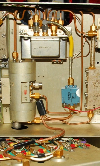
1st LO Yig (the red unit)
Tedious as it was, it worked rather well. I measured the power levels on my HP 436A Power meter and measured the frequency of each of the two Yigs. Both were in spec. So the fault lay somewhere else. One thing for certain was that it was not band-related. If it wasn’t in the RF-deck, then it was in the IF-section; in the 3rd or 4th IFs.
2nd LO Yig
The third and fourth IFs are 60MHz and 6.5MHz respectively. The non-availability of any form of extender meant that chasing a fault on one of the boards in the IF-section was going to be a nightmare, so I still held out hope that the fault was still on the RF-deck. The first and second IFs are on the RF-deck. The frequency of the first IF is dependant on what band is selected, so that ruled that one out, leaving only the second IF which is 260MHz.
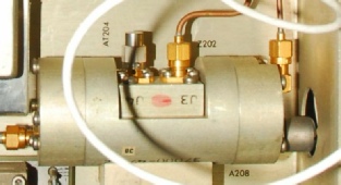
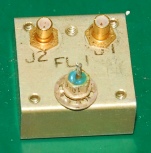
The second IF (260MHz) amplifier is a little inconspicuous milled aluminium enclosure next to the coupler after the isolator on the output of the first LO Yig. Could this be the faulty item I was searching for? I could test it easily by connecting it up to my Network Analyzer and verify if it was working, but I would first have to make up a pair of SMA to SMB leads. I had a better idea.
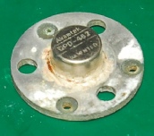
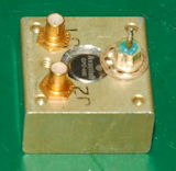
I had a brand-new Watkins-Johnson gain-block which I connected up to my Network Analyzer and verified the gain to be around 13dB. The supply voltage was the same (+15V), so wiring it into the RF-deck was not going to be a problem. However the W-J amp used SMA connectors so I had to be creative in connecting up the output! BINGO! It worked … Or more precisely, the Spectrum Analyzer now worked. I had a nice ‘fat’ trace on the display for +10dBm at 400MHz with 30dB of input attenuation. The photograph on the left shows the ‘belt and braces’ lash-up, but it worked. I could have left it like it was and lived with it, but I suspected that the failed amplifier might be an Avantek MMIC and I was sure I had one tucked away somewhere. I put it on my VNWA (Vector Network Analyzer) and confirmed that it was now an attenuator (about 30dB). It was an easy matter getting the PCB out of the enclosure. I was right, it was indeed an Avantek GPD-462. See the above photograph. Note the corrosion around the base of the can. I found my ‘spare’, a GPD-405 which is essentially a beefed up 462, capable of delivering higher power. I cleaned up the tiny PCB and fitted the GPD-405 only to discover that the can was slightly ‘taller’ … so it was necessary to drill a hole right through the enclosure to allow it to fit. See the photograph below.
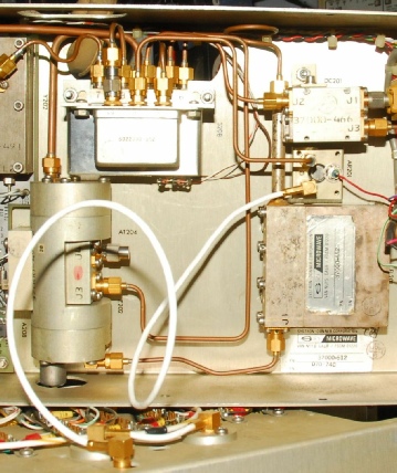
The photograph on the left shows the repaired 260MHz amplifier reinstalled. The long white SMB lead is the original and is presumably that length so as to allow the two halves of the RF-unit to be operated when ‘split’.
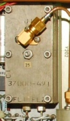
So I now had my Spectrum Analyzer back. But what about the faulty input attenuator? I was able to split it and verify that one of the elements is damaged. I had an idea that I might have a solution. I found a couple of rotary step attenuators salvaged from scrapped test equipment. One turned out to be 1dB steps, so that was a non-starter. The other was 60dB in 6 steps. It was a real 3D ‘jigsaw puzzle’ fitting it in. The only down-side of the Weinschel against the Widwest attenuator is that it is ‘backwards’ … i.e. 0dB is the final position as opposed to the first.
However, this solution proved to be problematic. Such was the tight squeeze that the rear connector on the attenuator actually pushed the adjacent PCB against the bulkhead. causing intermittent short-circuits. Also, I discovered that the 0dB position was intermittent. This might actually have been due to stress applied by the tight squeeze. Thus I have reverted to the original, but faulty attenuator. So I may build the Weinschel attenuator into an external box that can be connected up to the front of the analyzer. There is no law that says that the attenuator must be internal.
Above - underside of IF-section. The faulty attenuator is the grey cube on the left.
Right - Weinschel attenuator ‘shoe-horned’ into place with bulkhead mounting N-SMA adaptor as input connector. This solution was later abandoned.
Right - Weinschel attenuator ‘shoe-horned’ into place with bulkhead mounting N-SMA adaptor as input connector. This solution was later abandoned.
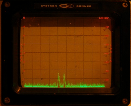
With the analyzer working again I have to admit that I’m of the opinion that it is now performing better than before. The photograph on the right shows two signals in the region of 7MHz as received on my Inverted-V connected directly to the analyzer input; no external amplifier. Also, when this photograph was taken, the mast was down at half-height because of gale-force winds. So the average height of the antenna would be around 3m. In the past I had only been able to see signals like this with an external wide-band amplifier at the analyzer input. Note that this is also below 10MHz; the analyzer’s specified lower limit. There is a drop-off in performance at the lower end of it’s frequency coverage but only about 6dB. Previously the drop-off was dramatic, with sensitivity below 100MHz being about 20dB down on that at 1GHz. I replaced the faulty GPD-462 with a GPD-405. Both are spec’d at 13dB gain. I measured the gain of the GPD-405 as 14dB. As previously said, the GPD-405 is a more robust device, capable of delivering a higher level of signal with greatly improved noise figure. However these enhancements would not produce the perceived performance improvement. Thus I have to conclude that the 260MHz amplifier had been faulty for some time and only failed completely two years ago.
Why the need for a Spectrum Analyzer anyway? Used correctly, a spectrum analyzer can show the user the exact spectral output of a transmitter, amplifier or oscillator. Even sophisticated power meters, like my HP 436A are broad-band and do not distinguish between wanted and unwanted signal content. Connecting a badly tuned oscillator/multiplier to a power meter might give an indication of 10mW, but half of that or more might be unwanted harmonics and spurii. This is where the RF spectrum Analyzer excels. It allows the user, at a glance, to check if unwanted signal content is present. I don’t know what the rules are these days, but back in 1976 when I applied for my Amateur Radio licence there was a section on the form where I had to list what equipment (including model number and serial number, if known) I intended to use to ensure that my transmitter was not likely to interfere with other services. Because of where I worked at the time, I was able to list quite a lot of RF test equipment including a Hewlett-Packard HP8558B spectrum analyzer, which I remember drifted very badly. In the 1930s it was a different story. The following is a quote from Wireless Transmission for Radio Amateurs published in 1938 …
‘Applicants must satisfy the Postmaster General as to their qualification and intention to conduct experiments of scientific value or public utility. If scientific investigation is intended they should be certified as competent investigators by a Government Department or some recognized scientific body. Authority to use wireless sending apparatus, even with an artificial aerial can be granted only if the nature of the proposed experiments and other circumstances warrant that course.’
Basically, one had to demonstrate the proposed experiments to a representative from the Post Office. … How times change!
Downloadable Service Manual
Systron-Donner became part of Thorn-EMI, possibly as long ago as 1980. Consequently replacement parts and manuals are hard to come by. So when I began writing this piece, I envisaged that it would only be a matter of time before someone asked for a copy of the manual. So I have made it available for download. It is a copy of a copy so the quality is not brilliant. The sections that are scored out are my doing (30 yrs ago) and refer to the -2 version.Simply click on the links below to either open (in the case of the manual and Items List) or download the zip file.
Operation and Service manual: PDF of 121 pages, 50MB
Schematics and ‘pull-outs’: Zip file of 25 Jpegs, 6MB
Items List: PDF of 79 pages, 26MB
Schematics and ‘pull-outs’: Zip file of 25 Jpegs, 6MB
Items List: PDF of 79 pages, 26MB
Next post in the series: Systron Donner Spectrum Analyzer Type 809-1 re-fit