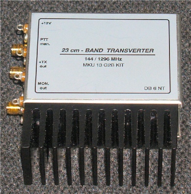
DB6NT 1.3GHz Transverter MKU 13G2B kit
11 minute read

July 2009
But first ...
My first 23cm transverter, bought at the Scottish VHF Convention in 1980 was the well known MMT1296 from Microwave Modules. It cost just under £200, which in 1980, was a serious sum of money. The thing was, and this is what attracted me to it at the time; there was nothing like it on the market, and it was British. Back then, if you wanted to get onto 23cm, you had to build it yourself. It was an all-bipolar design too; GaAsFETs were then still too expensive. The receive sensitivity and noise figure was adequate at best and the power output was a cool 0.5W. All this was crammed into two die-cast boxes, each the size of a then standard Microwave Modules transverter. I threw together a corner-reflector and dipole and managed a QSO across Edinburgh with Brian GM8BJF. My first microwave contact!
The ‘heady’ 0.5W was increased to 7W using six 2N5944 UHF transistors! This was a design published in DUBUS and employed 2 in parallel driving 4 in parallel. Real microwave transistors were still not within my budget. I could now manage the occasional QSO on 23cm up to the Aberdeen area . Then in 1989, I managed to work Karl SM6HYG!
In 1996 I embarked on a 13cm transverter based on DB6NT's article published in DUBUS. It was when sourcing the components for this that I decided to have a go at Michael's tiny 23cm transverter that had been published in DUBUS 4/92. My version of the DB6NT MK1 23cm transverter varied from that published, in that I used a Mini-Circuits SAM-5 Mixer as opposed to the hard to find Synergy one. To date, this tiny transverter has given me years of trouble-free operation as the heart of my 23cm station. It's MGF1302 front-end is not as sensitive and certainly nowhere near as quiet as today's HEMTs but back in 1992 it was more or less state-of-the-art.
In 2004, Kuhne Electronic eventually upgraded this little beauty and made it available in the shape of the MKU13G2 with an improved front-end employing an NE32584 and completely solid-state IF switching whilst retaining the Mitsubishi M67715 RF PA.
Then, in May this year (2009) the MKU13G2B was released as a kit and I decided it was time to upgrade! Functionally the G2B is identical to its predecessor. However, the most noticeable difference between the two is in the PA circuit where the INA10386 is replaced with the newer ERA-3 from Mini-Circuits and the M67715 has been replaced with a pair of monolithic gain blocks: a GALI-4 by Mini-Circuits driving an AH102A by Watkins-Johnson. The output power is now only 400mW as opposed to 1.2W. (This reduced power output may be a minor inconvenience to some). In the receive chain, the front-end is now an MGF4918D HEMT and the INA03184 MMIC has been replaced with an ERA-8. The mixer remains the same Mini-Circuits type ADE-5. On the IF switching side, one of the BAR64-03W PIN-diodes has been changed to an HSMP-3380, presumably to accommodate higher RF drive levels (up to 3W now as opposed to 1W.) Changes have also been made to the DC switching circuitry which now includes built-in sequencing ... a nice touch!
I think this is still the world's smallest 23cm transverter (and has been since 1992!) ... and interestingly enough it costs less than my MMT1296 did back in 1980. OK, you have to build it yourself, but that's where the fun is.
I should point out that between the G2 and the G2B, Kuhne released the G3 which has a built in PLL for locking to an external 10MHz source. The G3 is not however, available as a kit.
The MKU13G2B Kit:
This is not my first Kuhne Electronics kit. I have previously built transverters for 13cm and 9cm, so I was looking forward to working on the 23cm kit. Kuhne make the manuals for their kits freely available for download so I had already read through it before the kit arrived. I knew what to expect. Typical of German efficiency, the components are all pre-packed in two 'hobby boxes', for want of a better description. The semiconductors, connectors and larger items like helical filters etc are supplied in the larger of the two with all the smd Rs and small Cs in the smaller one. My wife likes the latter for keeping her ear-rings in!
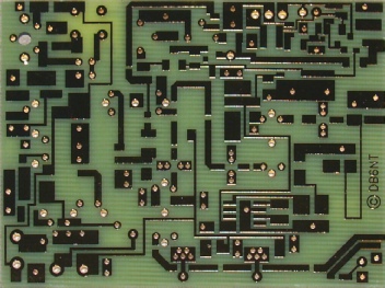
Gold-plated precision-etched PCB
As it says in the manual, this is not a kit for beginners. For one thing, the tin-plate box first needs to be soldered together. This is best done after the PCB is 'trimmed' (small fillets need to be filed so as to accommodate the overlaps where the case sides join). I also like to mark and drill all the necessary holes prior to soldering the case together ... this is just my preference though. Also, like all DB6NT transverters, this kit relies heavily on surface mounted components which require a steady hand and some degree of 'special' tools. A 'pencil tip' soldering iron is a must, as is super-fine solder (SWG34) ... which brings me to a 'thorny' subject ... 'the curse of RoHS'. I haven't previously mentioned it but the PCB is gold-plated. And you could be forgiven for thinking that this is to ensure low resistance tracks and that the board does not deteriorate over time, both of which are valid. However, it is more than likely that this is actually one of the good things to come out of RoHS, since a board 'tinned' with lead-free solder would look terrible. I don't even know if you can plate a board with that hideous stuff! If you want a board full of dry joints, then use lead-free solder! If you want the figures, lead-free solder is 99.8% Tin, 0.2% Copper. Tin is actually more dangerous than lead, since a simple cut from a piece of sharp tin can lead to blood poisoning. Lead, on the other hand needs to be ingested to cause you lasting harm. However EU rules demand that marketable products be lead-free . . . and rules are to be obeyed. I used good old fashioned SWG34 60/40.
I actually used two different soldering irons since I find that the pencil tip bit doesn't quite heat up the 'lands' that are through-plated to the ground-plane and are in close proximity to the side-walls. For these problematic 'lands' (or pads), I use a 'standard' bit.
There is an assembly order suggested in the manual ... and quite right too. This involves first fitting those top-side components that require soldering to the ground-plane ... the helical filters. I believe these are Toko units. If you look at the numbers on the filters and compare them to the numbers on the box, you will see that they don't match. I know for a fact that several years ago Toko changed their filter numbering scheme and I think that Kuhne haven't got around to changing the annotation on the boxes yet.
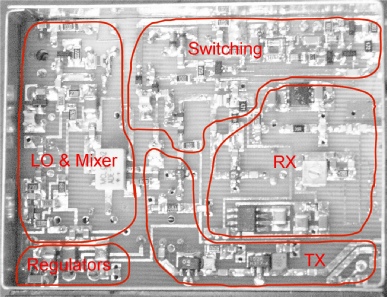
What I have always done with these kits is to do a progressive build. That is, start with the switching circuitry and voltage regulators, and then test that these areas are functioning. Then I do the LO and then finally the RX and TX strips ... testing each stage in turn. This is a good way to minimise the debug time if there is a fault. In this case there were three minor faults. The first was an inability to tune the LO onto 1152MHz ... or if it did, it wouldn't re-start. The clue in this case was the +8V rail was reading almost +9V and was caused by a discontinuity between the tab on the 7808 and the side-wall of the box (the centre pin is removed and the tab is soldered to the box). Once the joint was re-flowed, the oscillator behaved correctly. The second and third faults were both related to the TX strip. I could have connected the output up to my HP436A power meter (via a suitable attenuator) but I opted to just go with the detector output. However, there was no voltage showing on the detector output. A voltage check back through the TX strip showed 0V on the GALI-4. This turned out to be a component placement issue. I had placed the device slightly too far from the side-wall and the underside of pins 1 and 3 were shorting to the land that the tab was soldered to and effectively shorting out the supply to the MMIC. Because of the proliferation of through-plated holes it was a bit problematic lifting and re-sitting the MMIC ... once accomplished however, the voltmeter still showed no detector volts ... hmm? This I have to conclude was probably a solder whisker. A check across the schottky diode indicated an unwanted return to ground ... somewhere. Judicious use of fine solder-wick did the trick.
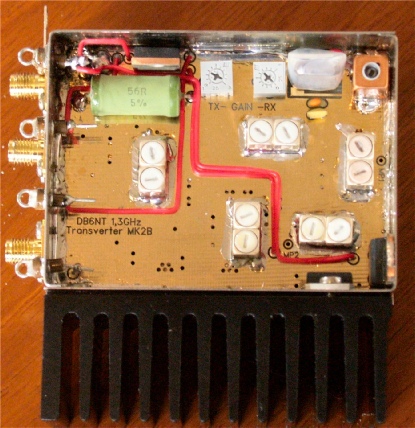
Note the one odd-size screw securing the solder-tag
As previously stated, these kits are NOT for beginners, in that they require the constructor to have previous knowledge and experience with SMD components. Another area of experience not touched on is rudimentary metal-work. Kuhne supply 12 M2 pan-head screws for securing the 3 SMA connectors to the box. However there are no nuts provided as you are expected to tap a 2mm thread in each of the 12 holes. This is simple if you have an M2 tap and a 1.6mm drill. Alternatively you can simply drill the holes M1.5 and use an M2 screw to cut the thread. If you can drill the holes less than M1.5 (but not too small), all the better, then use a tool like a braddle to enlarge the hole from the outside. This will increase the surface area for cutting the thread. The tin-plate box is only 0.6mm thick after all. If I have any criticism of this and similar kits it is only one and it is that the M2 screws provided are fine for securing the SMA connectors but are just that little bit too short to accommodate the solder-tag as well. To get around this minor nuisance, I simply drilled and tapped the appropriate hole to M2.5 and fitted an appropriate screw. I used M2.5 since the hole in the solder-tag was almost as large as the head of an M2 screw.
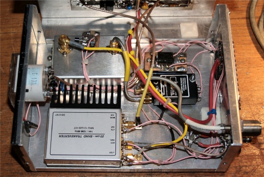
To quote the manual ‘ ... an additional LNA is not necessary.’ And I would probably agree if I didn’t live in Scotland where it has to be said, microwave activity is sparse compared to central Europe. With this in mind, I opted to leave the DEMI HEMT LNA in place when I swapped the transverter modules over. I found that the new transverter plus DEMI LNA with the 706MK2G pre-amp off gave a better gain/noise performance than without the LNA and with the 706 pre-amp on. With the current configuration, signals that were previously marginal at best and often non existent are now well clear of the noise.
Conclusion
The DB6NT MKU 13G2B 23cm transverter kit is a marvel in miniature technology. Michael has revised his original design in line with current technology trends to make available a kit which if assembled carefully will easily satisfy the most discerning microwave enthusiast.It is available from kuhne-electronic.
Price is currently €199.00 excluding shipping.
Specifications
Frequency Range RFFrequency Range IF
Output Power
RF Input Power
Noise Figure @ 18C
Receive Gain
Supply Voltage
Current Consumption
PTT Voltage (IF port)
PTT Voltage (PTT-connector)
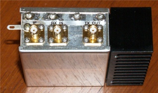
Coaxial Connectors
Case
Dimensions (excl. Heat-Sink)
...
1296 ...1298MHz144 ... 146MHz
min. 0.4W
max. 3W, adjustable
typ. 0.8dB
min. 20dB, adjustable
+12 ... +14V
typ. 350mA (TX)
+3V ... +14V
0V
SMA Female
Tinplate
55mm x 74mm x 30mm