RA17 L-C Filter problem solved!
8 minute read
August 2020
I have just spent the last three and a half weeks repairing a very sad looking RA117. Curiously it was masquerading as an RA117E, however it was definitely just a plain-vanilla 117 with 117E serial labels front and back ... very odd indeed.
It was in such a poor state that I opted NOT to even attempt powering it up until I was certain it wasn't going to go bang. So it wasn't until all the removable modules had been refurbished and re-aligned that we switched it on. And it worked! Sensitivity looked good, although there were several large spurius responses which I suspected might be eliminated once I had re-shaped all the filters. This, however was not to be so.
The 40MHz band-pass filter was a bit off, but I had seen worse, and the 37.5MHz filter was almost 'spot-on'. The IF bandwidths were a different story however. There was a definite unwanted HF response in the 1.2KHz filter and one of the trimmer capacitors was having no effect. This fault was easy to fix and was tracked down to a bad solder joint on one of the switch wafers in the L-C filter. However, although the correct response profile was achievable, the fact that two of the trimmer capacitors were either fully meshed or un-meshed, indicated that something was amiss.
So I tapped the module. As expected, the profile changed. Tapped it again ... more change. Actually, this is not an uncommon issue with RA17s etc. I believe this is the 4th time I have encounterd it in almost 50 refurbs, indicating a failure rate of almost 10%, which is not particularly good when you think about it.
There was a time when I had a small supply of spare filter modules, culled from scrap receivers. But like I said, this is a fualt that I am familiar with. Sometimes it can be resolved by tightening local earth connections, while other times it can be the result of a dry solder joint. And when all fails ... Simply replace the entire module!
This time however, there was no immediately apparent fault, and I was out of spare L-C modules. There was another curious symptom/effect evident too. Since I had been re-shaping the IF Bandwidths, the receiver was on its side. This is necessary to gain acces to V18 pin 7. Quite by chance I found that tipping the receiver as little as 10 degees back towards the horizontal resulted in a change in the filter response. Now what would cause that? I removed the L-C filter module from the 100KHz sub-chassis and instinctively shook it gently. It rattled ... not loud, but somethng was definitely loose.
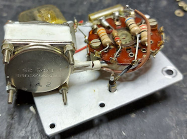
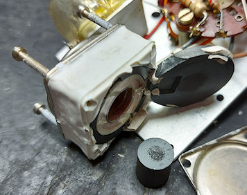
L-C Fiter removed from sub-chassis ... cover removed
2nd-top wafer assembly with Ferroxcube removed
Each Ferroxcube is attached to the sub-chassis using the extended case-screws which are 8BA size or equivalent. Care should be taken not to damage any of the very fine wires going to the switch wafer. The top Ferroxcube in the module is an inductor and thus only has two wires. All the others are transformers with a single secondary winding and a multi-tapped primary. A gentle shake of each 'cube' will identify the suspect.
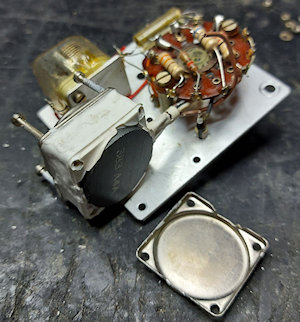
Outer cover removed
Now we need to remove one of the two outer covers by withdrawing the four extended screws. Since the device is 'potted' in rubber there will be resistance until the bond is broken. Only then will the screws come out. We need to remove the cover-plate which is adjacent to the emerging bundle of wires, as in the photograph on the left. This is simply prised off with a screwdriver.
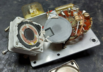
Ferrite cover removed
Using a fine blade or screwdriver, locate the edge of the ferrite cover where it makes contact with the ferrite cup and gently prise it off, being carefull not to damage each part or the fine wires. It should come away relatively easy as there is no adhiesive used other than the potting rubber.
Loose ferrite puck tipped out
As expected the central ferrite puck had become detached from the ferrite cup. As can be seen from the photograph on the left, this was held in place by a small drop of adhiesive. I applied a small blob of Superglue gel to the end of the puck, popped it back in and reassembled the Ferroxcube.
Further examination of the L-C Filter module identified a second Ferroxcube with detached ferrite puck. Once fully reassembled, the repaired module was re-integrated onto the 100KHz sub-chassis and re-aligned. Safe to say, tipping the receiver or tapping the module no longer results in any change to the filter response.
Flushed with success, I looked out a known faulty L-C module, and low and behold! Not one, but two loose ferrite pucks! I have to admit that I find it fascinating that given the relately close fit between the puck and the bobbin former that such small movement can result in such significant changes in filter response.
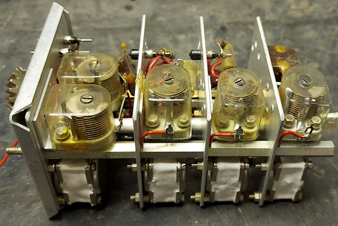
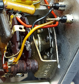
While on the subject of Filter Modules, there is another mechanical issue which manifests from time to time. During the production life of the RA17 series the detent system in the rotary switches changed. This generally affected both the L-C and the Crystal filters in the 100KHz IF strip and the System Switch. See the two photographs below.
Original style mechanism
Replacement style mechanism
The problem with the original 'leaf-spring' type is that over time the mechanism suffers wear. The result of this is that the ball-bearing fails to rotate and the inevitable occurs: It (the ball beraring) flies out and in the case of the L-C and Crystal Filters, it rattles around inside the module. If both modules used this type of mechanism and one failed, the user might not be aware that a bearing had come out. The only evidence might be that the Bandwidth Switch might have a lighter feel to it since the surviving detent mechanism is now serving both modules. I have seen this occur in several early RA17s.
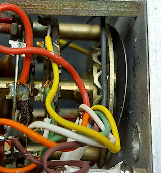
In the list of EMERs for the type (RA17 and RA17L), Mod Instruction number 15 would appear to address the issue. I say 'would appear', because the instruction refers to a switch designated SD, and there is NO SUCH switch in the RA17 or RA17L. However the description of the replacement switch matches the newer detent type where the bearing is securely retained. The instruction also correctly points out that the wafers in the replacement switch mechanism are NOT compatible with the older mechanism due to a 30 degrees difference in alignment. See the two photographs below.
Original style wafer
Replacement style wafer
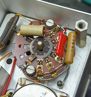
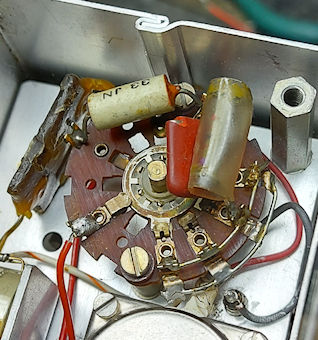
... And still on the subject of filters ... what about the spurious responses mentioned at the start of this article? Well, I discovered that someone had isolated and then completely by-passed the 2MHz - 3MHz band-pass filter. Essentially everything from DC to daylight was getting through from the 2nd mixer to the 3rd mixer.
Vandalised 2MHz-3MHz filter. Why on earth would someone do this?!
Mechanically, this filter is very similar to the Low-Pass Filter in the RA137. Consequentially it suffers from the same physical deterioration. All the plasic formers that retain the ferrites to the board had failed. The knock-on effect of this failure is that the ferrite cores are therefore no longer adjustable. This may have been why a previous owner had by-passed the filter ... after finding that attempts to 'tweak' the filter were fruitless. Just a theory.
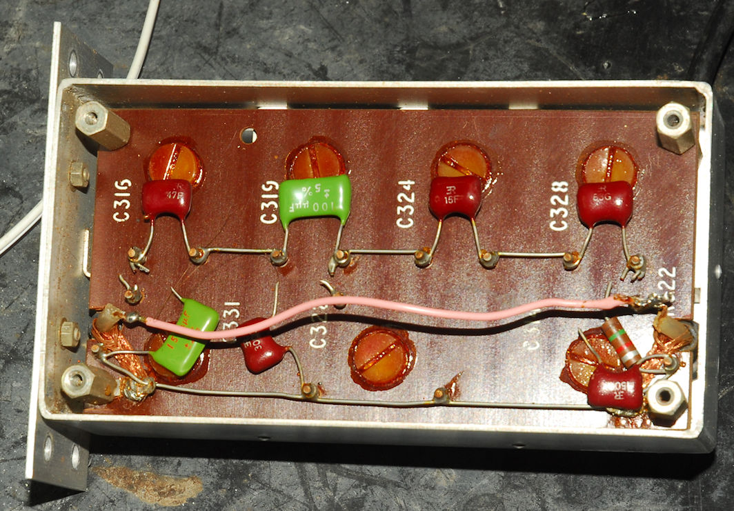
Raiding my junk-box, I found enough coil-formers to repair the filter and re-align it. The unwanted spurii are now gone! So good is the filter that the 37.5MHz breakthrough that L300 is intended to trap appears to be non-existent. The trick here is to disconnect the filter and replace it with a BNC-to-BNC lead, adjust L300 then re-fit the filter.
After over three weeks of work, the RA117 (serial number probably in the region of N1200) is now performing beautifully with a signal-to-signal plus noise ratio of between 23dB and 27dB for 1uV CW. Job done!