Refurbishing a Marconi CR100/1
8 minute read
This post is part of the series 'CR100':
- Refurbishing a Marconi CR100/2
- Refurbishing a Marconi CR100/1
October 2020
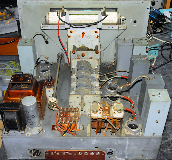
To be honest, I didn't expect to be refurbishing a second CR100 quite so soon. Unlike the CR100/2 that I worked on back in July, this one is a CR100/1. It is not as old, and internally it is in much better condition. It would appear to be free from any 'official' modifications, although there is a hole towards the top-left corner of the front-panel. The owner had removed all the valves and supplied these and all the screening cans in a seperate box. It even came with a bottom cover and original 5-pin power plug and socket! The only missing parts were the two scale-illumination bulbs.
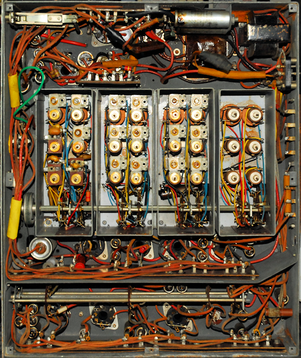
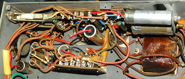
Removing the bottom cover revealed a clean underside and rubber-insulated wiring which at first-sight appeared in uncharacteristically good condition for its age. The steel screen over the detector/BFO tag-board had been removed. This was in the box all the valve cans. The green wire from the main switch to the the chassis is new but correct. Just under the mains transformer there are two wires which have been taped up using cloth electricians tape which tells me that this was likely done in the 60s or early 70s. These two wires had originally gone to the two (missing) mains decoupling capacitors. Something didn't look right between the two tag-boards where there was clear evidence that a couple of components had been moved or removed. Investigation proved that all the wiring and components were in the 'correct' place, so I have to conclude that maybe someone had been experimenting and then put everything back but not as neatly, using PVC insulation to insulate an off-board joint. Both of the two horizontally-mounted capacitors definitely showed signs of heating and were leaking a nasty sticky brown substance.
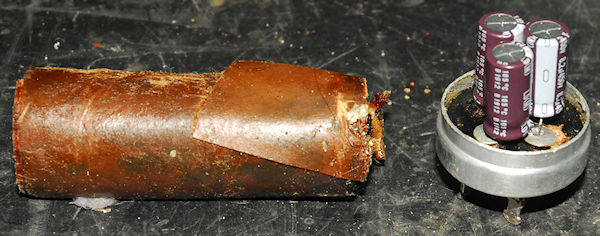
But first ... Ensure it doesn't go bang when switched on!! For this, I carried out the mandatory re-stuffing of the power-supply smoothing pack, which in the CR100 consists of three 8uF capacitors.
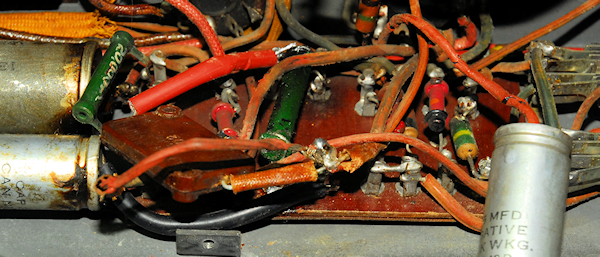
Above and below: First impressions are that this area has been modified ... which is not the case. Yes, C96 has been removed at some point then put back, with one lead extended; probably to make it easier to re-attach. The value of C96 was measured and found to be significantly lower than specified so it was replaced with a modern capacitor. All nine of the metal-can stud-mounted capacitors in this area were re-stuffed and all the carbon resistors were replaced with 1W carbon or metal-film types. I also replaced the Audio Gain control since I found that the wire-wound track was damaged.
With this 'second' CR100, I was hoping to clear up the puzzle surrounding the large bundle of severed wires that I had encountered when refurbishing the CR100/2 back in July. However, I didn't find any 'un-cut' wires in this one. There is, as expected a few wires relating the phones jacks and a couple carrying the signal from the final IF-stage but nothing like the mass of coaxes that I found in the CR100/2. So the jury is still out on that one.

All the carbon resistors have been replaced, including R7 (22K 3W), which is in its revised position as mentioned on page 14 of the manual. A further 20 stud-mounted capacitors have also been re-stuffed. As said, the wiring in this particular CR100 is largely in good condition. The exception being those wires covered in blue or black insulation, all of which has gone brittle and is disintegrating. Thus every blue and black wire has been replaced. I also replaced all the wires leading from the coil-box before refitting it.
Left: As with the CR100/2, there was considerable 'pointer-lag'. This was eliminated using the same simple fix using a piece of looped steel wire and a cable-tie.
Note how the celuloid vernier discs in this CR100/1 are in very good condition ... which, incidentally is more than I can say for the front panel which has been 'abused'. A previous owner, clearly a fan of Post-WW2 BBC broadcasts, had scratched 'Home', 'Light' and 'Third' into the paint surrounding the tuning bezel. No wonder I couldn't clean it off!!
When testing the valves, four were found to be faulty. One half of the U50 heater was dim. This was replaced with a new 5Y3GT. Three of the VR100s had broken wires inside the bases ... two replaced with used but good KTW61s and a 6K7 was used for the VFO (see below).
Page 9 in the CR100 manual lists the valves used and gives Service Types and 'possible Substitutes'. For the RF and IF stages and the VFO (Frequency-change Oscillator as it is called), the preferred type is a KTW62 or VR100. 'Possible Substitutes' are KTW61, NR64, 6K7G and 6J7G. I found the inclusion of the 6K7G here unusual since I have always seen the 6K7G as a direct replacement for the lower gain KTW63. The suggestion that the 6J7G was also suitable was an even bigger surprise given that its gain is even lower than that of the 6K7G and the maximum Anode current is a paltry 2mA. Having exhausted my supply of KTW61s and 62s, I opted to try a 6J7G in V4 (VFO) position. It worked, but with a noticeable drop-off in performance at the higher frequencies. I then replaced it with a new (old stock) 6K7G, which to my surprise, worked perfectly. I put this valve and my other NOS 6K7G on my VCM-163 and found that both performed as well as a KTW62. In fact the parameters measured were almost identical. I have always avoided using KTW63s as a substitute for VR100s. Unfortunately I don't have any KTW63s to compare against, but I have to wonder if some 6K7Gs might perform better than others under certain conditions. I note that they do tend to exhibit higher gain as the Anode voltage increases ... and the HT+ line on the CR100 is a lot higher than that in the R1155 ... but that doesn't explain the test results on my VCM-163.
Alignment was perfectly straight-forward with no issues encountered. I even managed to iron out the problem with the narrow bandwidths that I had with the CR100/2 back in July. With V4 removed, I injected the output from my VNWA at Grid (top-cap) of V3 and connected the input of the VNWA to pin 4 of V8. The metal screen around the base of V4 needs to be off to gain access. With the VNWA sweeping between 460KHz and 470KHz I was able to align all the IF stages as per the manual. The 100Hz bandwidth is achieved in the audio stage but IF1 and IF2 need to be carefully adjusted to achieve the 300Hz bandwidth. The way to achieve this is to first align the 1200Hz bandwidth then switch to 300Hz. If IF1 or IF2 are not set correctly there is likely to be little difference between the 1200Hz and 300Hz positions. It is necessary to switch back and forth between 1200Hz and 300Hz, adjusting IF1 and IF2 each time until the correct filter profile is achieved.
An intermittent loss of audio output had me scratching my head. After cleaning every switch contact in sight with De-Oxit the audio was still dropping out. Then I remembered that the loudspeaker feed was routed through the two front-panel headphone jacks ... duh! A squirt of De-Oxit and a correct size plug inserted several times cleared the problem.
I have heard varying descriptions of the performance of the CR100. It sounds like you either love it or hate it. Portishead Radio used them right up until the 60s, when they were given the Racal RA1217, which was NOT a popular move. Others say that the CR100 drifts like an express train. Well, I've now refurbished two versions of the type and can say that it does not drift as described. The two RF stages prior to the mixer give it very good sensitivity, although performance does drop off slightly above 14MHz. It is also superb on the LF bands right down to 60KHz. It may be an ugly cube and lack the finesse of the RA17 etc., but it was designed in 1940 and it certainly does what it was designed to do.
The CR100/1, as received ... note the hole in the front-panel
Removing the bottom cover revealed a clean underside and rubber-insulated wiring which at first-sight appeared in uncharacteristically good condition for its age. The steel screen over the detector/BFO tag-board had been removed. This was in the box all the valve cans. The green wire from the main switch to the the chassis is new but correct. Just under the mains transformer there are two wires which have been taped up using cloth electricians tape which tells me that this was likely done in the 60s or early 70s. These two wires had originally gone to the two (missing) mains decoupling capacitors. Something didn't look right between the two tag-boards where there was clear evidence that a couple of components had been moved or removed. Investigation proved that all the wiring and components were in the 'correct' place, so I have to conclude that maybe someone had been experimenting and then put everything back but not as neatly, using PVC insulation to insulate an off-board joint. Both of the two horizontally-mounted capacitors definitely showed signs of heating and were leaking a nasty sticky brown substance.
The CR100/1 underside, as received.
But first ... Ensure it doesn't go bang when switched on!! For this, I carried out the mandatory re-stuffing of the power-supply smoothing pack, which in the CR100 consists of three 8uF capacitors.
Above: The old and the new.
C96 has definitely been off the board.
Above and below: First impressions are that this area has been modified ... which is not the case. Yes, C96 has been removed at some point then put back, with one lead extended; probably to make it easier to re-attach. The value of C96 was measured and found to be significantly lower than specified so it was replaced with a modern capacitor. All nine of the metal-can stud-mounted capacitors in this area were re-stuffed and all the carbon resistors were replaced with 1W carbon or metal-film types. I also replaced the Audio Gain control since I found that the wire-wound track was damaged.
Detector, BFO and Audio circuits finished.
With this 'second' CR100, I was hoping to clear up the puzzle surrounding the large bundle of severed wires that I had encountered when refurbishing the CR100/2 back in July. However, I didn't find any 'un-cut' wires in this one. There is, as expected a few wires relating the phones jacks and a couple carrying the signal from the final IF-stage but nothing like the mass of coaxes that I found in the CR100/2. So the jury is still out on that one.
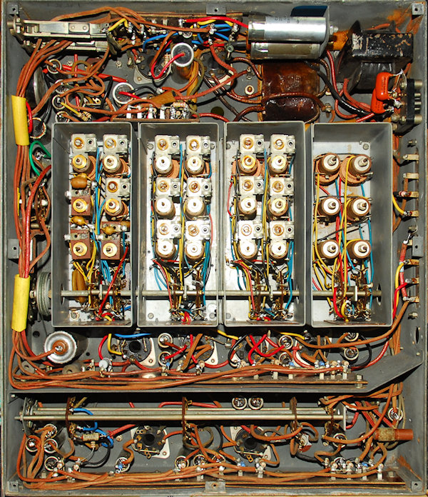
CR100/1 underside, coil-box removed.
All the carbon resistors have been replaced, including R7 (22K 3W), which is in its revised position as mentioned on page 14 of the manual. A further 20 stud-mounted capacitors have also been re-stuffed. As said, the wiring in this particular CR100 is largely in good condition. The exception being those wires covered in blue or black insulation, all of which has gone brittle and is disintegrating. Thus every blue and black wire has been replaced. I also replaced all the wires leading from the coil-box before refitting it.
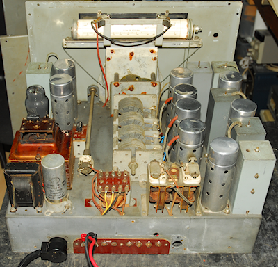
The CR100-1 underside. All done!
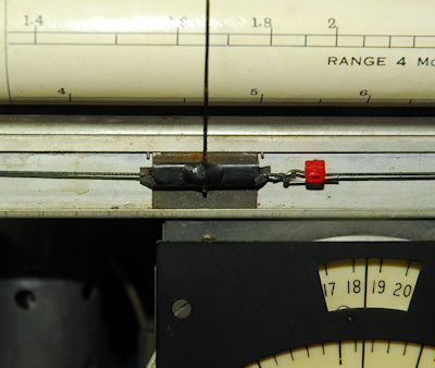
Pointer lag eliminated.
Left: As with the CR100/2, there was considerable 'pointer-lag'. This was eliminated using the same simple fix using a piece of looped steel wire and a cable-tie.
Note how the celuloid vernier discs in this CR100/1 are in very good condition ... which, incidentally is more than I can say for the front panel which has been 'abused'. A previous owner, clearly a fan of Post-WW2 BBC broadcasts, had scratched 'Home', 'Light' and 'Third' into the paint surrounding the tuning bezel. No wonder I couldn't clean it off!!
When testing the valves, four were found to be faulty. One half of the U50 heater was dim. This was replaced with a new 5Y3GT. Three of the VR100s had broken wires inside the bases ... two replaced with used but good KTW61s and a 6K7 was used for the VFO (see below).
Page 9 in the CR100 manual lists the valves used and gives Service Types and 'possible Substitutes'. For the RF and IF stages and the VFO (Frequency-change Oscillator as it is called), the preferred type is a KTW62 or VR100. 'Possible Substitutes' are KTW61, NR64, 6K7G and 6J7G. I found the inclusion of the 6K7G here unusual since I have always seen the 6K7G as a direct replacement for the lower gain KTW63. The suggestion that the 6J7G was also suitable was an even bigger surprise given that its gain is even lower than that of the 6K7G and the maximum Anode current is a paltry 2mA. Having exhausted my supply of KTW61s and 62s, I opted to try a 6J7G in V4 (VFO) position. It worked, but with a noticeable drop-off in performance at the higher frequencies. I then replaced it with a new (old stock) 6K7G, which to my surprise, worked perfectly. I put this valve and my other NOS 6K7G on my VCM-163 and found that both performed as well as a KTW62. In fact the parameters measured were almost identical. I have always avoided using KTW63s as a substitute for VR100s. Unfortunately I don't have any KTW63s to compare against, but I have to wonder if some 6K7Gs might perform better than others under certain conditions. I note that they do tend to exhibit higher gain as the Anode voltage increases ... and the HT+ line on the CR100 is a lot higher than that in the R1155 ... but that doesn't explain the test results on my VCM-163.
Finished! ... sorry, I forgot to photograph the front.
Alignment was perfectly straight-forward with no issues encountered. I even managed to iron out the problem with the narrow bandwidths that I had with the CR100/2 back in July. With V4 removed, I injected the output from my VNWA at Grid (top-cap) of V3 and connected the input of the VNWA to pin 4 of V8. The metal screen around the base of V4 needs to be off to gain access. With the VNWA sweeping between 460KHz and 470KHz I was able to align all the IF stages as per the manual. The 100Hz bandwidth is achieved in the audio stage but IF1 and IF2 need to be carefully adjusted to achieve the 300Hz bandwidth. The way to achieve this is to first align the 1200Hz bandwidth then switch to 300Hz. If IF1 or IF2 are not set correctly there is likely to be little difference between the 1200Hz and 300Hz positions. It is necessary to switch back and forth between 1200Hz and 300Hz, adjusting IF1 and IF2 each time until the correct filter profile is achieved.
An intermittent loss of audio output had me scratching my head. After cleaning every switch contact in sight with De-Oxit the audio was still dropping out. Then I remembered that the loudspeaker feed was routed through the two front-panel headphone jacks ... duh! A squirt of De-Oxit and a correct size plug inserted several times cleared the problem.
I have heard varying descriptions of the performance of the CR100. It sounds like you either love it or hate it. Portishead Radio used them right up until the 60s, when they were given the Racal RA1217, which was NOT a popular move. Others say that the CR100 drifts like an express train. Well, I've now refurbished two versions of the type and can say that it does not drift as described. The two RF stages prior to the mixer give it very good sensitivity, although performance does drop off slightly above 14MHz. It is also superb on the LF bands right down to 60KHz. It may be an ugly cube and lack the finesse of the RA17 etc., but it was designed in 1940 and it certainly does what it was designed to do.