Is your RA17 a MKI or MKII?
7 minute read
February 2013
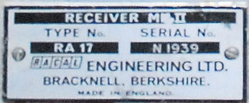
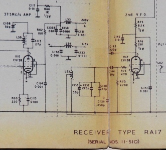
The question, ‘What defines an RA17 MK2 from a MK1?’ is a common one and anyone could be forgiven for thinking that there must be precise delineating features. However, the more I look into the issue, the more muddy the waters become. BUT, before I go any further and it is pointed out by someone else, some RA17 MK2s do actually state MK2 on the serial number plate as in the photograph on the right. There is even a school of thought that marks the boundary between RA17 and RA17 MK2 thus: ‘those with serial numbers 511 and above are MK2s’. This premise is probably based on the annotation at the bottom of the circuit diagram in early RA17 manuals ... See the below.
But that argument doesn’t hold much water either. A few years ago I was given the remains of RA17 Ser. N573. It was missing the 1st-VFO module and the Calibrator. Through time I obtained replacements for these and eventually proceeded to rebuild the receiver, and it didn’t take me long to realise that something was different about the power supply. There was no 9K ‘stand-by’ resistor, yet there was a ‘STAND BY’ position on the front panel switch. What was perplexing was the fact that although the switch had 5 positions, there were only 5 solder-tags per wafer. This implied, and I verified the fact, that when the switch was in the ‘stand by’ position the wiper was in effect ‘pointing’ to itself! See the images below. I don’t have a photograph of N573’s PSU but the photograph on the left is of an even earlier RA17 (N54). N558's PSU is identical. Note the missing resistor. Then compare it with the photograph next to it of an other early RA17, this time with the 9K resistor.
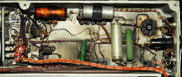
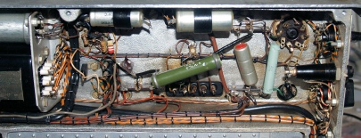
Thus, you would think that here is clear evidence of where a MK2 differs from what we will call a MK1. But you would be wrong because the photograph on the right is in fact from RA17 N558 and obviously pre-dates N573. Confused?
Another area for consideration is the input attenuator … or rather, the addition of a Low-Pass Filter ‘in front’ of the attenuator. To date, I can only find documented evidence of this filter when referring to manuals relating to the RA17L. But see the photographs below. Note the physical differences in the actual switch mechanisms; the lack of the rear mounting plate on the earlier attenuator and the fact that N1939, being a MKII (as its serial plate states) has the additional LP filter ... and in order to 'take' the rear mounting plate, N1939's chassis has the appropriate holes. So we can't use the Attenuator determine which mark.
Another area for consideration is the input attenuator … or rather, the addition of a Low-Pass Filter ‘in front’ of the attenuator. To date, I can only find documented evidence of this filter when referring to manuals relating to the RA17L. But see the photographs below. Note the physical differences in the actual switch mechanisms; the lack of the rear mounting plate on the earlier attenuator and the fact that N1939, being a MKII (as its serial plate states) has the additional LP filter ... and in order to 'take' the rear mounting plate, N1939's chassis has the appropriate holes. So we can't use the Attenuator determine which mark.
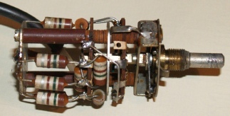
Input attenuator RA17 N664
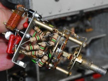
Input attenuator RA17MKII N1939
What about the Calibrator? Forget the fact that in some Calibrators R84 is1M, whilst in others you might find a 22K resistor. To quote Rob Filby … This calibrator modification was undertaken by GCHQ and is known as departmental modification A. A Red modification label with letters instead of numbers is stuck on the back of the sets.
There is another difference to look for. In this case, how it is mounted. In the MKII and 17L, the end of the Calibrator furthest from the 2nd VFO is secured to a paxolin block by way of an L-bracket. In the ‘plain-vanilla’ RA17, there is no L-bracket. Instead there is a cylindrical paxolin spacer screwed to the underside of the Calibrator. This spacer is not physically attached to the 1st VFO.
There is another difference to look for. In this case, how it is mounted. In the MKII and 17L, the end of the Calibrator furthest from the 2nd VFO is secured to a paxolin block by way of an L-bracket. In the ‘plain-vanilla’ RA17, there is no L-bracket. Instead there is a cylindrical paxolin spacer screwed to the underside of the Calibrator. This spacer is not physically attached to the 1st VFO.
Calibrator RA17 N558
Note: The spacer is hidden behind the EF91 on the 1st VFO
Note: The spacer is hidden behind the EF91 on the 1st VFO
Calibrator RA17MKII N1939 with L-bracket
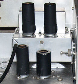
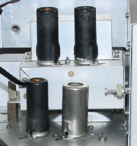
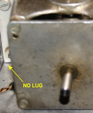
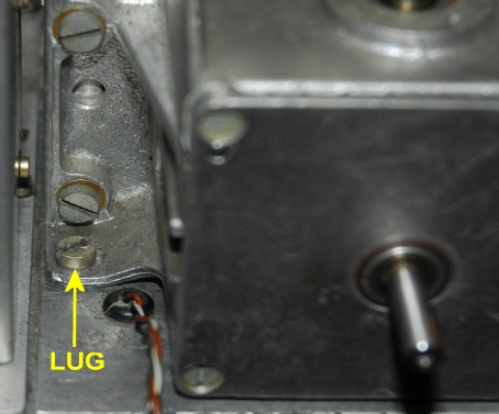
As far as the 1st VFO is concerned, and as far as I can discern, there is no difference, mechanical or electrical. However, when it comes to the 2nd VFO there is one significant mechanical difference. Anyone who has dismantled an RA17 will testify to the fact that in order to gain access to one of the 2nd VFO retaining screws it is first necessary to remove the VFO cover which itself is secured by no less than 15 short 6BA screws! The 2nd VFO in the RA17L is secured to the chassis by three 2BA screws and to date this has also been the case in all the MKII RA17s that I have come across. Look at the photographs below. The one on the left is from RA17 N664. The one on the right is from RA17 MKII N2701. Thus if the Serial plate just says RA17 and the 2nd VFO has the third mounting screw, then there is a chance that it is a MKII ... but you would have to confirm that someone had not substituted a MKIII (17L) 2nd VFO (there are electrical differences).
There are other variations in the mechanical aspects of the 2nd VFO. Some people may have come across some units where there is a small square panel attached tot he LH side of the unit. This is an officially sanctioned modification to improve the linearity of the tuning mid-scale. All this does is ‘move’ the side wall of the VFO a millimetre further away from the main tuning capacitor. The film-strip carrier also went through a few evolutions during the production life of the receiver.
Regarding the 1MHz Oscillator, Harmonic Generator, Harmonic Mixer, 37.5MHz Amplifiers and the 2nd Mixer … there is no difference that I can tell. I will go as far as saying that this might even apply to all subsequent variants … with the exception of the RA17C12 and the RA117, both of which used North American valves (tubes).
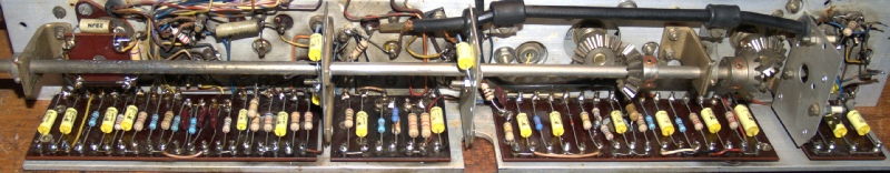
Moving on though, … its in the 3rd IF, the 100KHz strip, that we find some very interesting differences …
Regarding the 1MHz Oscillator, Harmonic Generator, Harmonic Mixer, 37.5MHz Amplifiers and the 2nd Mixer … there is no difference that I can tell. I will go as far as saying that this might even apply to all subsequent variants … with the exception of the RA17C12 and the RA117, both of which used North American valves (tubes).
Moving on though, … its in the 3rd IF, the 100KHz strip, that we find some very interesting differences …
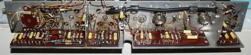 100KHz IF-Strip (minus the selector shaft) in RA17 N558.
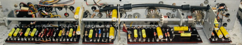 100KHz IF-Strip in RA17MKII N1939
 For comparison … 100KHz IF-Strip in RA17W Ser. 9031
Looking at the photographs above, it is relatively easy to spot the differences. Throughout the life of the RA17 series (RA117 incl.), there has been no difference in the circuitry associated with the two 100KHz outputs. Similarly the circuitry on the small tag-board in the middle remained largely unchanged, except R194 and C117 are swapped over in the MKII and the 17L. In the RA17L etc. and RA117 this is where the AVC clamp-diode V24 was attached to the divider. (See note below). The circuitry on the front tag-board (on left) also remained largely unchanged, however in early RA17s, as can be seen, various components were mounted at 90 degrees. It does look like it is fair to say that the RA17MKII shares the same component orientation on this board as the RA17L. On the third tag-board, in both RA17 and RA17MKII, three components (C159, R81 and C195) are mounted at 90 degrees. From the RA17L onwards, this tag-board changed considerably due to the fact that the AVC is applied to the 3rd IF and the RF amplifier.
Note: I have read somewhere that the AVC clamp-diode in early RA17Ls was originally a semiconductor on the third tag-board. It wasn’t until later that the EA76 thermionic diode was fitted instead. Repair instructions for replacing a failed EA76 with a semiconductor instruct you to fit the diode more or less in place of the EA76. HOWEVER, I have found that the third tag-board is actually still wired for the semiconductor AVC diode. Hence, in the bottom photograph above you may be able to make out a tiny 1N916 (fitted as a repair) just to the right of one of the yellow capacitors.
Note: I have read somewhere that the AVC clamp-diode in early RA17Ls was originally a semiconductor on the third tag-board. It wasn’t until later that the EA76 thermionic diode was fitted instead. Repair instructions for replacing a failed EA76 with a semiconductor instruct you to fit the diode more or less in place of the EA76. HOWEVER, I have found that the third tag-board is actually still wired for the semiconductor AVC diode. Hence, in the bottom photograph above you may be able to make out a tiny 1N916 (fitted as a repair) just to the right of one of the yellow capacitors.