RA117A N0959
29 minute read
February 2024
Over the years, I have refurbished a couple of RA117s and two RA117Es. I've even had the honour of taking apart and re-building what was clearly a very early, dare I say prototype RA117. Recently, I had the opportunity to carry out a full refurb on my first RA117A ... at least that is what is stamped on the serial plate.
First of all, the RA117 was never a successor to the RA17. Rather, is was conceived in order to allow for greater variety of auxiliary equipment and control. Where as there are something like 40 definable variations of RA17s etc. where the greyest area appears to be the difference between a MK1 and a MK2. As far as I can ascertain, there are only about a dozen variations of the RA117, with the 117, 117A and 117E being the most prevalent. All the rest appear to be 'specials' or made for export. So, focusing on the three 'popular' variations of RA117, you would think that the differences between the 117, the 117A and the 117E would be clear ... right? Not quite!
OK, the RA117E, originally specifically made for the Royal Navy, as part of a configuration known as CJK, is unique in that it has a single silicon transistor in its modified AGC system. So that feature alone identifies the RA117E. The RA117 manual (or at least the one in my possession) includes an RA117E appendix which states that the 117E is a modified 117, and it goes on to give details of these modifications. However, as I said, I have refurbished two RA117Es. Both were modified exactly as per the afore mentioned appendix, but one had a 2nd VFO circuit which matched that detailed in the schematic for the RA117A, that is, it included the big chunky 3W 150V Zener diode and associated resistors in the anode circuit of V12B. My current RA117E does NOT have the Zener-stabilised VFO. There's nothing like a bit of inconsistency to keep you on your toes! Carefully comparing the RA117 and RA117A schematics that I can find, there are only three differences. The most obvious being the Zener diode etc. added to the 2nd VFO. The others relate to the AGC clamp-diode and the headphone jacks. The RA117A schematic shows the clamp-diode as a 1N916, replacing the thermionic EA76 found in the RA17 and RA17L etc., but the function is identical ... and since the EA76 was ultimately considered obsolete, replacing it with a 1N916 was an authorised repair. The AVC tag-board in the 100KHz IF module is even pre-wired for the 1N916! The RA117A schematic also shows a 4R7 resistor in series with the internal loudspeaker. This resistor does not feature in the RA117, apparently.
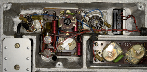
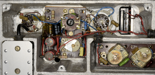
Interestingly, the RA117A that I was entrusted with did NOT comply with the schematic. In fact, internally it appears to be a plain vanilla RA117. There is no Zener in the 2nd VFO, the clamp-diode is a good old EA76 and there is no 4R7 resistor in series with the loudspeaker. This RA117A is identical to my own RA117. So, what is the defining difference between an RA117 and an RA117A? After much trawling of the internet, I have come to the conclusion that the distinction between the 117 and 117A is similar to that separating the RA17 and RA17 MK2. Not a lot, really ... maybe. The only direct reference to the RA117A that I have been able to find, is on Keith's Vintage Racal Site where there is reference to an RA117A-1, described as an 'RA117A modified with American plugs and valves'. As far as I am aware ALL production RA117s used North American valves and connectors. The only RA117 that I have encountered which didn't follow this convention was the one which I believe to be a prototype. That one retained all the valves used in the RA17L, except in the 2nd VFO and 3rd & 4th Mixer module, where the latter is also significantly different in circuit design and orientation ... see the photographs below.
Typical RA117 3rd & 4th Mixer
3rd & 4th Mixer on 'prototype RA117'
I would go as far as to say that what we have in the RA117A is actually a fully-fledged RA117... where the 'A' is a metaphorical 'rubber stamp' to say that the design and build standard for the type is finally signed off ... no more incremental changes.
But this RA117A does have some interesting extras at the back. See the photographs below.
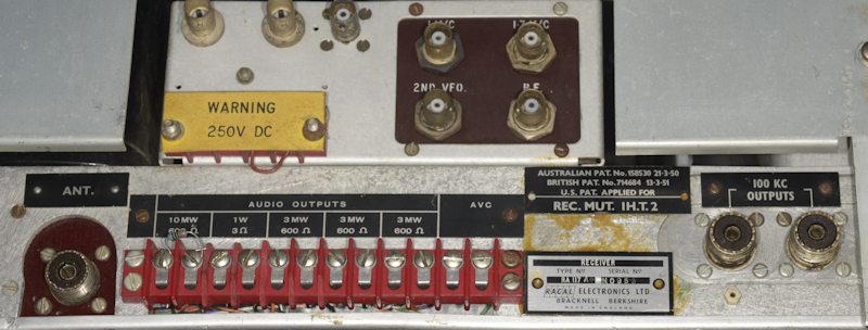
RA117A N0959 Rear
Extra connectors at rear
As can be seen, there are three additional anonymous BNC connectors mounted on the rear panel. The two round ones are not even connected to anything in the receiver. Instead they simply facilitate a 4K7 resistor in series with a 100nF capacitor. The third BNC connector has about 10cm of coax which is terminated in a BNC plug with no immediately obvious purpose.
Given what we have already found, it would be easy to say that this is nothing more than a modified plain vanilla RA117. However, as is obvious, those responsible took the trouble to glue the Patent and Serial plates onto the rear of the main chassis. The original mounting holes on the sub chassis match the holes in the two plates. Obviously it was important to re-affix both plates. So for the moment I am prepared to accept that this is indeed an RA117A, even if it doesn't conform to the schematic.
This receiver belongs to a good friend and returning client and I also happen to know that he got it from a mutual acquaintance who I trust to have NOT stored it in a damp shed, even though such a habit does appear to be quintessentially British. I say this because when I came to remove the right gusset panel ... I couldn't!
All production RA117s used American UNC screws. I think the side panels are held on with 10-24 UNC screws, the closest equivalent to 2BA. The two at the rear were completely seized. I had to resort to drilling the heads off to remove the panel. Between the chassis and the panel there was a fearful amount of rock-hard aluminium oxide deposit. As I don't have any UNC taps, I drilled each screw out and re-tapped the holes to M5. The left side gusset panel came off without difficulty. The 1st and 2nd VFOs were easily removed, as was the 3rd & 4th Mixer module. Obviously the front panel needs to come off too.
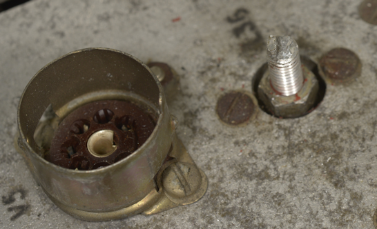
Given the location of the corrosion it seemed very likely that this receiver had been stored on its (right) side, in a less than dry environment for some time. The likelihood of this being the case was more or less confirmed when I came to work on the PSU/Audio compartment and found that the 4-40 UNC screws in the valve sockets were seized, as were at least one of the screws securing the mains transformer and one securing a P-clip ... the heads of both of which sheered off. The screw for the transformer was drilled out and re-tapped M5 and the screw for the P-clip was replaced with a 4BA screw and nut. All these screws would have been in close proximity to the ground if this receiver were stored on its sight side. I rest my case!
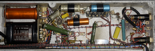
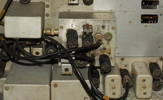
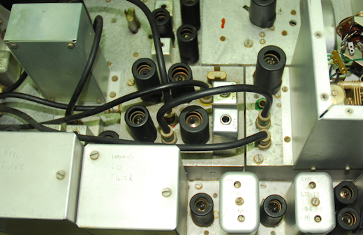
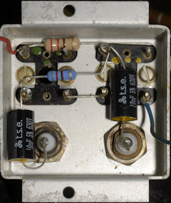
PSU/Audio compartment before
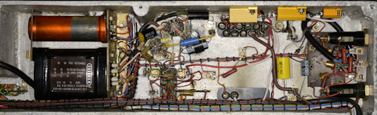
PSU/Audio compartment after
In the PSU/Audio compartment, all three of the vitreous-enamel wire-wound resistors were replaced by suitable metal-clad types ... something that was a routine Racal-sanctioned mod, covered by an EMER. The 2 x 32uF smoothing pack was cut open and re-stuffed with two modern aluminium electrolytic capacitors. The remaining tubular paper capacitors were replaced with modern polypropylene ones and all carbon-composite resistors were replaced with modern carbon-film types. The RA117 comes with a 'wired' mains cord and no external means of selecting the mains voltage, thus the appropriate taps on the transformer have to be individually selected. Curiously, Racal chose NOT to include a suitable annotated diagram showing which terminals are which. Fortunately it is not difficult, with the aid of a multimeter, to work them out. See below.
RA117 Mains Transformer
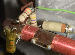
After the PSU/Audio compartment, I always move on to the 1st VFO module. In the RA117, this is identical to that in the RA17L, with one exception ... there is no 500KHz - 1MHz range in the preselector. This has been replaced with a Wideband setting terminated in 75-ohms. A possible reason for omitting this range might be because the RA117 can be 'married' to an MA79 and the latter has a lower frequency limit of 1.5MHz.
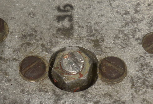
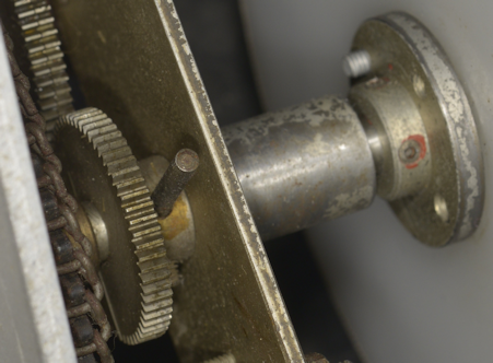
Straight away I noticed a couple of issues with the 1st VFO module. The tuning screw for L36, which sets the low end of the VFO, was fully retracted and damaged. Also, the pin which forms part of the mechanical end-stop for C76 had been deliberately bent 90 degrees so that it no longer made contact with the end-stop screw. See below.
Fully retracted and damaged L36 screw
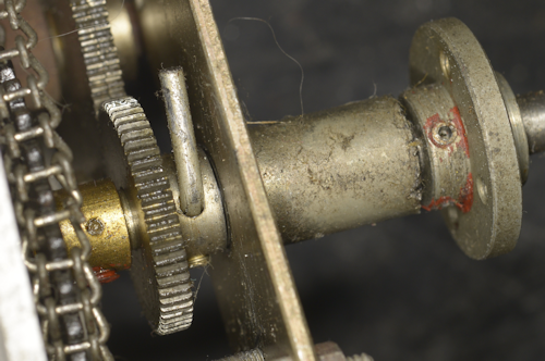
Damaged mechanical end-stop
It was obvious that the two were connected; The VFO upper and lower limits of the VFO had likely proven impossible to set without setting the inductance of L36 to a minimum. From past experience, I already knew what the issue was ... trimmer C77 was very likely full of dirt and therefore a much higher capacitance than it should be. This turned out be the case and easily removed, cleaned and replaced. But what to do with the bent end-stop pin? Being of soft steel, straightening it out was easy, but not unexpectedly, it cracked. Also, knocking it out was not an option ... again because it was made of a soft metal. And, extracting the gear through which it was inserted was not an option on account of the way the entire mechanism was constructed. It would prove easier to replace the entire 'gearbox' with one salvaged from a scrap module. It is a good thing that I have a large supply of spare, and thus sacrificeable parts; This being the second gear mechanism to require replacing in a month. The previous being a MK2 RA17 where the large Meccano gear was not secure on its collar, resulting in a momentary lag when the MHz knob was turned.
Inside of the 1st VFO module before
Despite looking pristine inside, most of the resistors were right on the upper tolerance limit, and all the tubular paper capacitors were at least 100% high in value.
Inside of the 1st VFO module with the Rs & Cs replaced
During re-test, no issues were encountered re-aligning the preslector and testing the pre-amp. As expected, with C77 now free of dirt and verified working, the VFO tracking was was set up without issue. Incidentally, this operation used to be a tricky procedure, as connecting a probe of any sort to TP2 has a pulling effect on the oscillator. However, last year I treated myself to a TinySA Ultra. This little box of wonder has proven itself to be very useful in this case. I simply connect its little telescopic aerial and set it to sweep from 30MHz to 80MHz ... no pre-amplification required. The VFO frequency is easily picked up and the peak is automatically measured and displayed on the screen ... Dead Easy!
L36 screw now set as it should be
New mechanical end-stop
Since the end of L36's aluminium shaft had been damaged, I carefully filed the slot slightly deeper. Fortunately there was no need to screw it in further than the lock-nut. The end-stop on C76 was set such that it didn't quite hit its built-in end-stop. I did manage to transfer over the bush for the Delrin MHz disc. This was considered important since it meant that the same 4-40 UNC counter-sunk screws could be used ... purely an aesthetic thing.
Whereas VFO1 in the RA117 is more or less identical to that in the RA17 etc., the same cannot be said for VFO2. As mentioned before, the reason for creating the RA117 was to have a receiver with all the qualities of the RA17, but with greater scope for external auxiliary equipment. Part of this involved the insertion of another level of conversion ... taking it from double conversion to triple-conversion. See the block diagram below. This resulted in two necessary changes to the 2nd VFO. Firstly, the LO frequency is raised from 2.1MHz - 3.1MHz up to 3.6MHz - 4.6MHz. This was necessary in order to facilitate a new 3rd IF at 1.6MHz. And to do that, a new module, encompassing the 3rd and 4th mixers, a buffer stage and a 1.7MHz crystal oscillator was required. In order to accommodate the new 3rd & 4th Mixer module such that it and the 2nd VFO fitted within the original footprint of the RA17 2nd VFO, the 2nd VFO needed to be significantly smaller.
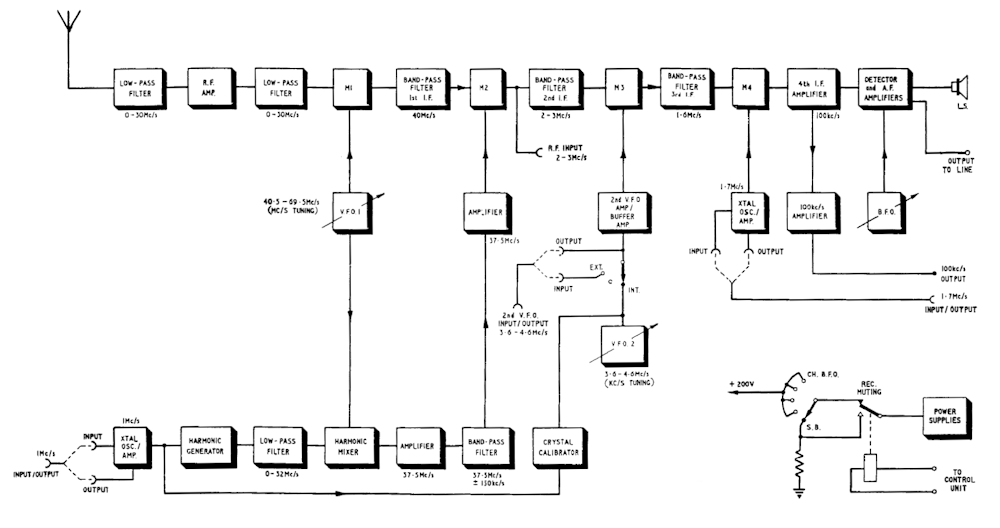
Block Diagram of RA117
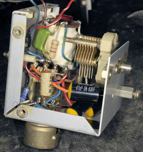
At first sight, the 2nd VFO module in the RA117 looks somewhat similar to that in the MA79 Drive Unit ... to which the RA117 can be 'married' to. However, electrically the two are far from similar. Neither is the RA117s 2nd VFO circuit similar to that in the RA17. The KHz VFO in the MA79 is an ovenized Pentode-based Colpitts oscillator. The 2nd VFO in the RA17 is a very stable Pentode-based Hartley oscillator. The 2nd VFO in the RA117 is also a Hartley oscillator, but unlike the RA17, it is based around a Triode, one half of V12. The frequency stability of the 2nd VFO in the RA117 is significantly poorer than the RA17. This might not have been considered an issue since the RA117 was intended to be operated with an external 2nd VFO, like the MA350B Decade Frequency Generator. In order to reduce the size of the VFO, the tuneable band-pass filter was omitted and a fixed Band-Pass filter was added as a stand-alone fixture.
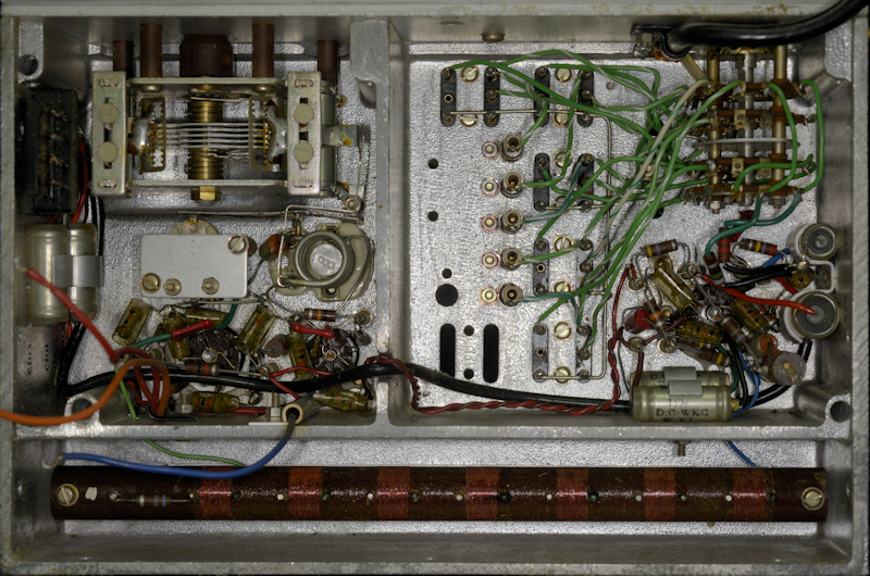
Inside of 2nd VFO, before
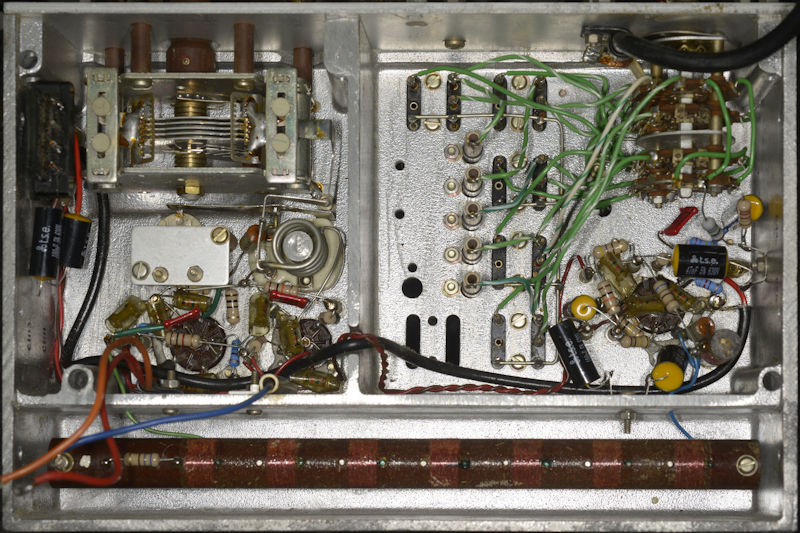
Inside of 2nd VFO, after, spot the extra wires!
No issues with this module, other than the extra wires discovered on the wafer-switch. Their purpose is a mystery as they completely render the VFO switch inoperative. I have to admit that I only discovered this wiring issue during test when I realised that the VFO switch was in the EXT position and the VFO was still running. The blue wire and tcw (tinned copper wire) link have now been removed.
On the subject of replacing components ... Generally the components found in RA117s appear in good condition, largely due to the fact that all RA117s were manufactured after 1960. Or put another way; you're highly unlikely to find an RA117 where the PSU smoothing pack has a 1950s date-stamp. Thus the resistors tend to be the typical small carbon resistors as in the photograph on the left. Over the years I have found these to not suffer from the dramatic increase in resistance that the old 50s style carbon-composite type suffer from. Typically, unless over-stressed, these 60s style resistors can be expected to have shifted up by little more than 10%. Regarding the Hunts tubular capacitors common to ALL the RA17 series and RA117s, the story is very different. Even if these have not darkened due to internal heating, and they appear in good physical condition, I have found that it is very common to find that the measured capacitance can be twice or even three times the value marked on the body. There are those would say that such a discrepancy is of little importance. However I would disagree. My view being that if the capacitance has increased by that extent, the only likely cause would be a deterioration of the insulation between the 'plates' to the extent that it is electrically 'thinner' ... and since 250V across a capacitor is very likely, a capacitor with a compromised dielectric is a fault waiting to manifest. I have seen at least two 10nF/400V Hunts capacitors which have exploded out sideways!
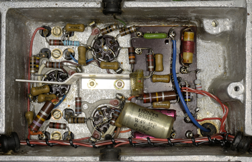
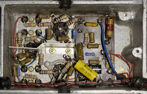
As previously mentioned, the RA117 has an additional IF stage inserted before the 100KHz IF. This encompasses the new 3rd and 4rth mixers stages, a 1.7MHz crystal oscillator and a buffer stage ... all of which is crammed into a relatively small volume, resulting in a module which is understandable tricky to work on. Deliberate use of small, hi-spec capacitors in some locations allowed for a less cramped interior, particularly o the tag-board. The module was tested on the bench prior to mounting back on the chassis.
3rd and 4th Mixer module, before
3rd and 4th Mixer module, after
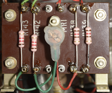
Like the RA17 etc., some of the under-chassis components are incredibly difficult to access or remove whilst the 1st and 2nd VFO modules are in place. This is largely due to the fact that various fixings are hidden under the VFOs. Below are photographs of these same parts in the RA117A, post-refurb.
Resistors on Harmonic Filter
Meter Rectifier tag board
Attenuator
With both VFOs and the 3rd & 4th Mixer module refurbished and re-tested it is now the turn of the 100KHz IF-Strip and BFO to be given 'the treatment'. As this module has the highest concentration of components it never fails to yield the highest number of out-of-spec resistors and 'iffy' capacitors.
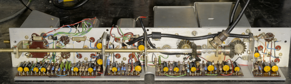
100KHz IF-Strip after refurbishment
Prior to removing the 100KHz IF module, I tested the receiver and confirmed that it was working, definitely slightly better than my initial test, but still a tad noisy. I also had a look at the EA76 AGC clamp diode attached to one of the screening panels. Unfortunately I couldn't see any characteristic heater-glow due to a large amount of gettering. The easiest way to verify heater integrity while the IF module was disconnected and off the chassis was to removed all the B7G valves from the IF and the BFO and check the continuity across the heater supply. It measured about 15-ohms, confirming that the EA76 heater was intact. The next stage was to remove the long shaft and gears. This normally requires the application of heat to soften the locking-compound on the 6 Allen screws securing the gears and collar to the shaft. These had definitely never been loosened since manufacture and for some reason one of the 0.05-inch screws on the collar was damaged and would not accept the Allen key. Fortunately, it hadn't been screwed all the way in and the collar came off when the second screw was loosened. I have to conclude therefore, that the thread for the damaged screw might have been damaged ... thus it never made contact with the shaft. Such was the damage that it was impossible to remove the screw. So when it was all reassembled, the collar was secured by only one screw, which isn't an issue since under normal operation there is no torque on the collar.
RA117 BFO module
Left: A photograph of the BFO module which sits atop the 4th IF Module. Note that this is a slightly different circuit to that in the RA17 etc. in that it uses a 6AK5 as opposed to an EF91. The output though is still more or less a square-wave. So uncouth!
Racal did have their own in-house test jig for the 100KHz IF module, and I will confess that since I own a genuine Racal 2nd VFO test jig and built my own 1st VFO test jig, I had contemplated building a test jig for the 100KHz module. However I concluded that it was far simpler to put the module back on the chassis and test it there.
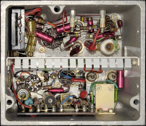
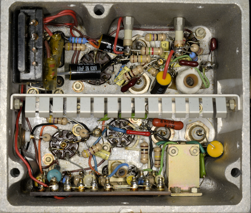
Once again, the receiver was tested. This time there was a notable decrease in system noise ... definitely a good sign! Now onto the remaining under-chassis circuits ... the first of these being the 1MHz Oscillator and Harmonic Generator. These two circuits share a compartment. Although essentially similar to the RA17 circuitry, 6AK5s are used instead of the ubiquitous EF91, thus there are some component changes. Also, there is a change in the design to allow for an external 1MHz i/p.
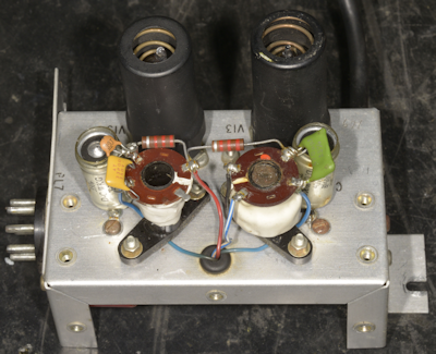
1MHz Oscillator and Harmonic Generator, before
1MHz Oscillator and Harmonic Generator, after
The output of the Harmonic Generator is fed through a 32MHz Low Pass filter into the Harmonic Mixer which is followed by two tuned amplifiers operating at 37.5MHz. See the photographs below.
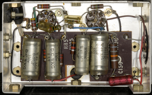
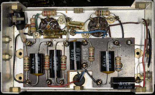
Harmonic Mixer and first two 37.5MHz amplifiers, before
Harmonic Mixer and first two 37.5MHz amplifiers, after
From the 'before' photograph, it is evident that at least two resistors had been previously replaced. The one on the right of the tag-board is actually in the HT feed for the 1st VFO, and since we know that someone in the past had experienced issues with that VFO, it is fair to assume that the failure of the original resistor on the tag-board was in some way related. The green silvered mica capacitor, which delivers the 1st VFO signal to the Harmonic Mixer, was found to be damaged, so I replaced it. No other issues were found in this compartment.
2nd Mixer and third 37.5MHz amplifier, before
2nd Mixer and third 37.5MHz amplifier, after
The output of the second 37.5MHz amplifier is not pretty and needs to be cleaned up. Thus, it is fed into an 8-pole loose-coupled band-pass filter tuned to 37.5MHz, the output of which is a 37.5MHz signal for every integer MHz on the MHz dial on the receiver.
L300 & L301: 37.5MHz and 1.6MHz traps
In the photographs above, the third and final 37.5MHz amplifier is on the left, the mixer is on the right. There are three differences in this compartment in the RA117 from the RA17. The 37.5MHz amplifier is an EF93, there is the inclusion of the terminal block on the far right, which is part of the 3rd & 4th Mixer module, and finally, not immediately visible in the photographs, there are a couple of signal wires feeding up through a hole in the tag-board to the 37.5MHz and 1.6MHz traps ... See the photograph on the left.
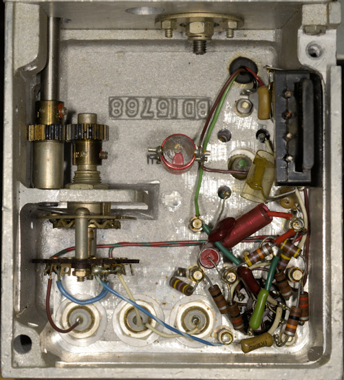
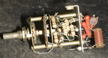
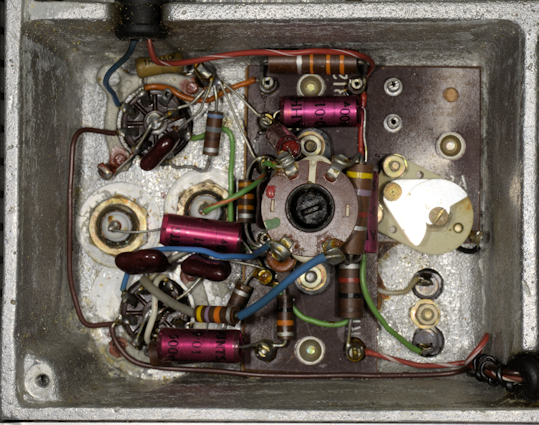
Let's not forget about the Calibrator, that often maligned little box that looks like it's poking out of the side of the 2nd VFO. For some reason, in the RA117, the Calibrator is turned 90 degrees, so that the valves are horizontal, and the L-bracket that normally gets screwed onto a Tufnol block on the 1st VFO now simply screws onto the rear of the film-scale carrier. Only, that's not how this one was attached. In this one, the knurled nut and screw that should have been on the side of the 2nd VFO was on the rear of the film-scale carrier, meaning that there was nothing to secure the module to the 2nd VFO. Someone had been 'busy'. Sorting this would be easy. On removal of the bottom top and bottom covers, I found that someone had definitely been experiencing calibrator issue ... hmmm?
note the two 'random' capacitors

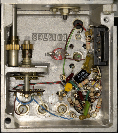
Correct value capacitor fitted (on right)
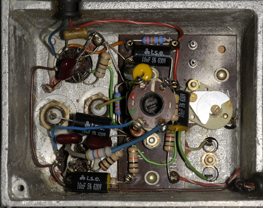
I have to assume that some previous owner had been trying to get the calibrator to function and was experimenting with the value of C117 (100pF). This had been replaced with 39pF in parallel with 33pF ... not going to work! So I replaced it with a silvered mica 100pF. As far as the rest of the calibrator was concerned, the only issue found concerned a couple of the 'Hunts' capacitors which had started to leak wax ... no surprises there. The Calibrator was tested and realigned on the bench, using the procedure described in the manual.
Calibrator inside, before
Calibrator inside, after
This may sound strange, but it isn't unusual to hear little 'cracks' when operating the System Switch on the RA117. This is the result of the HT rectifier being a solid-state bridge circuit rather than the thermionic GZ34 in the RA17 and RA17L etc. The exception to this is the North American RA17C-12, which actually had a solid-state bridge. Anyway, the reason for the cracking sound is the fact that the solid-state bridge has a much lower series resistance than the GZ34, which isn't surprising. When the switch is moved from Normal to AVC or from Standby to Normal, the HT is momentarily unloaded and then re-loaded, resulting in the crack.
This particular RA117A exhibited a different crack ... one which occurred as soon as it was switched on. NOT normal!
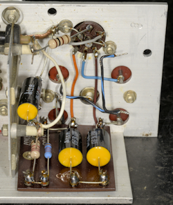
100KHz Buffer Stage tag-board
My initial suspicion was that it might be C108 in the third 37.5MHz amplifier flashing over (it is essentially between the anode of V10 and 0V). This capacitor can collect debris and occasionally shards of wire/solder-splashes, the result of which can result in HT shorting to ground ... and when that happens, R66 burns out! Removing C108 to clean it would have been a real pain as the tag-board would need to come out. I put the receiver on its side, turned the lights out, sat back and switched on, expectantly. To my relief, it wasn't C108. Instead there was a lovely flash in the region of the screen between the AGC (AVC) tag-board and Buffer amp tag-board on the 100KHz module. This turned out to be caused by shrinkage of the PVC insulation on at least one of the three wires entering the underside of three of the turret-tags (HT+, V17 Anode and V17 Screen) ... not much, but enough for the HT to 'jump' to 0V. It wasn't clear which was the culprit, and since all three wires showed insulation shrinkage, all three were dully pushed that little bit further into the underside of their respective turret-tags ... sorted!
Another fault which I picked up on manifested as a distinct lack of change in received signal strength when changing aerials. This turned out to be be a wiring error.
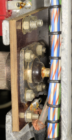
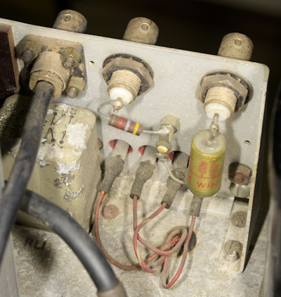
Incorrect wiring of SO-239
I'm not sure when this 'error' transpired, however there is an EMER that applies to RA17s etc. where the aerial connector was isolated from the chassis. This brought about the mounting of the connector on a Tufnol sheet.
I suspected a problem somewhere between the aerial connector and the attenuator. So, using a coax with crocodile clips at one end, I by-passed the coax between the aerial connector and the attenuator. That fixed the issue. So, the fault was definitely between the aerial connector and the attenuator. Using the same lead with croc-clips, I made connections to the SO-239 inner and the chassis. As with the previous test ... no fault. That's when I noticed how the SO-239 had been connected. The braid had been connected to the wrong screw. Instead of connecting to the SO-239 outer, it was connected to the screw which attached the Tufnol sheet to the chassis. Essentially, only one half of any aerial was being connected to the receiver. An easy mistake to make if you are not paying close attention. Also, this error could never be made when working on an RA17 fitted with the circular Burndept connector. Obviously, moving the solder tag corrected the issue.
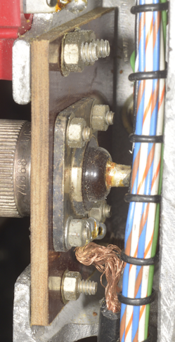
Correct wiring of SO-239
After a full realignment, which includes reshaping all the filters, including the critical 40MHz band-pass filter, RA117A N0959 more than exceeds Racal's original spec.
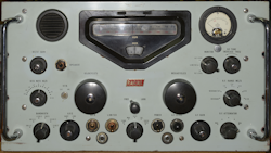
The finished receiver
Manufacturer’s specifications:
CW sensitivity: 18dB signal to noise for 1uV, 3KHz bandwidth
AM sensitivity: 18dB signal to noise for 3.5uV, 30% mod and 3KHz bandwidth.
RA117A N0959 now performs thus …
Freq.
1.6MHz
14.6MHz
28.6MHz
1.6MHz
14.6MHz
28.6MHz
CW
27.5dB
22dB
25dB
27.5dB
22dB
25dB
AM
22.5dB
22dB
22.5dB
22.5dB
22dB
22.5dB