Poor Man's MA350
3 minute read
This post is part of the series 'MA79 Drive Units':
Having spent at least a year getting to grips with the MA79 Transmitter Drive Unit, and using an MA79H as the basis for a previous article, it was necessary to generate stable signals at 1MHz and 200KHz in order to satisfy the input requirements for the MA79H. 1MHz and 200KHz are not necessarily difficult to achieve, although it is probably worth adding here that these two signals have to be very accurate and stable, and may be slightly beyond the capabilities of some older signal generators since the level required in each case is several volts p-p. My Adret 740A with the output set at maximum did manage to produce enough drive at 1MHz, whilst my HP 3325A was more than capable of delivering the required drive at 200KHz.
Anyway. I began thinking that there had to be a less hardware-intensive way to generate the two signals, which ideally had to be sine-waves. My first attempt involved a monolithic 1MHz TTL oscillator and the divide-by-5 part of a 7490 decade counter. This simple approach worked, as expected, but converting the TTL signals into sinewaves was always going to be not so easy, especially since the output of the 7490 was not a square-wave; it is in fact a series of pulses. Passing the TTL signals though a couple of filters did produce nice sine-waves but of a very low level, so amplification would be necessary ... not difficult, but this was getting away from my idea that it should be simple.
I then realised that the simplest solution was right in front of me. The RA17 etc. all feature a reliable crystal-controlled 1MHz oscillator and it struck me that it shouldn't be difficult to modify a standard 100KHz calibrator module to generate 200KHz. I had at hand, a 'never used' RA17 1MHz oscillator board and a used but surplus 100KHz calibrator. I removed from the oscillator board, all the components relating to the harmonic generator. I then replaced all the resistors and paper capacitors in the calibrator. Finally, I tested the 6BA6 and 6BE6. I even managed to find a Cathodeon crystal oven for the job!
Here's how it works ...
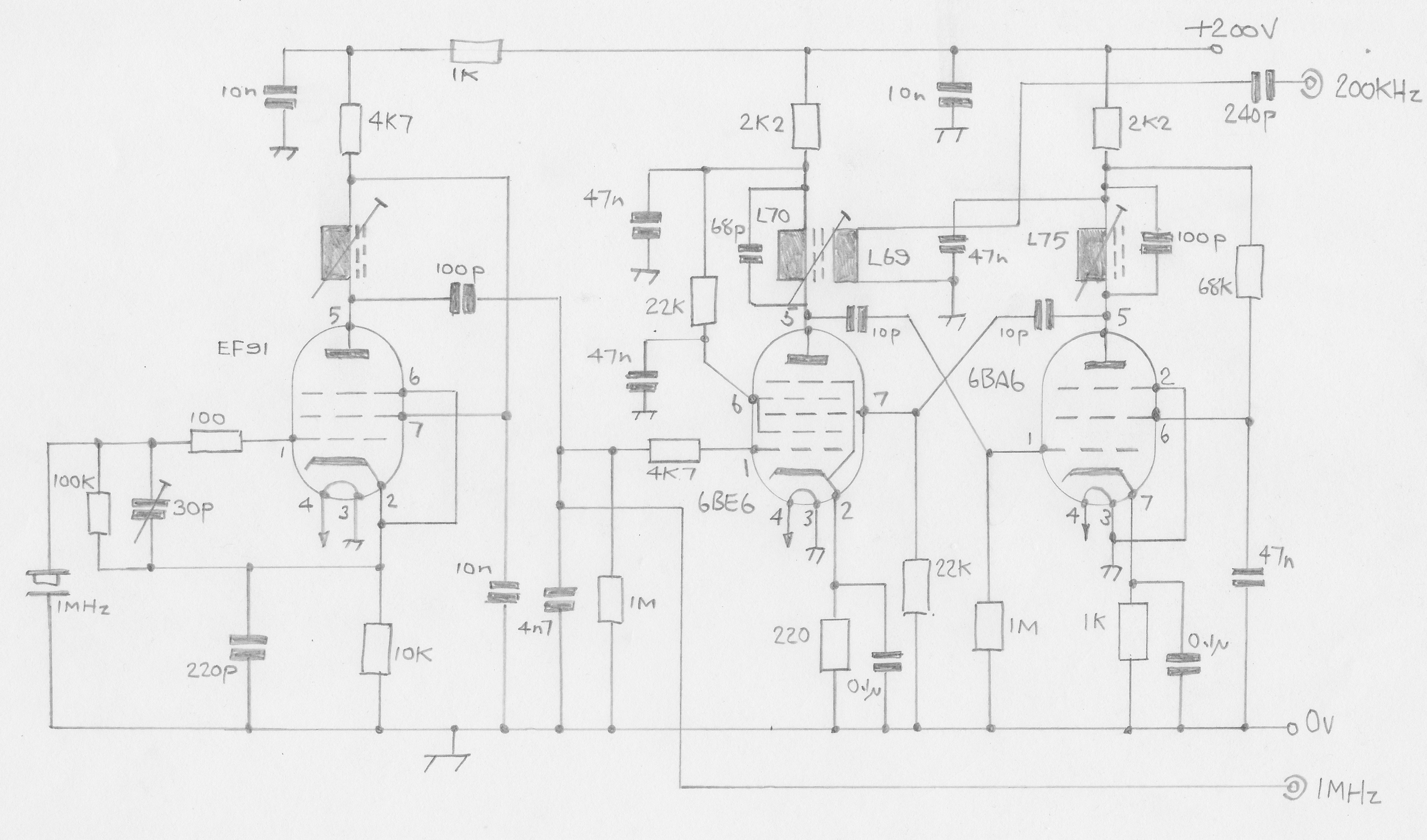
The output of the EF91 oscillator (1MHz) is taken to a BNC connector. It is also fed to the control grid of the 6BE6 whose anode circuit is tuned to 200KHz. A small sample of this signal is fed to the control grid of the 6BA6 multiplier whose anode circuit is tuned to 800KHz. Likewise a small sample of this 4th harmonic is fed back to the 6BE6 divider stage where it is mixed with the 1MHz signal, thus ensuring that the output is exactly one fifth of the 1MHz input. The only change that I had to make to the calibrator circuit was to replace the 470pF capacitor across L70 with a 68pF capacitor for it to resonate at 200KHz. There was enough range in L75 to retune it from 900KHz to 800KHz.
The 240pF capacitor in series with the 200KHz output was chosen such that the level of signal at the input to the MA284 was approximately 2V p-p. This circuit will actually work with an HT of 100V but probably best to run it from at least 200V and no more than 250V. The Cathodeon oven was configured for 6V and connected across the 6.3V heater circuit. Finally, if using this 'Poor Man's MA350, it will be necessary to temporarily disconnect the 68-ohm resistor found connected across the 1MHz input on the Octal connector that the MA284 plugs into.
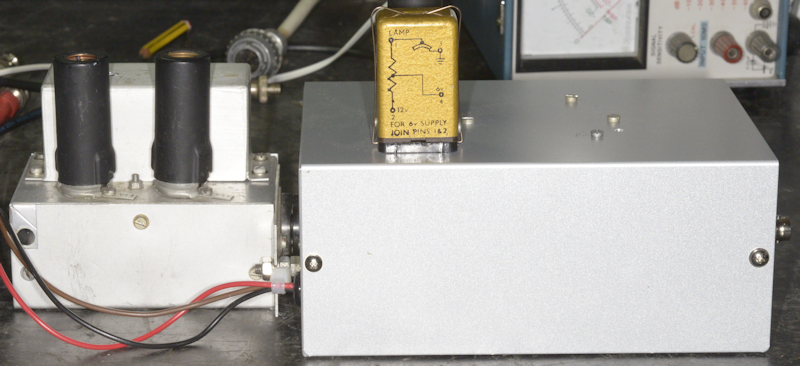
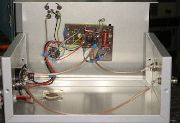
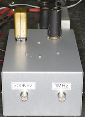
Two final views of my Poor Man's MA350. Definitely far simpler than my original TTL approach ... and the use of parts salvaged from an RA17 is arguably more appropriate.
Next post in the series: Fully Loaded MA79G
- The MA79 Transmitter Drive Unit
- Poor Man's MA350
- Fully Loaded MA79G
- Transmitter Drive Unit Type MA79H
July 2022
Having spent at least a year getting to grips with the MA79 Transmitter Drive Unit, and using an MA79H as the basis for a previous article, it was necessary to generate stable signals at 1MHz and 200KHz in order to satisfy the input requirements for the MA79H. 1MHz and 200KHz are not necessarily difficult to achieve, although it is probably worth adding here that these two signals have to be very accurate and stable, and may be slightly beyond the capabilities of some older signal generators since the level required in each case is several volts p-p. My Adret 740A with the output set at maximum did manage to produce enough drive at 1MHz, whilst my HP 3325A was more than capable of delivering the required drive at 200KHz.
Anyway. I began thinking that there had to be a less hardware-intensive way to generate the two signals, which ideally had to be sine-waves. My first attempt involved a monolithic 1MHz TTL oscillator and the divide-by-5 part of a 7490 decade counter. This simple approach worked, as expected, but converting the TTL signals into sinewaves was always going to be not so easy, especially since the output of the 7490 was not a square-wave; it is in fact a series of pulses. Passing the TTL signals though a couple of filters did produce nice sine-waves but of a very low level, so amplification would be necessary ... not difficult, but this was getting away from my idea that it should be simple.
I then realised that the simplest solution was right in front of me. The RA17 etc. all feature a reliable crystal-controlled 1MHz oscillator and it struck me that it shouldn't be difficult to modify a standard 100KHz calibrator module to generate 200KHz. I had at hand, a 'never used' RA17 1MHz oscillator board and a used but surplus 100KHz calibrator. I removed from the oscillator board, all the components relating to the harmonic generator. I then replaced all the resistors and paper capacitors in the calibrator. Finally, I tested the 6BA6 and 6BE6. I even managed to find a Cathodeon crystal oven for the job!
Poor Man's MA350 Schematic
Here's how it works ...
The output of the EF91 oscillator (1MHz) is taken to a BNC connector. It is also fed to the control grid of the 6BE6 whose anode circuit is tuned to 200KHz. A small sample of this signal is fed to the control grid of the 6BA6 multiplier whose anode circuit is tuned to 800KHz. Likewise a small sample of this 4th harmonic is fed back to the 6BE6 divider stage where it is mixed with the 1MHz signal, thus ensuring that the output is exactly one fifth of the 1MHz input. The only change that I had to make to the calibrator circuit was to replace the 470pF capacitor across L70 with a 68pF capacitor for it to resonate at 200KHz. There was enough range in L75 to retune it from 900KHz to 800KHz.
The 240pF capacitor in series with the 200KHz output was chosen such that the level of signal at the input to the MA284 was approximately 2V p-p. This circuit will actually work with an HT of 100V but probably best to run it from at least 200V and no more than 250V. The Cathodeon oven was configured for 6V and connected across the 6.3V heater circuit. Finally, if using this 'Poor Man's MA350, it will be necessary to temporarily disconnect the 68-ohm resistor found connected across the 1MHz input on the Octal connector that the MA284 plugs into.
Poor Man's MA350
Poor Man's MA350 - Inside.
Two final views of my Poor Man's MA350. Definitely far simpler than my original TTL approach ... and the use of parts salvaged from an RA17 is arguably more appropriate.
Poor Man's MA350 - Front.
Next post in the series: Fully Loaded MA79G