GM4CXM gets 13cm!
10 minute read
July 2009
Ray, GM4CXM, a good friend of mine was extremely fortunate to be given the makings of a 13cm transverter earlier in the year. The boxes in question were the SSB Electronics SLO13 (local oscillator), SRM13 (RX converter) and STM13 (TX converter). Back in the early 1980s these were ‘state-of-the-art’. Ray was of the impression that these had once formed part of a ‘mast-head’ transverter which wasn’t terribly well sealed to the elements. I joked that they looked like they had been stored at the bottom of the North Sea. Knowing that I like a challenge, Ray asked me if I would like to undertake the task of producing a 13cm transverter based on these boxes.
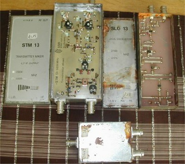
The 3 SSB Electronics boxes before renovation
The SRM13 in particular was so badly corroded that I had to use a hammer and chisel to get the lids off! Once ‘inside’ all three boxes, it was clear that I had some work ahead of me. The logical place to start was with the SLO13 Local Oscillator, which Ray had been told, had a tendency to self oscillate. However my main problem to begin with was that the U310 FET was not oscillating. When I did get it to ‘start’, I found that it was low in frequency and that the adjustment range was very limited. But at least it was something that I could work with. The next problem that I encountered was a clear indication that T3 (BFR90A) was faulty. This was replaced and the rest of the multiplier stages were tuned up with the aid of a simple volt-meter and my Systron-Donner spectrum analyser. The output was however very low and I soon found that C6 & C7 on the output of the 1st multiplier were incorrectly set and tuned to a secondary response. Once correctly set, both outputs of the SLO13 were well in spec. There was however an instability in the signal which was eventually traced to a faulty ceramic capacitor (C4, 2p2) between the oscillator and the 1st multiplier. This was replaced and a simple Murata crystal heater placed over the crystal for added thermal stability. Replacing the faulty capacitor cured the tuning range issue, but it was possible to ‘push’ the frequency by varying the supply voltage despite there being a 9V regulator in line. This turned out to be faulty and was replaced with an LM317LM and a couple of carefully chosen resistors ... Problem solved! Satisfied that we had a viable project, I carefully ‘cut’ the SLO13 from its corroded case and re-fitted it into a brand new identical tin-plate box, with one noticeable change ... I replaced the nickel-plated BNC connectors with gold-plated SMA ones. In fact I intended to replace the BNCs on all three boxes with SMAs for two reasons. Firstly, BNCs are fine for bench equipment but are somewhat cumbersome when used for internal connections. Secondly their performance at 2GHz is questionable. So they had to go.
Left: The SLO13 in its new shiny box. The LM317LM is top right. The pink wire is the 12V line to the Murata heater. Some extra decoupling has been added to the oscillator circuit.
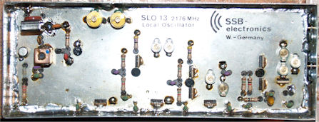
Not a bit of rust in sight!
The SRM13 was next in line and as with the SLO13, it took a few carefully aimed blows from a hammer and chisel just to get the top cover off! The tin-plate was completely gone and the lid was literally fused to the box by aggressive ferric oxide (plain old rust!). The bottom lid was only slightly corroded and came of easily and it was a simple job to cut the board out.
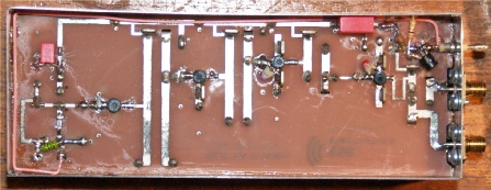
SRM13 PCB before
To be honest, I was quite taken aback by the state of the soldering on the SRM13. The soldering on the SLO13 by comparison was good. Whereas this was down-right shocking. Since both GaAsFETS were needing replaced it was a simple case of attacking the board with solder-wick and re-flowing every single joint. The photograph on the right speaks for itself.
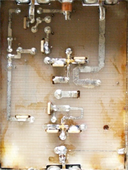
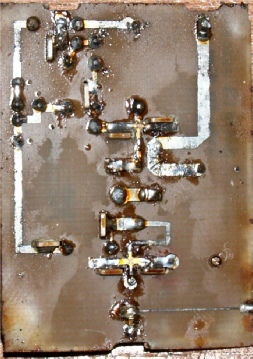
SRM13 PCB after cleaning
I didn’t have a suitable size tin-plate box but instead cut a larger one down to size. I replaced an over-size resistor with one the correct size and quickly found that both GaAsFETs were faulty. These were originally both MGF1200s which probably cost cost ‘an arm and a leg’ back in 1982. I replaced them both with MGF1302s (old stock, but new) and once I was satisfied that the bias currents were correct, I was pleased to find that the converter worked quite well. I don’t have a signal generator that goes beyond 1.12GHz, and at the time there wasn’t a ‘local’ beacon but I do have a personal beacon which I put into low power mode and tuned the SRM13 up on that. Curious to see what difference a HEMT would make in the front end, I replaced the ‘1302’ with an FHX14LG and despite the absence of an independent negative bias rail, the device actually outperformed the MGF1302 at 2.32GHz.
The STM13 (TX converter) was in relatively good condition, Ray having already cleaned most of the rust off. Since I didn’t have a similar size box available, I opted to work with it as it stood ... Once I replaced the BNCs with SMAs first though. Initial tests were promising with all stages tuning up more or less correctly, although the output was admittedly somewhat lower than expected ... About 20dB lower to be precise! What did strike me as odd was that P2, the mixer balance control was set to one end of its travel, indicating that there was a substantial difference between T2 and T3 (both BFR91A). Both transistors checked out more or less OK but after replacing both devices with new ones, P2 maximised mixer performance at more or less mid travel. This accomplished, the output of the STM13 was measured at just over 600mW.
The STM13 (TX converter) was in relatively good condition, Ray having already cleaned most of the rust off. Since I didn’t have a similar size box available, I opted to work with it as it stood ... Once I replaced the BNCs with SMAs first though. Initial tests were promising with all stages tuning up more or less correctly, although the output was admittedly somewhat lower than expected ... About 20dB lower to be precise! What did strike me as odd was that P2, the mixer balance control was set to one end of its travel, indicating that there was a substantial difference between T2 and T3 (both BFR91A). Both transistors checked out more or less OK but after replacing both devices with new ones, P2 maximised mixer performance at more or less mid travel. This accomplished, the output of the STM13 was measured at just over 600mW.
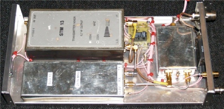
There are several disadvantages with modular designs like this. OK, this kit is almost 20 years old and it was indeed pioneering stuff in its day. But it does make for bulky projects by today’s standards. Secondly, there are no less than 8 coaxial connectors involved. Changing the BNCs for SMAs was quite expensive. Thirdly the user has to provide their own I/F switching and PTT control. In this case, I put together a small PCB incorporating PTT control along with DC and I/F routing. This is the little board situated to the right of the STM13. The antenna coax relay is just to the right of the SRM13.
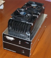
Ray took my advice and invested in one of Pyro Joe’s Spectrian PAs. These come in two flavours; Optimised for 26V and optimised for 12V. Ray opted for the high power 26V version. With about 800mW of drive at 2.3GHz, these PAs will deliver up to 60W, but at a price! Being Class-A in operation, they are gloriously inefficient. One estimate is 14%. As a result, a serious heat sink is necessary. Not only that, it is imperative that said heat sink is force-air-cooled. This isn’t a problem except that the heat sink more than doubles the weight of the transverter. That aside, the Spectrian PA is incredibly simple to implement. Two small rows of pins provide input for the Enable signal, Drain-current monitoring for the two output devices and a voltage which is proportional to the substrate temperature. This temperature related output can be used to switch on a couple of fans when the amplifier/heat-sink gets hot ... and believe me it gets hot, and it gets hot fast! The only problem with these boards is that they are bonded on to a solid copper heat spreader. It is easy to solder to the input and output tabs, but soldering to the ground-plane is a near impossibility due to the thermal conduction of the gold-plated copper heat-spreader. To get around this, I have devised a screw-down system for attaching the input and output coaxes. Like my own 13cm transverter, this one is built into 2 back-to-back boxes.
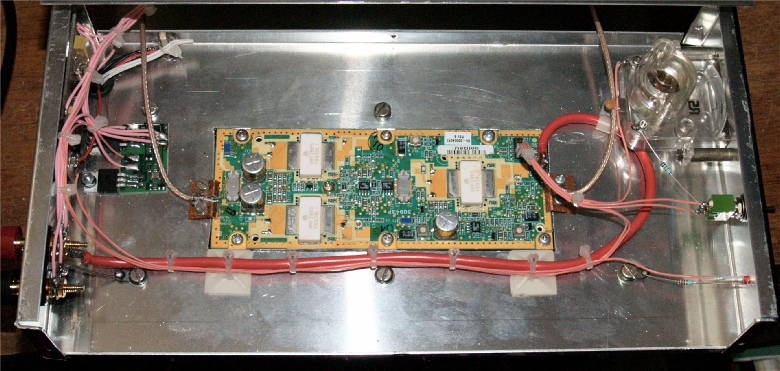
The finished Spectrian PA installed in the upper chassis
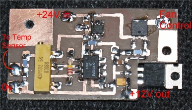
The photograph on the left is the fan-control and regulator PEC. Since the total current drawn by the SSB Electronics modules is never more than 800mA, a simple 1A 3-terminal 12V regulator is all that is required to step the 24V down to 12V. The board is mounted onto the rear of the upper chassis in such a way that the multi-turn pot can be accessed through a hole just behind the heat-sink. The 220K resistor in the feedback loop of the LM393 comparator provides about 15 degrees of thermal hysteresis. Thus if the fans are set to come on at 45 degrees Celcius, they will go off at about 30 degrees Celcius.
A DB6NT sequencer is used to control the SMA antenna relay and apply the PA-enable signal. The board in question is the SEQ-3 which is a bit of an over-kill, but the tabs on the MOSFETs make it easy to mount.
A DB6NT sequencer is used to control the SMA antenna relay and apply the PA-enable signal. The board in question is the SEQ-3 which is a bit of an over-kill, but the tabs on the MOSFETs make it easy to mount.
Setting up the PA shouldn’t present any problems although it can be a bit tricky setting up the bias on the two output devices. Joe suggests 2.5A (at 26V) for the driver and 2A each for the output devices (Q1 and Q2). I found that with a supply voltage of 24V (Ray’s PSU only delivers 24V), setting the bias current to 2A was problematic and interdependent. Whatever the reason for this, I found that a bias current of 1.8A per output device was easy to attain and was thermally stable. Applying drive from the STM13 TX converter resulted in about 5A Drain current for each of the two output devices, indicating that the PA was working well. I fitted a switch and a meter for Ray to monitor the PA current.
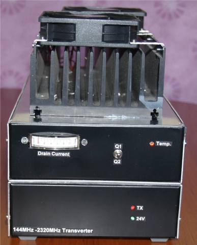
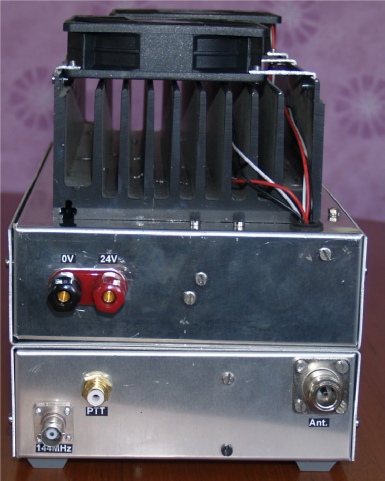
Front and Rear views of the finished 13cm transverter