The MA3752 Dual HF Drive Unit
3 minute read
This post is part of the series 'The Racal 3700 Series':
Next post in the series: The RA3702 Dual HF Receiver
- The RA3700 Series
- The RA3701 HF Receiver
- The RA3712 Dual HF Receiver
- The MA3752 Dual HF Drive Unit
- The RA3702 Dual HF Receiver
- The TA3762 250W Linear Amplifier
- The MA3772 1KW HF Combiner
- The MA3752 driving a TA3762 PA
September 2019
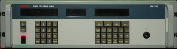
The MA3752 is effectively two MA3751 drive units in one chassis, sharing a common front panel which can be switched to control one drive unit at a time.
The frequency coverage is 1.5MHz to 40MHz in 1Hz, 10Hz or 100Hz steps. Operating modes include USB, LSB, Compatible AM and CW provided as standard, with ISB and True AM operation available as options. Suppressed or Pilot carrier may be selected for the sideband modes.
The MA3752 includes power amplifier control interface hardware, allowing it to be used in conjunction with a variety of Racal linear amplifiers. Where an ASCII interface is available, all amplifier functions, including BITE may be controlled from the MA3752 front panel. The RF drive output is set automatically to a level between +13dBm to +23dBm (20mW to 200mW) to suit the associated power amplifier.
Single function buttons control the most commonly used operations and four keys control the many special facilities by means of a menu system. Frequency selection is achieved by numeric keypad entry.A 100-channel non-volatile memory provides instant recall of 100 frequencies and their associated operating settings.
Comprehensive built-n test equipment (BITE) locates faults to module level and may be controlled remotely as well as locally fromthe front panel.
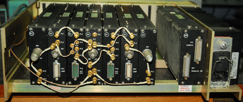
Basic MA3752 Dual Drive Unit Configuration
Above:
With reference to the bank of modules ... the one in the centre (A4) is the Dual 80MHz Reference Module. Drive unit 1 is then on the right with Driver Unit 2 on the left. Module A1 is the Modulator, A2 is the RF Output Module and A3 is the Synthesiser Module. The space on the far left is reserved for the optional FSK Module (A5) whilst the space between to the keft of the Processor module (A10) is reserved for the Optional IF Filter Module (A9).
As mentioned above, ISB and True AM operation is only available as an option. These modes are catered for via the optional ISB Modulator Module which is (according to the manual) physically identical to the Modulator Module. The only difference being that the Summing Amplifier is not used in the former. If ISB operation is required it is therefore necessary to fit both Modulator Modules. I can find no reference in the manuals as to where the optional ISB modules fit, nor if two can be fitted in the case of the MA3752. Although not clear from the extensive manual, It looks like that although the two free slots are marked as being reserved for the optional FSK and IF Filter Modules that their use is not exclusive and that the optional ISB modules may also be fitted in these free slots. If I am correct in this assumption, this is possible due to the use of automatic module detection (used across the entire 3700 series) whereby a unique module identification code is hard-wired into each module and is detected by the Processor when the system is switched on. This is further complicated when we take the optional IF Filter Module into account since a single IF Filter module can be used with both drive units in the MA3752. Therefore it may be possible to fit two optioanl ISB Modulators when the Optional IF Filter module is NOT fitted, but if the latter is fitted, then only one ISB modultator can be accommodated. I may be wrong, but as I said, the manuals are not clear on this matter.
Next post in the series: The RA3702 Dual HF Receiver