The SA97 Wobbulator
17 minute read
November 2015
Here’s a tip; If you want your precious RA17, RA17L, or RA117 to continue to give you excellent service, don’t twiddle with anything behind the front panel!
Actually, the same can be said for ALL multi-band HF receivers. However, in the case of the RA17 series, one minor careless tweak could leave your receiver seriously compromised. It’s not that the receiver is fiendishly complicated either, which it isn’t. Yes it contains around 25 valves. But to the trained eye, it is nothing more than a series of relatively uncomplicated building blocks connected together in such a way as to satisfy a very clever arithmetic function. The product of which is a rock steady receiver requiring no complicated band-changing switches.
A crucial element in making this possible is the 40MHz band-pass filter on the output of the 1st mixer. This is an 8-element over-coupled network giving a bandwidth of 40MHz +/- 650KHz. Unlike the 37.5MHz band-pass filter, itself consisting of 8 loose-coupled elements, which can actually be aligned simply by adjusting for maximum deflection on the front panel meter, the 40MHz filter can ONLY be aligned using specialised equipment.
So although RACAL, along with Dr. Trevor Wadley, had created a receiver that was arguably easier to physically manufacture than others of the day, it on the other hand posed a serious challenge when it came to first-time alignment. So they designed the SA.97 Visual Alignment Unit (to give it its official Racal name) specifically for this purpose.
A popular on-line encyclopaedia defines a wobbulator as ‘an electronic device primarily used for the alignment of receiver or transmitter intermediate frequency strips. It is usually used in conjunction with an oscilloscope, to enable a visual representation of a receiver's passband to be seen, hence simplifying alignment; it was used to tune early consumer AM radios. The term "wobbulator" is a portmanteau of wobble and oscillator.’
The SA.97 combined the ‘oscillator’ and ‘oscilloscope’ into one self-contained instrument which was by necessity, easy to operate.
I first saw this SA97 when visiting a friend about two years ago. It was sitting gathering dust on a shelf surrounded by other gems of Racal history. At the time, I made the comment that I would very much like to get my hands on it, to get it working, purely out of curiosity since I use the DG8SAQ VNWA for aligning the filters. So I was very pleasantly surprised when my friend gifted it to me last month (October 2015). I was forewarned that it didn’t work, but that didn’t deter me. The brilliance control had little or no effect and the amount of Y-shift was limited to the upper half of the screen. At least the CRT worked! Thus I had something to start with. But I had absolutely no documentation on it other than a very brief reference to it in a magazine article. No circuit diagrams or any indication as to how it achieved its purpose!
If you want information on anything, simply type it into Google and you will find what you are looking for. Well, I’m afraid that’s a myth. A search on the Internet for ‘SA97 wobbulator’ came up with little more than several documentation references and a couple of photographs. Ironically the photographs in question were of the same SA.97 that I am in possession of. How weird is that? It therefore goes without saying that the SA.97 is a very rare piece of Racal hardware indeed, by virtue of the fact that it was what is termed ‘in-house test equipment’ and was, I suspect, eventually superceded by the Samwell and Hutton CT-501.
The phrase ‘poke around’ is synonymous with fault finding, especially when you have limited information, However when there is potentially 4KV present, poking around takes on a whole new dimension. I found an open-circuit 1M resistor in the -2KV line. This however was not the cause of the dysfunctional Brilliance control. On the other hand, the cause of the restricted Y-shift was nothing more than a broken wire to the base of the CRT. Then I spotted the 100nF/2KV capacitor under the chassis that was covered in light oil! This was connected between the grid of the CRT and the Time-base circuitry. I replaced the capacitor with a modern high voltage one and this cured the fault with the Brilliance control. So, that was easy!
A quick test showed that the Sweep Oscillator worked and so did the Lin/Log Amplifier module. With the display now working all I had to do now was figure out how the SA.97 was actually used.
There are 4 connectors on the front panel; two BNC and two Pye connectors. A short BNC lead can be used to link the output of the 40MHz Lin/Log Amplifier to the Y-Input on the display. The Pye connectors are not the same as those found in the RA17 in that the inner part is a receptacle as opposed to a pin. I temporarily connected the output of the Sweep Generator (as Racal call it) to the input of the Lin/Log Amp via a tuned circuit that I knew had a response at 40MHz. This produced a response trace just as I had hoped. So I was definitely on-track for a working SA.97. However there is a distinct lack of means of calibration regarding the displayed output. There is however a small sub-chassis inside with four valves and a 40MHz crystal which I assumed formed a marker generator. Examination of the trace did indeed reveal a dark spot. While I was able to prove that this was coming from the circuit on the sub chassis, one marker was obviously insufficient. I later discovered that shortly after the unit was switched on there were actually two markers but one of them would slowly diminish after a few minutes.
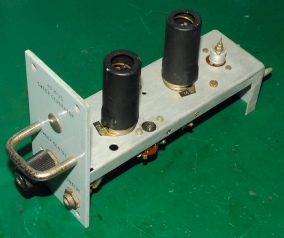
Marker Generator
As already said, the Marker Generator, employs four valves, one ECC81, two EF91s and an EFC80. The latter appeared to be faulty; the triode section causing the trip on my valve tester to assert. I didn’t have a spare, so I had to order one. In the interim I set about working out the circuit diagram ... not as hard as it looks. Once I had an idea of the different parts of the circuit, it was just a case of following the signals through each ‘block’ and trying to figure out why one of the pulses would diminish. I then decided to replace all the half-watt resistors under the little chassis. Some were about 50% high in value. I also replaced three 10nF decoupling capacitors and the 100nF output capacitor. The large 33K wirewound resistor is a bit of an enigma because it is in parallel with what was originally a half-watt 47K resistor. I think I have it in the right place! On putting it all back together again and with a new ECF80 fitted, the two visible markers remained constant, so I must have done something right. But only two markers still didn’t ‘feel’ right, so I played around with the two variable inductors. I figured it would be logical to have a centre marker and at least one on either side. So I also played around with the sweep width controls and finally got the trace in the photograph. Definitely one centre marker with two either side. Not bad for no circuit diagram and no idea how it worked!
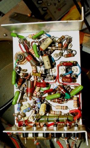
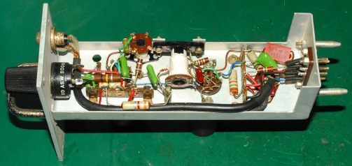
Marker Generator underside
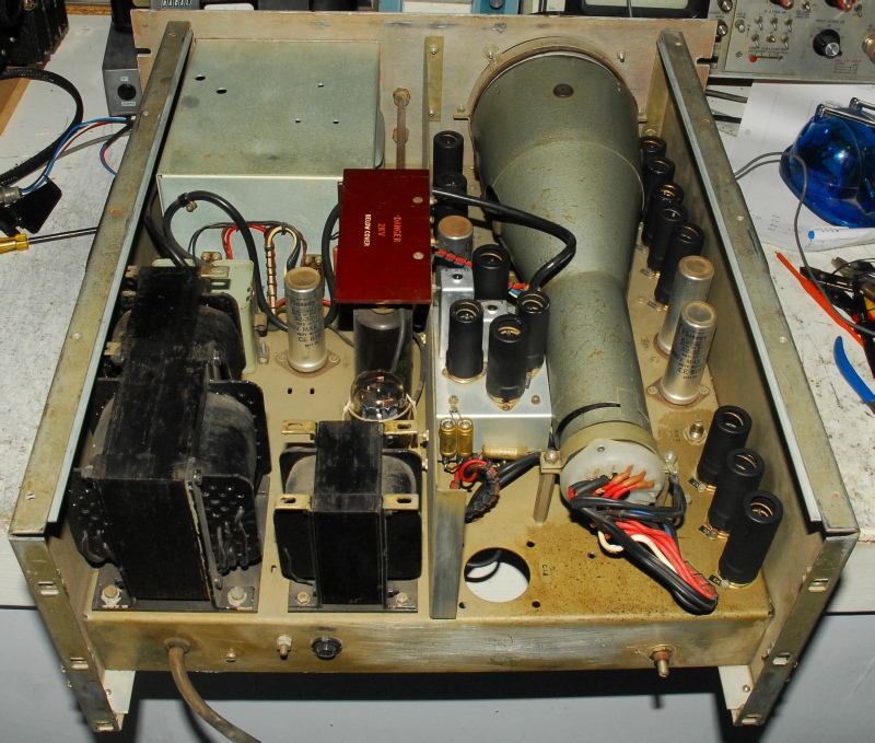
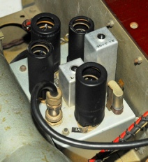
Above: The inside of the SA.97, beginning top left and continuing clock-wise: The RF plug-in enclosure, Y-Amplifier, CRT, Timebase generator, Astigmatism control and Voltage Stabiliser circuit, Marker Generator and finally the PSU. Note the dark stain in the corner of the chassis (bottom right). This is from the oil that leaked from the faulty 100nF capacitor. It is also possible that originally this capacitor may have been mounted where the round hole is, although there is no evidence that it was ever so. I would guess then that a smaller one was sourced and in this case, went on to fail. The lone potentiometer at the rear of the chassis is connected to the stabliser circuit (V3 and V6) and is used to set the HT to the the Lin/Log Amplifier to 210V. The HT rectifier is a 5V4G and the CRT is a DG13-2.
December 2015: Many thanks to Johan (PE1RHC) for providing a full schematic diagram for the SA97, which can be downloaded here.
December 2015: Many thanks to Johan (PE1RHC) for providing a full schematic diagram for the SA97, which can be downloaded here.
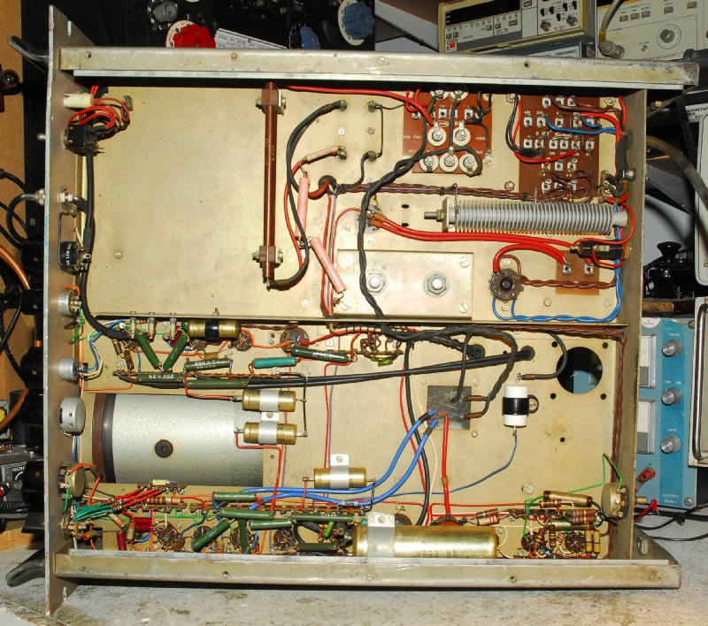
Above: The underside of the SA.97. The top half is clearly the PSU. There are two transformers and one choke. The metal rectifier serves to provide a negative voltage to complement the output of the 5V4G. This is necessary for symmetrical drive to each pair of deflector plates. Although not clear from the photograph, there are two EHT rectifiers (long thin Tufnol tubes). These provide -2KV and +2KV. The +2KV is purely for the post-deflection accelerator. The circuitry running across the centre is the Y-amplifier and -250V stabiliser circuit.
Across the bottom, left to right is the Timebase generator, +250V stabiliser circuit and +210V Stabiliser circuit.
The frequency marker pulses are ‘merged’ with the fly-back suppression signal which is connected to the grid of the CRT via the large (new 100nF/2KV) white capacitor.
I am told there were two sets of plug-ins for the SA.97 so that it could be used for setting up the 37.5MHz filter as well as the 40MHz filter. Whereas this may sound logical, as previously mentioned, the 37.5MHz filter does not require a wobbulator for alignment and what of the Marker Generator? It is clearly intended to work at 40MHz. Thus I have to conclude that unless someone can prove otherwise, I am guessing that the SA.97 was only ever fitted with 40MHz plug-ins.
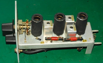
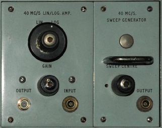
Above: 40MHz Sweep Generator, sync’d to the Sweep Timebase. A secondary RF output is fed to the Marker Generator.
Valves: 2 x ECC81
Valves: 2 x ECC81
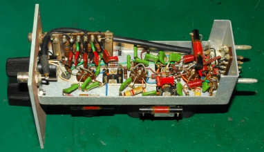
Above: 40MHz Lin/Log Amplifier. The output is fed via an external cable to the display Y-channel.
Valves: 3 x EF91
Valves: 3 x EF91
Other circuits:
Timebase and X-channel valve line-up: EF94, 12AU7, 2 xZ759, 150C4
Y-channel valve line-up: 2 x Z759, 150C4
Astigmatism control valve line-up: EF91, EL821, 85A2
Marker Generator valve line-up: ECC81, 2 x EF91, ECF80
Timebase and X-channel valve line-up: EF94, 12AU7, 2 xZ759, 150C4
Y-channel valve line-up: 2 x Z759, 150C4
Astigmatism control valve line-up: EF91, EL821, 85A2
Marker Generator valve line-up: ECC81, 2 x EF91, ECF80
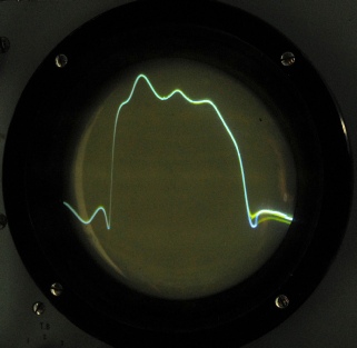
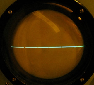
Finally … On the left is a photograph of the trace of a real 40MHz filter which was previously aligned using my DG8SAQ VNWA. Admittedly the pass-band ripple looks a bit excessive. However, much of that ripple can be attributed to cable length and termination. The markers are also not yet set correctly but the object of the exercise was to get a meaningful trace on the CRT and I think you will agree, that’s what we have here! … I’m dead chuffed.
As previously mentioned, the RF output from the Sweep Generator and the RF input to the Lin/Log Amp are unusual in that although they resemble the small connectors found on the rear of RA17s, they are in fact different since the centre conductor is a receptacle as opposed to a pin.
As can be seen from the photograph below, I managed to obtain a much better trace by fashioning short connections between the connector outer and the coax braid. In time I shall look into making dedicated leads for connection to TP2 and TP3 on the RA17. But until then I think you will agree it is quite fascinating to see this bespoke piece of test gear actually working.
More on the Marker Generator, left:
I now have the 5 markers correctly set. This was actually very easy to do. The way it works is remarkably simple. The smaller of the two variable inductors is used to set the centre marker on 40MHz (the Crystal Oscillator). The coax lead carries the auxiliary swept signal from the sweep oscillator. The taller of the two cans contains two tuned circuits in series which are themselves in series with the anode of one of the EF91s. I haven’t figured out precisely how it works, other than I can tell that some form of mixing is taking place, but the bottom core adjusts the +/-650KHz markers while the top core sets the +/- 1.5MHz markers. The markers were set by feeding known signals at 40MHz, 40.65MHz and 41.5MHz into the Lin/Log Amp input and adjusting the three cores. Signals at 39.35MHz and 38.5MHz were then applied to verify the other two markers.
Some final comments and observations …
I have been asked how I would compare the SA.97 to the Samwell & Hutton CT-501. The answer is simple. There is no real comparison since the SA.97 is essentially un-calibrated. There isn’t a single graduated control on the front panel and the display bears no graticule. Given my extensive array of test equipment, it would be possible for me to apply signals at known frequencies and levels and then draw lines on the Perspex CRT cover. Maybe this was how the display was calibrated, but it would need to be done every time the SA.97 was switched on and that is simply not practical and is likely to be the reason why I believe Racal themselves opted for the CT-501 in production.
I have been asked how I would compare the SA.97 to the Samwell & Hutton CT-501. The answer is simple. There is no real comparison since the SA.97 is essentially un-calibrated. There isn’t a single graduated control on the front panel and the display bears no graticule. Given my extensive array of test equipment, it would be possible for me to apply signals at known frequencies and levels and then draw lines on the Perspex CRT cover. Maybe this was how the display was calibrated, but it would need to be done every time the SA.97 was switched on and that is simply not practical and is likely to be the reason why I believe Racal themselves opted for the CT-501 in production.
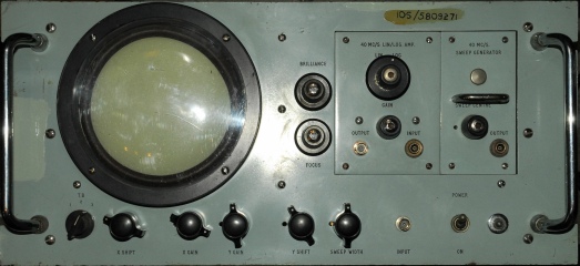
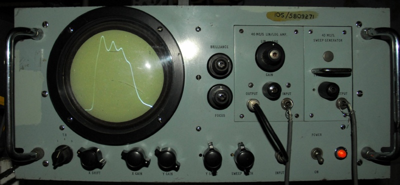
I thought it would be interesting to describe the controls on the SA.97. The Brilliance and Focus controls are self explanatory. The Sweep Generator has a single potentiometer control labelled ‘Sweep Centre’. As one would expect, this can be used to adjust the sweep such that the output is symmetrically centred on 40MHz. The pot shaft is slotted so it may be that in practice there was no knob on it. There is nothing behind the blanking cap.
The Lin/Log Amplifier module has a switch for selecting Linear or Logarithmic gain and an adjustable gain control. The latter only appears to be effective when ‘Lin’ is selected.
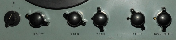
Along the bottom we have the X-Y controls. On the left there is the TimeBase control offering three different sweep rates. Next is the X-Shift which allows the user to move the entire trace left or right. Next is the X-Gain control which is ‘presumably’ used for setting the trace width to the diameter of the CRT. Then we have the Y-Gain control which as its name suggests, sets the vertical gain and thus the height of any displayed trace. The Y-Shift control allows the trace to be positioned anywhere in the Y-plane. The Sweep - Width control allows the user to ‘zoom’ in on a portion of the trace by limiting the range of the VCO control signal. For this it is necessary to make appropriate adjustment to the Sweep Centre control on the Sweep Generator. As you can see there is a distinct lack of annotation other than control labels.
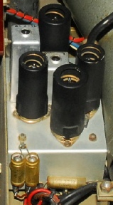
I have to admit that I find the SA.97 a rather odd piece of ‘Production Test Equipment’. I myself am ex-Racal and spent many years at what was then part of Racal Defence, latterly designing and building ‘Special Test Equipment’. Calibration was of paramount importance. So why the SA.97 is little more than a relative display is baffling to me? Something else which is worth pointing out is that this SA.97 is not as old as one would first assume. The early ‘bat-wing’ knobs as fitted on the RA17 MK1 might make you think that this is a relic from the 1950s. I initially thought this was the case and that the TimeBase knob, which is the same style as fitted to the RA1772, was only there because the original knob had been missing. However I now believe that the knob is original. As can be seen from the photographs in this article, ALL the quarter-watt resistors and nearly all the half-watt resistors are from the mid-late 1960s. The three tall electrolytic capacitors in the PSU are all dated May 1968; which is much later than I had expected. The RA1217 which was manufactured in the mid 1960s actually employs the same switch knobs as the RA1772, albiet a different colour. I doubt very much that this SA.97 was ever refurbished by Racal. Hence why I think the knob is original. So why did Racal go to the trouble of manufacturing this particular SA.97 in the late 1960s when significantly more accurate equipment was available ‘off the shelf’?
The Lin/Log Amplifier module has a switch for selecting Linear or Logarithmic gain and an adjustable gain control. The latter only appears to be effective when ‘Lin’ is selected.
Along the bottom we have the X-Y controls. On the left there is the TimeBase control offering three different sweep rates. Next is the X-Shift which allows the user to move the entire trace left or right. Next is the X-Gain control which is ‘presumably’ used for setting the trace width to the diameter of the CRT. Then we have the Y-Gain control which as its name suggests, sets the vertical gain and thus the height of any displayed trace. The Y-Shift control allows the trace to be positioned anywhere in the Y-plane. The Sweep - Width control allows the user to ‘zoom’ in on a portion of the trace by limiting the range of the VCO control signal. For this it is necessary to make appropriate adjustment to the Sweep Centre control on the Sweep Generator. As you can see there is a distinct lack of annotation other than control labels.
I have to admit that I find the SA.97 a rather odd piece of ‘Production Test Equipment’. I myself am ex-Racal and spent many years at what was then part of Racal Defence, latterly designing and building ‘Special Test Equipment’. Calibration was of paramount importance. So why the SA.97 is little more than a relative display is baffling to me? Something else which is worth pointing out is that this SA.97 is not as old as one would first assume. The early ‘bat-wing’ knobs as fitted on the RA17 MK1 might make you think that this is a relic from the 1950s. I initially thought this was the case and that the TimeBase knob, which is the same style as fitted to the RA1772, was only there because the original knob had been missing. However I now believe that the knob is original. As can be seen from the photographs in this article, ALL the quarter-watt resistors and nearly all the half-watt resistors are from the mid-late 1960s. The three tall electrolytic capacitors in the PSU are all dated May 1968; which is much later than I had expected. The RA1217 which was manufactured in the mid 1960s actually employs the same switch knobs as the RA1772, albiet a different colour. I doubt very much that this SA.97 was ever refurbished by Racal. Hence why I think the knob is original. So why did Racal go to the trouble of manufacturing this particular SA.97 in the late 1960s when significantly more accurate equipment was available ‘off the shelf’?
18 Nov. 2015:
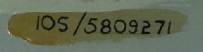
I am indebted to Andy Jackson, G8JAC for identifying the end user as the RAF
by deciphering the legend on the left thus …
I am indebted to Andy Jackson, G8JAC for identifying the end user as the RAF
by deciphering the legend on the left thus …
Section 10S is electronic test equipment. However, there was an interim period when the "last seven" digits of the Nato Stock Number were used, prefixed by the old stores catalogue section title. Now, electronic test equipment is NSN Class group 6625.
We know that it's British so the Nation code will be 99. Put all that together and we get: 6625-99-580-9271.
Put that into Google and Bingo! You will get cross-references to Racal Communications Systems Generator, Sweep, Type SA97.
So, your Wobbulator is (a) a Nato coded item and (b) it was used by the RAF.