Microdyne 1161-S Spectrum Display
10 minute read
April 2020
A couple of years ago I was given a load of electronic ‘junk’ that a friend was throwing out. Part of this trove included three mini CRT units bearing the identification ‘1161-S(A) Spectrum Display Unit’ manufactured by Microdyne.
Pieces of communications equipment with CRTs are ‘eye candy’ to a lot of people. The presence of the CRT adds a certain ‘want factor’. Take the Racal RA121 ISB adapter as an example. Nothing particularly brilliant about it other than it does what it was designed to do. The bandwidth is a little too wide for serious SSB work. BUT it has a CRT to aid centring the carrier in RTTY signals, and that makes it a rather sought-after item.
At the time I was particularly busy with other things such as RA17 refurbishments etc. so I did a quick internet search for ‘1161-S(A)’ and got nothing relating to the display … So, I simply ‘filed’ them away in a box under one of my workbenches and carried on with my ever increasing RA17 refurb workload.
However, with the current COVID-19 outbreak and resultant ‘lockdown’, work has slowed right down. A few RA17s which were scheduled to be delivered personally have obviously been put on hold and UPS have managed to misplace one at one of their hubs!! There’s a moral there … I think. As a result, I find myself with the time to focus on some of my personal projects.
So, after finishing the latest R1155 restoration, I heaved the box of ‘rainy-day projects’ out from under the bench. After repairing a Farnell D30 2T PSU and playing with a Thandar Function Generator (Q: Why do I need one of these when I have an HP3325A? A: You can never have too much test equipment.) I found myself pondering the three Microdyne displays and asking the question, ‘Can I find a use for these?’
A second quick search on the Internet instantly yielded a result … maybe because this time I'd searched for ‘1161-S display’? I found the service manual! The 1161-S is actually a very simple panoramic display with little or no ‘bells and whistles’. It has one sweep-rate and no selectable resolution other than an infinitely variable sweep range. It is simply intended as an aid to monitoring telemetry. It has no IF or base-band output. It is simply just a display.
The only external connection is via the composite ITT-Cannon D-Type connector at the rear for +/- 15V and 50MHz RF Input. Yes, 50MHz! Not a standard IF. This told me that the display was for use in something other than general communications. Further investigation revealed that it hailed from 1972 and was an optional plug-in for the Microdyne 1100-AR Telemetry Receiver, originally aimed at the emerging lunar missions and satellite business of the late 1960s and early 1970s. The 1100-AR would go on to become the workhorse for may tracking stations for the next three decades.
I was determined to power one of these up and assess its usefulness. Composite D-Type connectors are expensive so with the aid of the circuit diagram, I quickly worked out how to hard-wire the necessary supplies onto the back of the D-Type. I later discovered that a standard 15-way D-Type socket fits very nicely onto the bunch of pins, of which only 5 are used. I poked a wire into the coaxial socket, connected it to my Adret Signal Generator and fed in a low-level signal at 50MHz. It worked … Although increasing the frequency caused the resultant display to move to the left … a function of the display’s internal IF conversion. I also discovered that the Marker Generator in this particular display didn’t work.
As mentioned earlier, the 1161-S(A) is very basic. The sweep width can be varied between 100KHz and 6MHz. The sweep Rate is fixed at 20Hz and the Resolution Bandwidth is fixed at 10KHz. The input frequency is nominally 50MHz i.e. the ‘Center Freq’ front panel control can be used to align the 50MHz (Zero) Marker with the centre graticule line. The RF input is of 50-ohm impedance and quite sensitive at 10uV. The RF Gain control provides a very respectable 80dB of range. The Marker Generator (when working) provides a ‘Center’ marker at 50MHz with sidebands every 500KHz.
I originally hadn’t been aware that the Marker Generator was faulty until I read the bit in the manual about 500KHz sidebands as setting the switch to ON did produce the 50MHz marker. Investigation showed that the 500KHz oscillator was running but that there was no signal on the input to the 90MHz Pulse Modulator. This turned out to be caused by a short-circuit Tunnel Diode on the input to the Pulse Shaper. Who has Tunnel Diodes in their junk box?!
Tunnel Diodes were invented way back in 1957 at what is now Sony. Because of their unique construction, when forward-biased, an effect known as quantum mechanical tunnelling occurs where an increase in forward voltage is accompanied by a decrease in forward current. In theory ‘negative resistance’. In the 1161-S(A), this feature is used in the Pulse Shaper to produce a very fast rise time and thus produce many harmonics. Many of the original Tunnel Diode applications are now surpassed by more conventional semiconductor devices. However, Tunnel Diodes are still produced in small volumes.
Ironically, although Tunnel Diodes are susceptible to damage by overheating when soldering they are notable for their longevity. In some cases, the gold-plated iron wires/pins can corrode and short to the case and use of a peroxide and vinegar technique can often restore the diode. I investigated my shorted Tunnel Diode and sadly, if there is any such corrosion, it is inside the case and beyond hope. Fortunately, one of the three displays was labelled as faulty so I removed the Tunnel Diode from the IF board and used it to replace the shorted one. The Marker Generator now works a treat!
Given its purpose as a visual monitor in a telemetry receiver, and that such telemetry was more than likely from orbiting space vehicles, notably satellites etc. the fact that the resolution bandwidth is fixed at 10KHz makes a lot of sense. The bandwidth of such telemetry links is large by necessity in order to cram as much data as possible into the signal, hence no requirement for a narrow resolution bandwidth. There may even be times when the signal itself is several MHz wide.
I was asked if this monitor display could be hooked up to the IF output from a conventional HF communications receiver. The answer is off course, ‘yes it can’, provided some form of up-converter is employed. However, the 10KHz resolution bandwidth of the display renders it useless in this scenario for the following reason. Most receiver IF outputs are post-filter where the widest IF might be as low as 8KHz. So, with a resolution bandwidth only slightly wider than the IF bandwidth of the receiver, all you would see on the screen would be a ‘smoothed’ spectrum representation of perhaps one or two signals, depending on the mode in use.
The RF modules in the Racal 3700 series receivers have an output labelled ‘wideband IF OUT’. This unfortunately is not exactly true. In the 3700 series, the IF filters are in the IF/AF module, however there is a 12KHz roofing filter on the output of the 1st mixer, which is in the RF Module. So, although the port is labelled as wideband, it is subject to the bandwidth of the roofing filter, 12KHz. So, again, the display would be almost useless if connected here.
However, there is one thing which is, or can be wideband, and that is an aerial. I decided to investigate using the 1161-S(A) as an HF panoramic display. For this I would require an external wideband mixer and my Adret Signal Generator would provide the local oscillator. I have no shortage of wideband mixers and chose a Mini-Circuits ZFM-3 for the job. Since the 1161-S(A) has a sensitivity of 10uV, and the RF Gain range is given as 80dB, I decided that some additional gain was required for my experiment. Ideally I would want to be able to see signals in the region of -120dBm. I found a Mini-Circuits MAN-1LN which gives 30dB gain from 500KHz all the way up to 500MHz and another ‘gain block’ from Amplica Inc which proved to offer 25dB of gain. Both devices were tested on my network analyser and in each case the response was flat from below 100KHz to well above my desired upper limit of 30MHz. Assuming a maximum insertion loss in the mixer of 5dB, with both these amplifiers cascaded, the additional gain is potentially 50dB, enough for me not to need the RF Gain on the 1161-S(A) at maximum.
Now to connect it all together. As previously mentioned, the only connection to the 1161-S(A) is via a composite D-Type at the rear. There are a couple of holes either side of this connector for guide spigots and it struck me that one of these was just the right size for mounting an SMA connector. So I simply cut the coax to the coaxial insert and wired it to the newly fitted SMA female jack. The +/-15V for the supply and +15V for the dc-dc converter were rather ingeniously (so I think) connected via a standard 15-way D-Type socket which just happens to fit perfectly over the cluster of pins in the composite connector.
The local oscillator frequency needs to be HF of the RF input to the 1161-S(A) otherwise the resultant display will be ‘backwards’. Thus for the zero marker to correspond to 1MHz, the external LO must be set to 51MHz, or 64MHz for 14MHz. The display graticule has 6 horizontal divisions and it is logical to set the zero marker on the left. Since the calibration markers are at 500KHz intervals it makes sense to then set the first marker to the right of the zero marker 5 divisions to the right, thus providing a nominally calibrated frequency span of 600KHz. This is done by adjusting the ‘Center Freq’ and ‘Sweep Width’ controls accordingly. Once set, this should not require readjusting once the display is properly warmed up and stable. Then it is simply a case of applying the appropriate local oscillator signal for the frequency that you want the scan to start at. For this, I have a small USB-controlled programmable synthesiser on order and to complete the project I will look into fitting all the bits into a suitable enclosure.
Microdyne are still in business and still provide support for the 1100-AR Telemetry Receiver. See their website here which also shows the diverse range of plug-in RF Tuners that are still available.
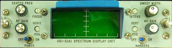
One of my Microdyne Spectrum Displays.
Pieces of communications equipment with CRTs are ‘eye candy’ to a lot of people. The presence of the CRT adds a certain ‘want factor’. Take the Racal RA121 ISB adapter as an example. Nothing particularly brilliant about it other than it does what it was designed to do. The bandwidth is a little too wide for serious SSB work. BUT it has a CRT to aid centring the carrier in RTTY signals, and that makes it a rather sought-after item.
At the time I was particularly busy with other things such as RA17 refurbishments etc. so I did a quick internet search for ‘1161-S(A)’ and got nothing relating to the display … So, I simply ‘filed’ them away in a box under one of my workbenches and carried on with my ever increasing RA17 refurb workload.
However, with the current COVID-19 outbreak and resultant ‘lockdown’, work has slowed right down. A few RA17s which were scheduled to be delivered personally have obviously been put on hold and UPS have managed to misplace one at one of their hubs!! There’s a moral there … I think. As a result, I find myself with the time to focus on some of my personal projects.
So, after finishing the latest R1155 restoration, I heaved the box of ‘rainy-day projects’ out from under the bench. After repairing a Farnell D30 2T PSU and playing with a Thandar Function Generator (Q: Why do I need one of these when I have an HP3325A? A: You can never have too much test equipment.) I found myself pondering the three Microdyne displays and asking the question, ‘Can I find a use for these?’
A second quick search on the Internet instantly yielded a result … maybe because this time I'd searched for ‘1161-S display’? I found the service manual! The 1161-S is actually a very simple panoramic display with little or no ‘bells and whistles’. It has one sweep-rate and no selectable resolution other than an infinitely variable sweep range. It is simply intended as an aid to monitoring telemetry. It has no IF or base-band output. It is simply just a display.
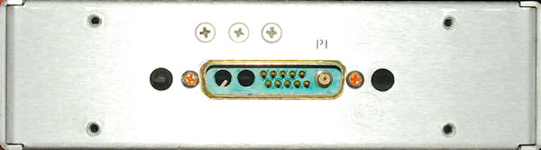
The composite D-Type at the rear of the display
The only external connection is via the composite ITT-Cannon D-Type connector at the rear for +/- 15V and 50MHz RF Input. Yes, 50MHz! Not a standard IF. This told me that the display was for use in something other than general communications. Further investigation revealed that it hailed from 1972 and was an optional plug-in for the Microdyne 1100-AR Telemetry Receiver, originally aimed at the emerging lunar missions and satellite business of the late 1960s and early 1970s. The 1100-AR would go on to become the workhorse for may tracking stations for the next three decades.
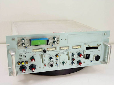
An example of a Microdyne 1100-AR Telemetry Receiver
I was determined to power one of these up and assess its usefulness. Composite D-Type connectors are expensive so with the aid of the circuit diagram, I quickly worked out how to hard-wire the necessary supplies onto the back of the D-Type. I later discovered that a standard 15-way D-Type socket fits very nicely onto the bunch of pins, of which only 5 are used. I poked a wire into the coaxial socket, connected it to my Adret Signal Generator and fed in a low-level signal at 50MHz. It worked … Although increasing the frequency caused the resultant display to move to the left … a function of the display’s internal IF conversion. I also discovered that the Marker Generator in this particular display didn’t work.
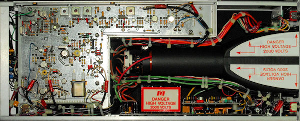
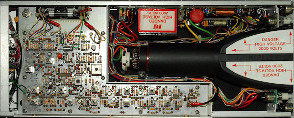
The 1161-S IF board.
As mentioned earlier, the 1161-S(A) is very basic. The sweep width can be varied between 100KHz and 6MHz. The sweep Rate is fixed at 20Hz and the Resolution Bandwidth is fixed at 10KHz. The input frequency is nominally 50MHz i.e. the ‘Center Freq’ front panel control can be used to align the 50MHz (Zero) Marker with the centre graticule line. The RF input is of 50-ohm impedance and quite sensitive at 10uV. The RF Gain control provides a very respectable 80dB of range. The Marker Generator (when working) provides a ‘Center’ marker at 50MHz with sidebands every 500KHz.
The 1161-S RF board.
I originally hadn’t been aware that the Marker Generator was faulty until I read the bit in the manual about 500KHz sidebands as setting the switch to ON did produce the 50MHz marker. Investigation showed that the 500KHz oscillator was running but that there was no signal on the input to the 90MHz Pulse Modulator. This turned out to be caused by a short-circuit Tunnel Diode on the input to the Pulse Shaper. Who has Tunnel Diodes in their junk box?!
Tunnel Diodes were invented way back in 1957 at what is now Sony. Because of their unique construction, when forward-biased, an effect known as quantum mechanical tunnelling occurs where an increase in forward voltage is accompanied by a decrease in forward current. In theory ‘negative resistance’. In the 1161-S(A), this feature is used in the Pulse Shaper to produce a very fast rise time and thus produce many harmonics. Many of the original Tunnel Diode applications are now surpassed by more conventional semiconductor devices. However, Tunnel Diodes are still produced in small volumes.
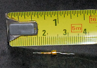
The faulty 1N3712 Tunnel Diode
Ironically, although Tunnel Diodes are susceptible to damage by overheating when soldering they are notable for their longevity. In some cases, the gold-plated iron wires/pins can corrode and short to the case and use of a peroxide and vinegar technique can often restore the diode. I investigated my shorted Tunnel Diode and sadly, if there is any such corrosion, it is inside the case and beyond hope. Fortunately, one of the three displays was labelled as faulty so I removed the Tunnel Diode from the IF board and used it to replace the shorted one. The Marker Generator now works a treat!
Given its purpose as a visual monitor in a telemetry receiver, and that such telemetry was more than likely from orbiting space vehicles, notably satellites etc. the fact that the resolution bandwidth is fixed at 10KHz makes a lot of sense. The bandwidth of such telemetry links is large by necessity in order to cram as much data as possible into the signal, hence no requirement for a narrow resolution bandwidth. There may even be times when the signal itself is several MHz wide.
I was asked if this monitor display could be hooked up to the IF output from a conventional HF communications receiver. The answer is off course, ‘yes it can’, provided some form of up-converter is employed. However, the 10KHz resolution bandwidth of the display renders it useless in this scenario for the following reason. Most receiver IF outputs are post-filter where the widest IF might be as low as 8KHz. So, with a resolution bandwidth only slightly wider than the IF bandwidth of the receiver, all you would see on the screen would be a ‘smoothed’ spectrum representation of perhaps one or two signals, depending on the mode in use.
The RF modules in the Racal 3700 series receivers have an output labelled ‘wideband IF OUT’. This unfortunately is not exactly true. In the 3700 series, the IF filters are in the IF/AF module, however there is a 12KHz roofing filter on the output of the 1st mixer, which is in the RF Module. So, although the port is labelled as wideband, it is subject to the bandwidth of the roofing filter, 12KHz. So, again, the display would be almost useless if connected here.
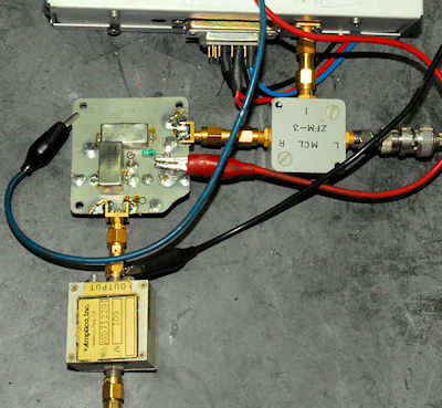
However, there is one thing which is, or can be wideband, and that is an aerial. I decided to investigate using the 1161-S(A) as an HF panoramic display. For this I would require an external wideband mixer and my Adret Signal Generator would provide the local oscillator. I have no shortage of wideband mixers and chose a Mini-Circuits ZFM-3 for the job. Since the 1161-S(A) has a sensitivity of 10uV, and the RF Gain range is given as 80dB, I decided that some additional gain was required for my experiment. Ideally I would want to be able to see signals in the region of -120dBm. I found a Mini-Circuits MAN-1LN which gives 30dB gain from 500KHz all the way up to 500MHz and another ‘gain block’ from Amplica Inc which proved to offer 25dB of gain. Both devices were tested on my network analyser and in each case the response was flat from below 100KHz to well above my desired upper limit of 30MHz. Assuming a maximum insertion loss in the mixer of 5dB, with both these amplifiers cascaded, the additional gain is potentially 50dB, enough for me not to need the RF Gain on the 1161-S(A) at maximum.
The external mixer & pre-amps 'lash-up'.
Now to connect it all together. As previously mentioned, the only connection to the 1161-S(A) is via a composite D-Type at the rear. There are a couple of holes either side of this connector for guide spigots and it struck me that one of these was just the right size for mounting an SMA connector. So I simply cut the coax to the coaxial insert and wired it to the newly fitted SMA female jack. The +/-15V for the supply and +15V for the dc-dc converter were rather ingeniously (so I think) connected via a standard 15-way D-Type socket which just happens to fit perfectly over the cluster of pins in the composite connector.
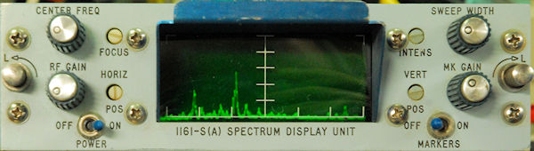
14.0MHz - 14.6MHz.
The local oscillator frequency needs to be HF of the RF input to the 1161-S(A) otherwise the resultant display will be ‘backwards’. Thus for the zero marker to correspond to 1MHz, the external LO must be set to 51MHz, or 64MHz for 14MHz. The display graticule has 6 horizontal divisions and it is logical to set the zero marker on the left. Since the calibration markers are at 500KHz intervals it makes sense to then set the first marker to the right of the zero marker 5 divisions to the right, thus providing a nominally calibrated frequency span of 600KHz. This is done by adjusting the ‘Center Freq’ and ‘Sweep Width’ controls accordingly. Once set, this should not require readjusting once the display is properly warmed up and stable. Then it is simply a case of applying the appropriate local oscillator signal for the frequency that you want the scan to start at. For this, I have a small USB-controlled programmable synthesiser on order and to complete the project I will look into fitting all the bits into a suitable enclosure.
Microdyne are still in business and still provide support for the 1100-AR Telemetry Receiver. See their website here which also shows the diverse range of plug-in RF Tuners that are still available.