A Power Supply for the T1154/R1155
8 minute read
January 2012
The purpose of this article is not so much as to present a specific design for a power supply … it is instead presented as a series of suggestions, since it evolved over a period of time and is largely made up of parts which just happened to be ‘lying around’. Initially it only consisted of the ‘middle’ section and was built specifically to run my newly restored A.D. 8882B (aka prototype R1155). At that time, there was no 24V supply, and instead there was a separate ‘beefy’ 6.3V transformer on the chassis. Contrary to what some people say, it is perfectly feasible to run the R1155 heaters from 6.3V AC. The fact that all the original drawings give the heater supply as LT+ and LT- is simply because the supply on the bomber was produced by dynamotors, which by their very nature were only capable of producing DC. It is a myth that the R1155 was not wired for AC and that using AC will result in excessive hum.
With the unexpected acquisition of a T1154M transmitter in 2010, I was suddenly presented with an new set of power supply requirements. I eventually came up with the idea that not only should it power the T1154 and the R1155, but that it should, as much as possible, actually mimic the supply onboard the bomber.
With the unexpected acquisition of a T1154M transmitter in 2010, I was suddenly presented with an new set of power supply requirements. I eventually came up with the idea that not only should it power the T1154 and the R1155, but that it should, as much as possible, actually mimic the supply onboard the bomber.
 HT Supply 24V, 220V Supplies & Audio Stage 6V Supply
Protect the heaters!
As previously said the heaters in a T1154/R1155 installation ran off 6V (nominal) DC. This becomes mandatory as soon as a T1154 is included since the same 6V that supplies the heaters, also energises the three coils in the T/R relay. If you were to try to substitute an AC supply, the T/R relay would subsequently sound like a door-bell! … on TX and RX! So don’t try it.
I won’t go into the design of the 6V supply right now except to say that I was a bit paranoid should the series regulator fail and the heaters in the transmitter and receiver be subjected to the raw DC from the rectifier (~12V). This would undoubtedly be an expensive failure, so I automatically built in a well tried and tested ‘over-voltage’ protection circuit. It was at this point that I realised just how simple it would be to make the PSU mimic the supply on the bomber.
I won’t go into the design of the 6V supply right now except to say that I was a bit paranoid should the series regulator fail and the heaters in the transmitter and receiver be subjected to the raw DC from the rectifier (~12V). This would undoubtedly be an expensive failure, so I automatically built in a well tried and tested ‘over-voltage’ protection circuit. It was at this point that I realised just how simple it would be to make the PSU mimic the supply on the bomber.
 PSU Start and Protection circuitry
How it works ...
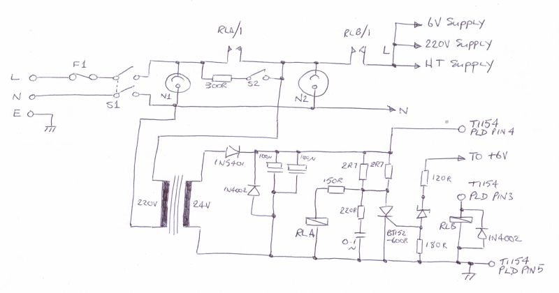
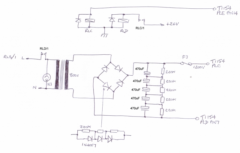
The mains supply takes the place of the dynamo attached to the port inboard engine (the starboard inboard engine drove the hydraulics, in the case of the Lancaster). Momentarily closing S2 is like connecting the dynamo to the large on-board lead-acid accumulator which was invariably 24V. Current flows in the primary of the transformer. A crude rectifier and smoothing circuit then generates approximately 24V DC and relay RLA energises. When the relay closes, S2 and the 300R resistor are shorted out. However, no other supplies are ‘up’ yet since the LT and HT dynamotors were controlled by way of the System Switch on the T1154. When the System Switch is moved to ‘STBI’, +24V is applied to relay RLB via PLD pin 3 on the front of the T1154. When RLB closes, the mains supply is finally routed through to the 6V, 220V and HT power supplies. However, there is a further interlock involved with regards the HT (typically 1200V) supply, so at this point the HT supply is not running since, in the bomber, the HT dynamotor was not switched on until the System Switch was set to ‘TUNE’.
The way the protection circuit works is very simple. The level of the 6V supply is monitored by way of the Zener diode via the 120R resistor. The value of the zener (I think 6.8V) is chosen such that should the 6V supply exceed 7.5V, the potential divider formed by the inclusion of the 180R resistor at the gate of the thyristor, causes the thyristor to ‘fire’ and thus ‘steal’ current from the relay (RLA). When this occurs, the contacts RLA/1 open, the 24V supply fails and ALL the relays in the PSU de-energise and ALL the supplies drop to zero volts … thus protecting the T1154 and R1155 heaters from over-voltage.
The way the protection circuit works is very simple. The level of the 6V supply is monitored by way of the Zener diode via the 120R resistor. The value of the zener (I think 6.8V) is chosen such that should the 6V supply exceed 7.5V, the potential divider formed by the inclusion of the 180R resistor at the gate of the thyristor, causes the thyristor to ‘fire’ and thus ‘steal’ current from the relay (RLA). When this occurs, the contacts RLA/1 open, the 24V supply fails and ALL the relays in the PSU de-energise and ALL the supplies drop to zero volts … thus protecting the T1154 and R1155 heaters from over-voltage.
Much current at 7V required ...
 6V DC Supply
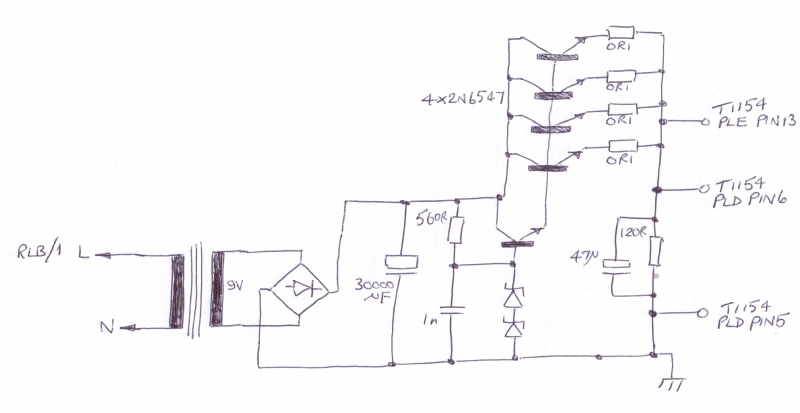
According to A.P. 2548A, the LT dynamotor was designed to deliver 7V at 13A. The two VT104 pentodes in the T1154 draw 2.6A between them, the two VT105 triodes draw a further 2A (almost). The R1155 alone could draw up to 4.4A. All this doesn’t add up to 13A, but don’t forget the 1200V dynamotor, where the internal solenoid to connect the 12V or 24V was supplied from the LT dynamotor, as were the T/R relay and the HT supply interlock relay.
The diagram above is fairly crude. A simple rectifier and smoothing pack, a zener diode voltage reference and high-gain series regulator. Everything with the exception of the mains transformer came out of the ‘junk box’. The exact value of zener is set such that the on-load output voltage is as close to 6.3V as possible. I think it is in the region of 7.5V in this case. The actual value will depend on the nature of the series regulator.
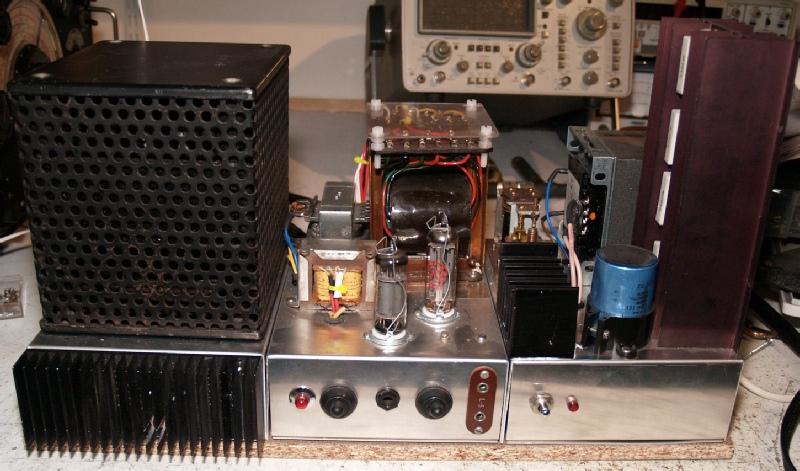
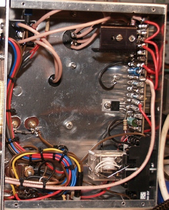
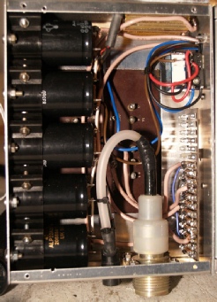
See the photograph on the left … RLA is bottom right. RLB, a genuine WW2 relay, is mounted on top of the chassis but the terminals can be seen bottom left. The regulator and over-voltage protection circuit are on the tag-board.
Honestly, I don't like high voltages ...
 HT (1200V) Supply & Interlock
This is really a very simple power supply. Initially I intended to use a stack of zener diodes to limit the output to 1200V, which is why there is a big metal-clad resistor at the top of the photograph, and why there is a heat-sink on the front of the chassis. Then I did the maths and realised that I couldn’t afford that many high power zeners.
Each side of the full-wave bridge rectifier is made up of three 1N4007s in series, each with a 220K resistor across it. Similarly the smoothing pack consists of five 470uF capacitors in series with 220K voltage matching resistors. That amounts to approximately 94uF, give or take the relative wild tolerances of electrolytic capacitors. I have had the transformer since the 1970s and back then it powered my 2m linear. It is actually a 500 - 0 - 500 secondary. However once rectified, that unfortunately produces over 1400V. So I have wired it so that only one half of the secondary is used and the on-load voltage is closer to 770V now … adequate for getting about 30W out of the T1154 on 80m. Ideally you should be looking for an 800V/200mA secondary. The HT dynamotor was not switched on until the System Switch was set to ‘TUNE’ and subsequent positions. This also involved an interlock via the J-Switch through Plug E on the side of the transmitter. Since the only low voltage present at that time in the transmitter is 6V, the HT start-relay is powered not from 24V but 6V. I didn’t have a 6V relay with suitable contacts, so I used a small 6V relay (RLC) to route +24V to a high power 24V relay (RLD).The beautiful high-voltage connector was obtained on eBay!
220V Supply and Valve Audio Stage ...
 220V Supply & Audio Amplifier
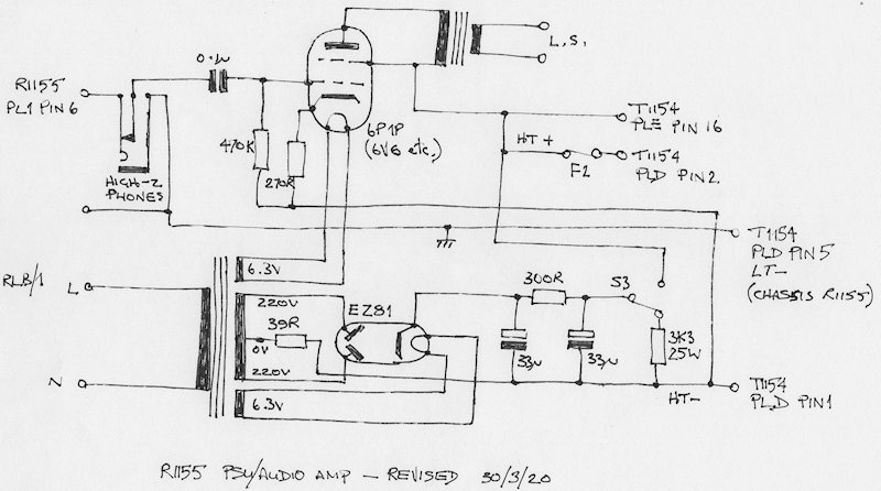
The audio output from the R1155 is designed for high-Z headphones. The noise in a Lancaster bomber (Halifax or Stirling) was unbelievable! The operator had to wear headphones, a loudspeaker would have been totally impractical. However, here is a really simple beam-tetrode design to accommodate a loudspeaker. I used a Russian 6P1P which has characteristics similar to a 6V6 or 6AQ5.
Note that in the PSU, the -ve side of the 220V is NOT connected to the chassis. This is because in the R1155, the chassis actually ‘floats’ to allow a -ve bias of about 30V to be produced. The 39R resistor is chosen to match the characteristic of the valve rectifier, in this case an EZ81. I didn’t have a suitable smoothing choke, and if I did, I doubt I would have had room for it, so I simply put a 300R resistor between the two 33uF capacitors. Quite by chance, the on-load voltage is 217V which is precisely the output of the dynamotor. S3 and the 3K3 resistor serve to provide a ‘Standby’ facility. A jack socket is provided for high-Z headphones. This is actually necessary when operating the T1154 in CW or MCW mode since the side-tone is fed to the R1155 audio stage and is too loud for me via the loudspeaker!