Using the Rigol DSA815-TG to align filters in the RA17 series
10 minute read
March 2021
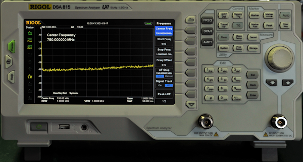
I recently invested in a new spectrum analyser, a Rigol DSA815-TG, to be precise. The thing is, I already have a more than adequate, albeit old, Systron-Donner 809-1, which covers 10MHz right up to 12.4GHz in 5 switchable ranges. The spec. for the DSA815-TG is 9KHz to 1.5GHz. Given that my Systron-Donner didn’t cost me anything back in the early 80s, and the fact that I have recently resolved a frequency accuracy issue, what was my reasoning behind the new investment?
This came about as a result of an email exchange with a fellow RA17 enthusiast. We had been discussing the test equipment that we each used for aligning the filters, in particular, the infamous 40MHz Band-Pass filter. The Rigol DSA815-TG (TG refers to the built-in Tracking Generator) was mentioned as a suitable modern alternative to the gargantuan Samwell & Hutton CT501, which I will add, I don't have. But I do have a Racal SA97 wobbulator, which is actually more interesting than useable.
Over the years, I have heard people refer to the combination of spectrum analyser and tracking generator as the way to go when tackling the 40MHz filter. However, although recognising the truth in the statement, I never gave it much thought, since for the last 10 years, I have been using a DG8SAQ VNWA for aligning these filters, and others.
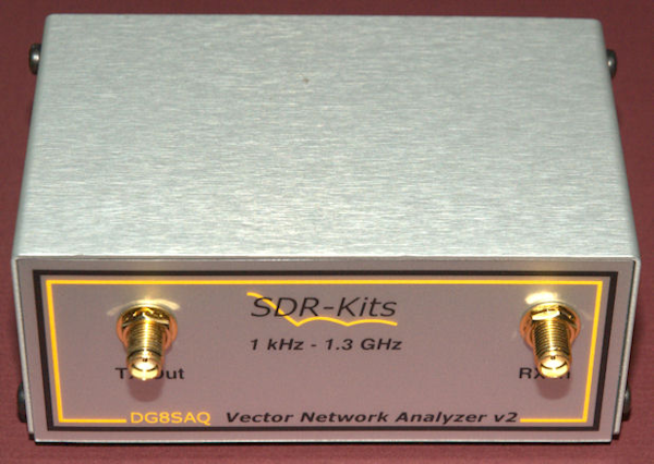
My DG8SAQ VNWA, built from a kit in 2010
So, with my DG8SAQ VNWA proving invaluable where the various filters in the RA17 were concerned, and the old Systron-Donner 809-1 continuing to give good service, just what was it about the DSA815 that was so appealing? Two things really: Convenience, and the ability to make direct power measurements. Last things first, the 809-1 does not have the ability to set a reference level, thus all measurements are purely relative.
The DG8SAQ VNWA is quite tiny compared to the DSA815, yet implementing it into my test setup is not quite as convenient as the DSA815. This is because since the VNWA is a USB device, it requires connection to a PC, which in my case is an old XP-based machine sitting under my desk at one end of the workshop. I have two monitors connected to this PC and one of those is strategically attached to the side of my test equipment rack.
Since my VNWA has been ‘married’ to a transfer relay, effectively turning it into an s-parameter test-set, I have not one but two USB cables running half-way round the workshop between the PC and the VNWA. There is also the need to have the VNWA disconnected from the PC at boot-up, otherwise it fails to boot … and the fact that the VNWA and the transfer-relay USB controller must always be plugged into specific USB ports, otherwise the VNWA is not detected. All this isn’t a problem, its just a little bit inconvenient. The thought of having everything in a single box sounded so convenient. Hence, why I invested in the Rigol DSA815-TG.
The RA17 series of receivers rely heavily on filters. The two key filters are the 40MHz filter on the output of the first mixer and the 37.5MHz filter on the output of the Harmonic Generator. Theoretically, the latter can be aligned (or re-aligned) simply by adjusting each trimmer for maximum reading on the front panel meter. Although I have encountered several cases where the actual filter response was significantly high in frequency. The over-coupled 40MHz filter cannot be aligned without the use of a suitable wobbulator.
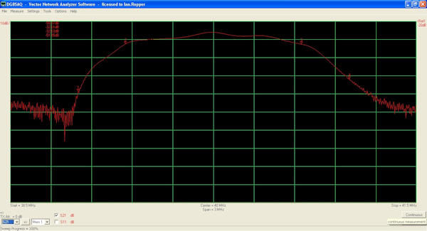
Example of 40MHz Filter aligned using the DG8SAQ VNWA
Then there are the 100KHz IF filters. The procedure in the manual for aligning these was written at a time when sophisticated test equipment did not exist. Thus, the method is very tedious and time consuming, requiring the technician to take several measurements, convert them into a graph and then do this several times until the required shape is achieved!
For ten years, I’ve been using the VNWA to align the 100KHz filter bandwidths in real-time. This is especially useful when it comes to the crystal lattice-filters, where achieving symmetry and minimising side lobes is greatly simplified. It was also this method which alerted me to the loose ferrite puck inside one of the inductors in the L-C filter.
I was looking forward to seeing how well the DSA815-TG fared at this task. I had no doubts concerning the 37.5MHz and 40MHz filters. But there was a question regarding its use at 100KHz, since according to the specifications, although the analyser range is 9KHz to 1.5GHz, the Tracking Generator range is only 100KHz to 1.5GHz.
Since the lower limit of 100KHz appears in all the advertising information and specification sheets, I believe this to be either a ‘typo’ or simply someone being conservative, since I have had the Tracking Generator working right down to 50KHz, with the level only beginning to drop off below 45KHz. As a consequence, it works beautifully at 100KHz, such that setting up the IF bandwidths in an RA17 is a breeze!
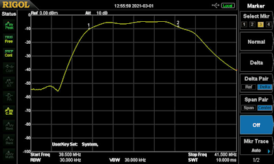
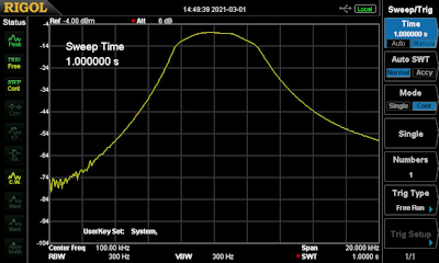
Left: The 40MHz filter in a recently refurbished RA17L as aligned using the Rigol DSA815-TG
Right: The 1.2KHz IF filter in a recently refurbished RA17L as aligned using the Rigol DSA815-TG
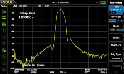
Left: The 300Hz crystal-filter in a recently refurbished RA17L as aligned using the Rigol DSA815-TG
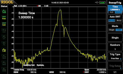
Right: The 100Hz crystal-filter in a recently refurbished RA17L as aligned using the Rigol DSA815-TG
An interesting feature of the DSA815-TG is the inclusion of several measurement programs built into the firmware. These are; an Advanced Measurement Kit, an EMI Filter and Quasi-Peak Detector and a VSWR Measurement kit. All three of these are initially on a trial basis. Unlocking these packages is a tad expensive, but I undestand that these packages produce certified results which can be used as proof of compliance where an end-product is concerned. So perhaps the price is ultimately reasonable.
As a Radio Ham, I was naturally curious about the VSWR Measurement package. Not that I had any intention of purchasing the licence, I was simply interested in what it produced. To me, Return Loss is far more informative, so I have tended to work in dBs Return Loss rather than VSWR. Ironically both are figures derived from calculations.
In order to test out the VSWR Measurement Kit I needed a 4-port VSWR bridge. I could easily build my own, had I the parts. But it proved far less expensive to buy one on-line from a well known market-place. Here's what I got ...
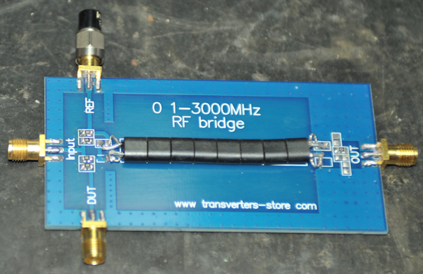
Far-Eastern copy of someone elses hard work ... without the expensive Narda 50-ohm load!
It has to be said, this is a simple, well-proven design ... yet it didn't work! The soldering on the output transformer was dreadful, but not the fault. The truth is, as supplied, this little board was NEVER going to work. See below ...
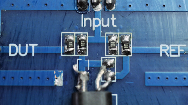
Spot the two missing tracks!
Where 50-ohms is required, two 100-ohm resistors in parallel are employed. Nothing wrong with that. However note the obvious track errors in the photograph above, where two very short, but vital tracks have been left off the artwork. This results in the 100R resistor on the left being in series with one of the ports whilst the second resistor from the right is out of circuit. As a result, this was anything but a balanced 50-ohm bridge.
I contacted the seller, who graciously offered me a 30% refund, which since I was perfectly capable of fixing it myself, I accepted. However, what we have here is a shamelessly bad copy of a Ukrainian product, manufactured in bulk by someone who has absolutely no intention of testing it and probably also has no idea what it actually is!
So back to investigating the VSWR Measurement Kit. A simple aerial might be a first choice for such a test, but I chose a band-pass filter salvaged from a scrapped microwave link. With a 50-ohm termination on one end, I tweaked it for best return-loss on the input at approximaterly 310MHz. Below is a photograph of the test setup. Note that I have removed one of the SMA sockets from the board and replaced it with two 100-ohm resistors in parallel.
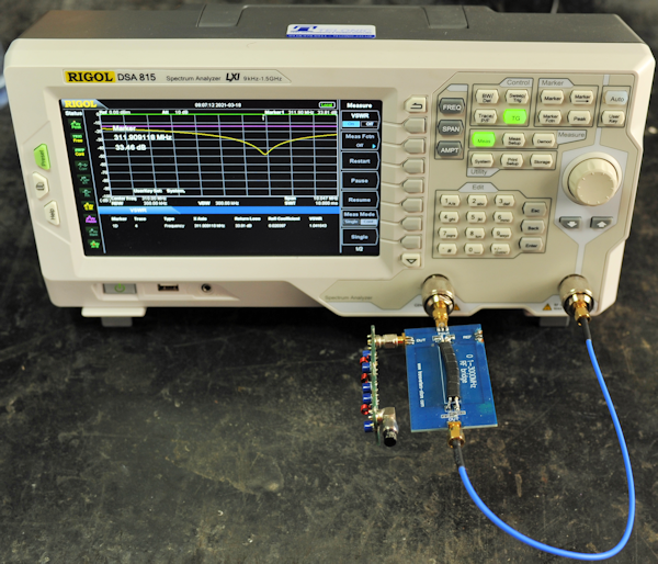
Filter VSWR Test Setup
Details on how to use the VSWR Measurement Kit are in a downloadable PDF and are quite scant. Obviously, you are expected to use one of three available-to-purchase VSWR bridges. Calibration is done with the Test Port either open-circuit or short-circuited, thus providing minimum return-loss. This results in the purple trace in the image below. The yellow trace is produced when the Device Under Test is connected and VSWR is 'pressed'. I haven't been able to work out what the green trace is. The actual VSWR is calculated at the position of the marker, which curiously has to be positioned before the measurement is performed. What I mean is, once you have a measurement in the bottom half of the display, the marker is not re-positionable.
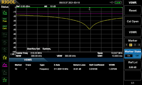
Result of VSWR measurement.
I then carried out the same test as per my usual method ... simply measuring the return loss. I centred the frequency on 310MHz with a span of 10MHz then engaged the tracking generator, leaving the power level at -20dBm. With the filter disconnected I normalised the display and then reduced the Resolution and Video bandwidths to 3KHz. On connecting the filter I then moved Cursor-1 to the dip (greatest return loss).
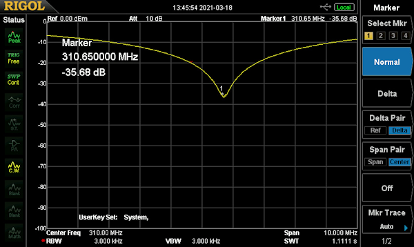
Result of return-loss measurement.
As you can see the results are more or less identical in terms of Return Loss. The difference in frequency is simply because I re-tweaked the filter. My DSA318-TG was ex-demo (I got a really good deal) so the trial period for the three pre-installed measurement kits has now expired, so I can no longer play with the VSWR Measurement Kit. To be honest, I don't really feel inclined to part with just shy of £500 just to unlock it either. But as it stands, the Rigol DSA318-TG is an investment that I will not be regretting. Do I like it? You bet I do!