RA17 MKI Ser. N54
12 minute read
November 2019
A very early RA17, or is it?
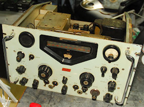
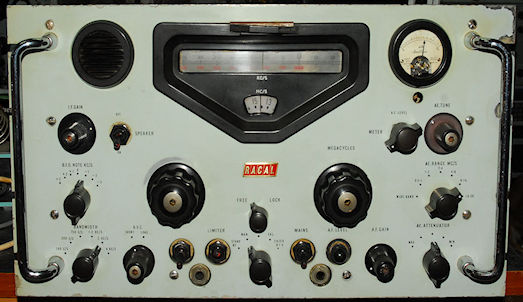
I recently had the opportunity to refurbish a most interesting MKI RA17. As can be seen in the photograph below, the serial plate was missing. In fact it might even be the case that there never was a serial plate. However there was an Admiralty identification plate (see below) which identified the receiver as RA17 Serial number N54, manufactured in 1957. The weight given as 97lbs tells us that it was fitted in its own 19" cabinet.
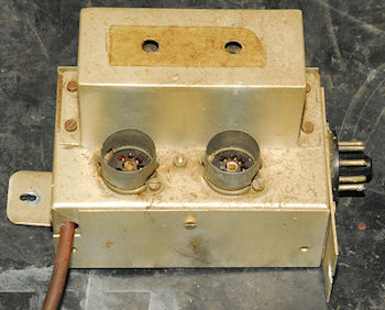
RA17 N54 as received
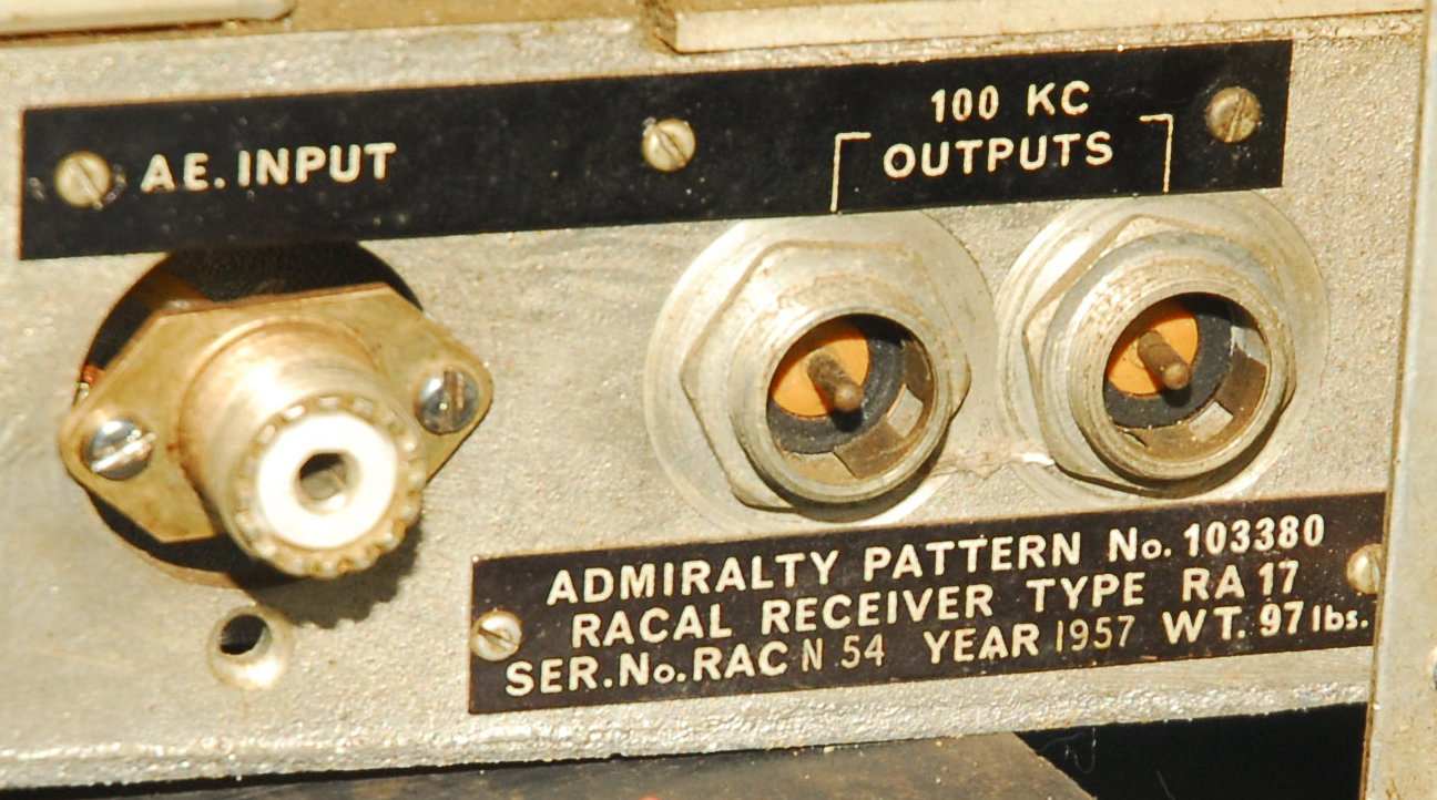
Admiralty label
Having refurbished many RA17s over the last 10 years, there were several things which caught my eye and struck me as unusual. The most obvious being the main tuning knobs which were distinctly different to the type normally found on the front of RA17s etc. I had seen early publicity photographs showing this style of knob but never encountered them personally. The second 'anomaly' was the meter and the associated switch complete with 'chicken-head' knob. The meter itself appeared to be a standard Enest-Turner type 909 but the associated switch bore a resemblance to that fitted to RA117s. The meter scale had also been very carefully hand-altered to include an s-meter scale. The third and possibly most curious anomaly was the presence of what was almost certainly the 1st VFO module from an RA17L although the front-end valve was an E180F. Further investigation revealed that the 2nd VFO module was from an RA17 MKII and the BFO was not original either ... more on that later. As well as the rogue 'chicken-head' knob and the obviously very early tuning knobs, the rest were predominantly the early MKI type, however the Knobs on the preselector were from a much later RA17 i.e. an RA17L.
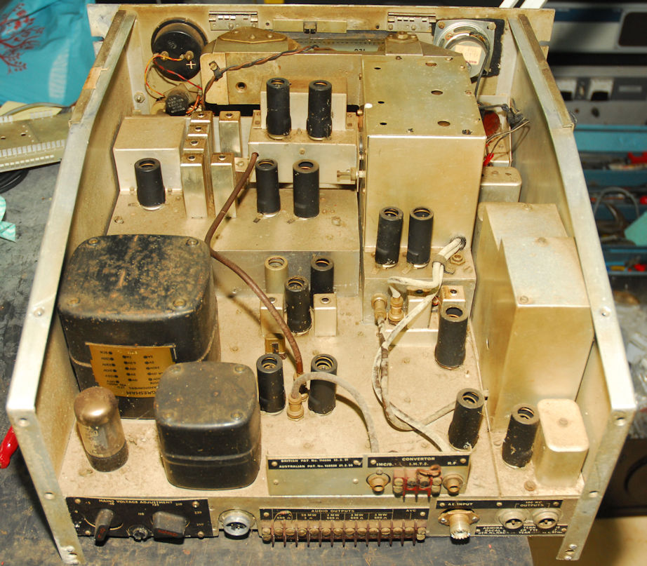
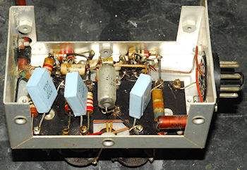
As can be seen, the inside of the receiver was decidely grubby. I honestly thought some of the coax cables were white until I cleaned them and found them all to be brown! The loudspeaker was not original and there was a 3.5mm jack socket on the side gusset panel wired to the loudspeaker. As with all early RA17s, there was no HT+ fuse. There was also no yellow safety warning label over the HT terminals on the rear panel and the Burndept aerial connector had been replaced with an SO-239 connector in a precarious manner.
Since I was going to perform a full electronic refurb, I decided not to even switch it on and began to strip it down to its individual modules. The meter turned out to be a 'repair' and not an original Ernest-Turner movement. It was also sticking. I managed to 'free' it but ultimately it was very problematic and I replaced it with a genuine 'Ernest-Turner' and transfered across the annotated scale plate. The suspect movement turned out to be 500uA too, so it would have not been accurate in s-meter mode.
With the receiver 'broken down', I learned more about the 1st VFO module. This was confirmed as being from an RA17L but in a bold move, the ECC189 Double-Triode had been removed and the unit re-wired to take an E180F Pentode as in the MKI and MKII. This however left it with the wrong pre-selector and since authenticity is what my refurbishment service is all about, I got permission from the owner to fit the correct style of 1st VFO module. Interestingly, there was a label on the inside of the modified VFO dated 21st Novemeber 1989 which I believe identifies Roscar Photoelectronics as the 'bold' modifier. Curiosity led me to do a search for more information and found an archived copy of the North Cornwall Chronicle from 1987 carrying an advert for Roscar Photoelectronics.
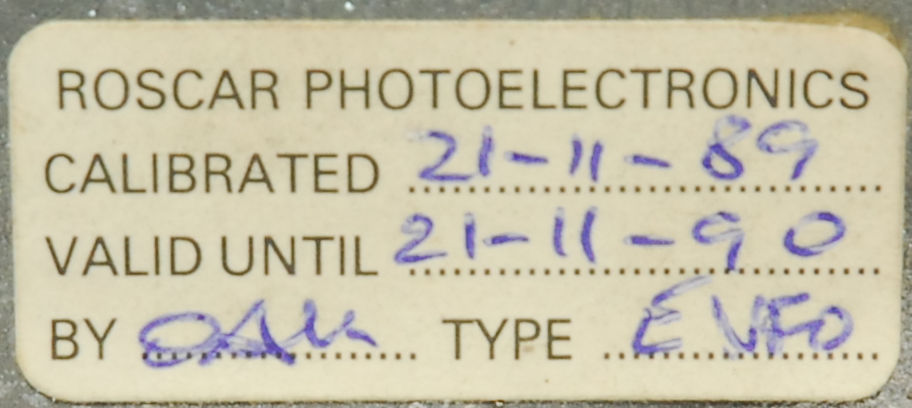
Roscar Photoelectronics label inside VFO
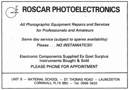
Roscar Photoelectronics advert from 1987
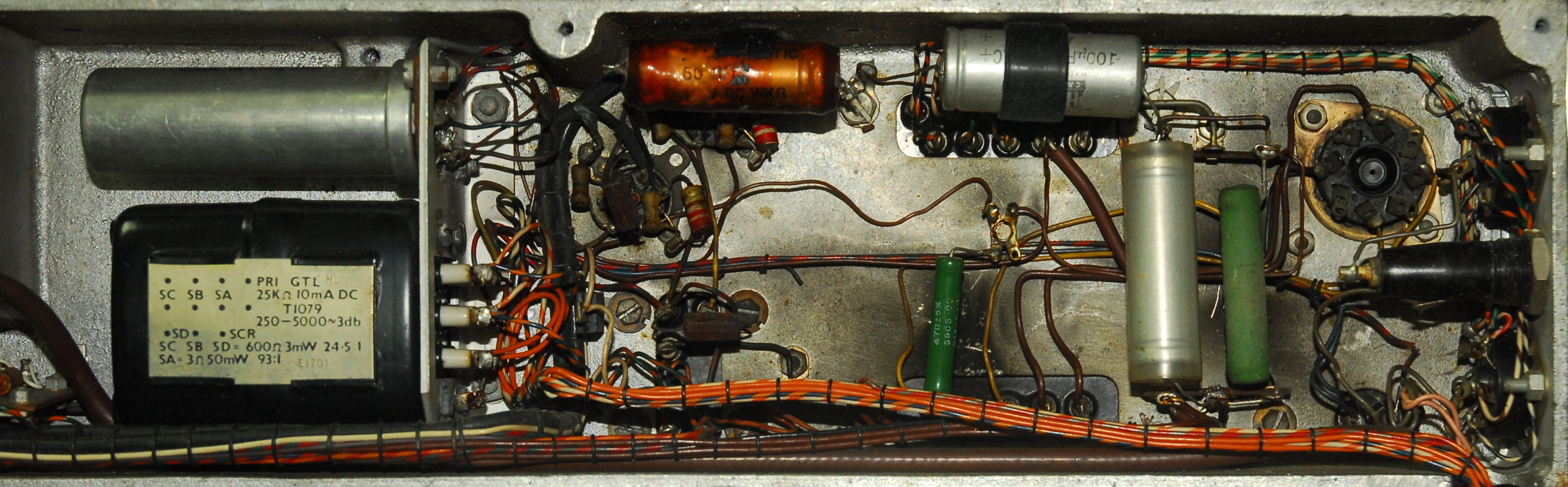
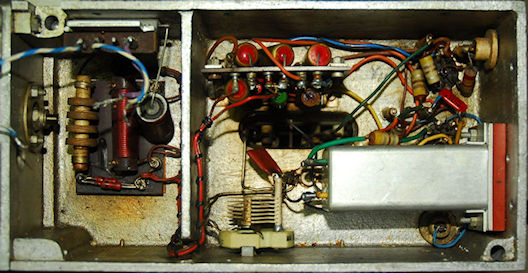
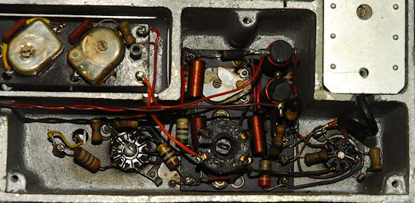
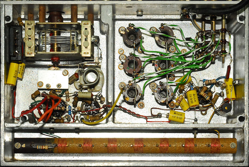
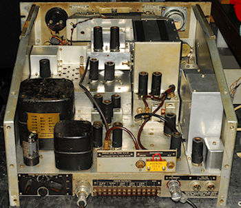
Above: The PSU/Audio compartment prior to refurbishment. Note the lack of 9K or 10K Stand-By load resistor. In fact some early RA17s could not easily be retro-fitted with such a resistor due to a peculiarity of the System Switch whereby when the switch was set to 'Stand By' the wiper is actually pointing at itself.
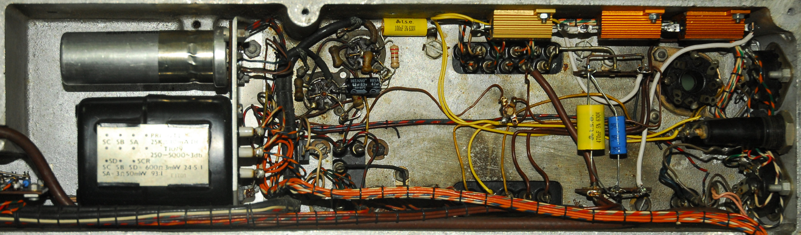
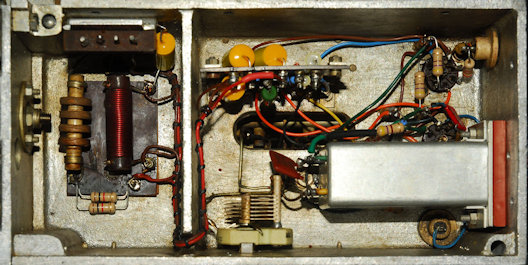
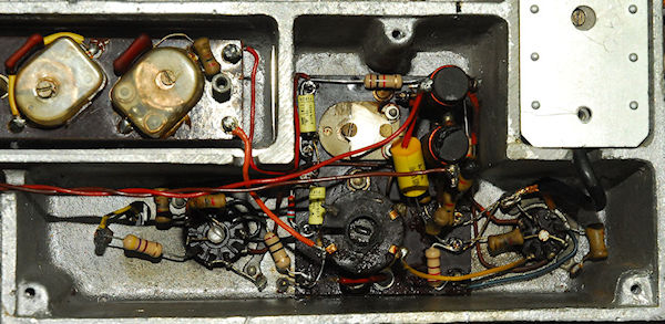
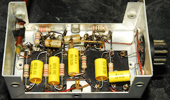
Above: The PSU/Audio compartment refurbished with the addition of the HT+ fuse. The two 'extra' capacitors were removed from the audio stages. These were clearly NOT original as the dodgy nature of the soldering revealed!

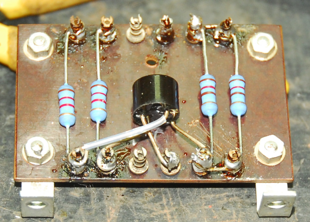
Clearly the meter rectifier had needed replacing, but why isolate one of the 120-ohm resistors? I tidied things up with a new rectifier.
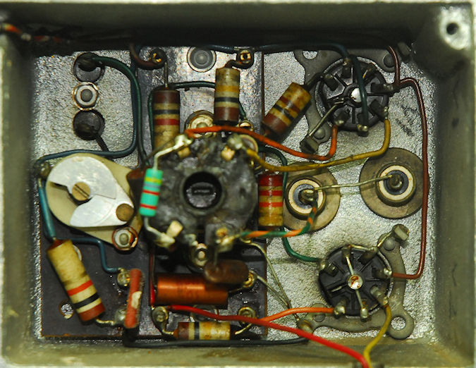
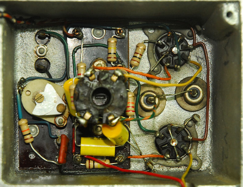
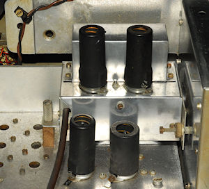
A couple of photographs of the inside of the 2nd VFO: Evidently it had been worked on over the years. The 260pF capacitor in the centre had been moved. It was still electrically in the right place but it should be as close as possible to the inductor in the can. Clearly much of the wiring had been replaced too and the components on the tag-board had also been replaced.
I replaced the ‘new’ wires with correct gauge wire of the correct colour and replaced all the carbon resistors and tubular capacitors. Finally I repositioned the 260pF capacitor.
Before and after shots of the 1MHz oscillator. One of the original resistors had previously been replaced. Most of the other resistors were found to be at least 33% high in value ... This is the norm.
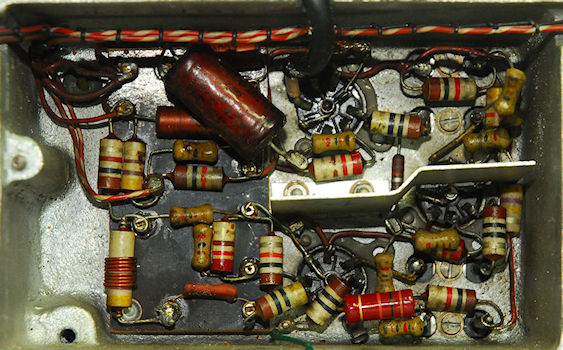
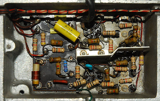
Left: Before and after shots of the Harmonic Mixer and associated 37.5MHz amplifiers. Some of the resistors on the tag-board were found to be over 100% high in value. Elsewhere in this compartment, two resistors had previously been replaced, a 1nF ceramic capacitor of little consequence was missing and an additional 15pF tubular ceramic capacitor had been wired in parallel with one of the tuned circuits. This was worrying since the only reason that I can think for doing this is if the stage fails to tune ... Indicating an open-circuit silvered mica capacitor inside the transformer assembly ... and I was not looking forward to removing the transformer and from the chassis. Fortunately this did not appear to be the case since on retesting this circuit after refurbishment, both tuned circuits tuned perfectly.
Right: Before and after shots of the 2nd Mixer and associated 37.5MHz amplifier. The 1K resistor at the top had been previously replaced. If for any reason a low resistance path appears across the trimmer capacitor, the 1K resistor burns out ... Maybe this was why it had been replaced. Not the easiest of compartments to work on due to the shape.
Above: The replacement 1st VFO in its refurbished state. During test I noticed an intermittent tendency for the VFO to not oscillate below 48MHz (approximately). This intriguing fault was eventually tracked down to a loose solder-tag carrying the wire from the rotor (the body) of the main tuning capacitor to the chassis. This was in effect adding a small capacitance in series and thus lowering the overall capacitance. Something else to check for in future then!
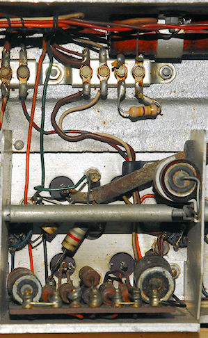
This is interesting; In the photograph on the left; See the orange and green wires and the route that they are taking. Note that they do NOT go via the multi-way tag strip like all the other wires to the IF Strip. This is the s-meter wiring and in conjunction with the 6K8 resistor and the ceramic stand-off, it is identical to that found in the RA117. This circuit can also be found in versions of the RA17 manufactured for the North American market. Such versions being the RA17C and variants. My initial thoughts were that these two wires had been part of the wiring from manufacture, but I have since concluded that since they do NOT go via the tag-strip, the s-meter wiring along with the stand-off and 6K8 resistor must have been added some time later, and done very neatly too! The newer 470K resistor looks like someone's aborted attempt at replicating the front-end AGC circuit in the RA17L etc.
I removed the resistor and cut the green and orange wires in such a way that the ends coming from the wire harness terminated at the two free solder-tags. I then fitted new orange and green wires between the tags and the appropriate points in the IF-strip.

The finished 100KHz IF-strip. The new green and orange wires are clearly visible.
If the IF-strip was original, albeit modified as above, the BFO was NOT. The spares label and the number 818 engraved on it said as much. It had seen significant re-work as the photograph on the left shows, but once it was refurbished and re-installed, the level of drive into the final stage of the IF was too high. This was traced to C215 being 47pF when it should have been 10pF.
Early versions of the RA17 had a different 2nd IF transformer. When this was changed to include a second trimmer capacitor etc., C215 in the BFO was increased from 10pF to 47pF. Ironically I recently worked on another MKI RA17 which exhibited low BFO drive. This was the result of someone changing the BFO to an earlier version with the 10pF capacitor fitted rather than 47pF.
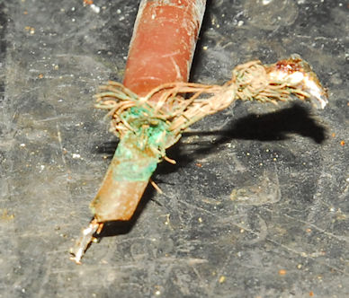
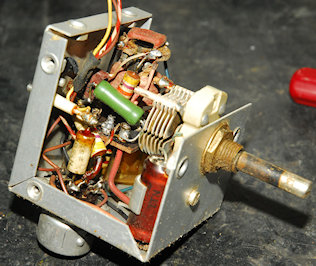
As always, the Calibrator is last to be refurbished ... Usually because I forget about it! This is very likely the original Calibrator which was modified to screw down onto the ex-RA17L 1st VFO. Note the small metal bracket on the left. The early MK1 1st VFOs did not have the Tufnol block for this purpose. Instead the Calibrator had a Tufnol pillar screwed to the underside which merely acted as a foot. There is a hole in the underside of the of this Calibrator where this has been removed. Five of the capacitors had been arbitrarily replaced. The values of four of them were incorrect but this is of little consequence. The coax on the other hand was badly damaged. The inner dielectric was cut right through, exposing the inner conductor and actually shorting to the braid. Fortunately the cable was long enough to cut back, away from the damaged area and re-attach.

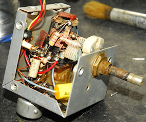
Above: The Calibrator chassis cleaned and the new components fitted. The unit was aligned as per the procedure in the manual with final adjustment carried as part of the receiver. Curiously not all calibrators perform alike ... Some give a relatively weak tone. This one however delivered a good strong healthy tone when enabled.
Left: The refurbished Calibrator re-fitted. The replacement 1st VFO module had been manufactured as a 'spare', bearing the mandatory NATO Stock Number, and was fitted with the Tufnol block. For this purpose, I made a much neater L-bracket for screwing down the Calibrator.
This has been a most interesting RA17 to work on. It is most certainly an original RA17, as the Admiralty label at the rear states, yet it sports an s-meter circuit as supplied in RA17Cs manufactured for North America. So in that case, did it start out as a prototype RA17C? And is that the reason why all the screw-threads are BA as opposed to UNC? As can be seen in the photographs above, it has cleaned up rather well, although the paint on the front panel has seen better days ... but that adds a bit of character. All the knobs are now correct and in the correct place. I had to replace two potentiometers, the main audio gain control and the IF gain control since both proved to be open-circuit at one end. I also had to replace the entire Crystal-Filter module as all the wires to the input transformer were snapped due to failure of the plastic screw used to mount it. Also the detent ball-bearing was missing (the second one I have encountered).