The Racal RA98
4 minute read
This post is part of the series 'Sideband Adapters':
Next post in the series: The Racal RA63
February 2017
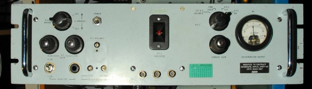
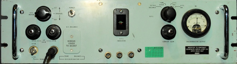
This is an interesting RA98 because the green MOD label indicates that it was used by the Canadian Airforce (RCAF). The RA98C was the North American variant, yet this one started out as an RA98A. The special modifications appear to be the addition of three BNC sockets on the front panel for signal monitoring purposes … probably related to alignment of the adapter.
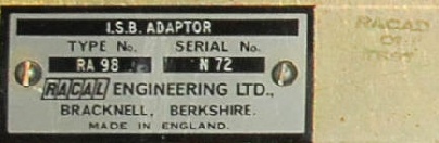
Above: The serial number plate shows that the ‘A’ after the 8 has been inked over and looks like ‘/B’ has been added. Note also the faded ‘stamp’ to the right. Looks like ‘RACAD 01 TEST’. Anyone shed some light on this?
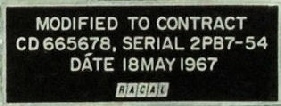
Above: This is the label below the meter. I cannot find any information on what Contract CD665678 relates to. I believe this RA98 was manufactured around 1972, so this is a late modification. Again, anyone shed any light on this?
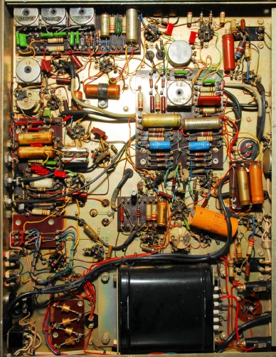
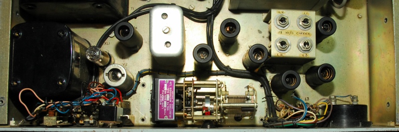
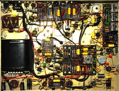
The underside of the RA98 is quite busy. There was evidence of some repair work around the top right in the photograph on the left, with ‘nasty’ soldering. Also, the large orange capacitor just above the mains transformer in the photograph is NOT on the circuit diagram and is much newer than the adapter, suggesting that it was added several years later. It is also of US origin, suggesting that it was added by the user rather than the manufacturer.
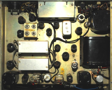
RA98s can be used with any receiver in the RA17 series … i.e. RA17, RA17L or RA117. Since, due to the additional IF in the RA117 resulting in sideband reversal (in relation to the RA17), RA98s have a switch in the centre of the chassis for selecting the receiver type (RA17 or RA117). This RA98 does NOT have said switch but is hard-wired for use with RA117s.
A further difference is that an additional resistor on one of the tag-boards led me to discover that the circuitry which drives the meter and the AFC motor is NOT as per the circuit diagram.
This was going to be an interesting project.
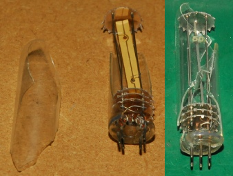
But there was something else: The 18KHz dual-element crystal was missing … No surprises there! I contacted the owner, who apologised and it arrived in the post a few days later … well packed. His description of it being cracked was an understatement.
Initially I thought that I was going to have to make another solid-state 18KHz oscillator like in my RA218. But I quickly realised that although the glass envelope was in two pieces and missing about 25%, the crystal element was intact along with the wires to the pins. I pieced it back together with glue and sticky tape and it worked!!
An interesting feature of the RA98 is the inclusion of motorised mechanically tuned AFC. The photograph below shows the low-torque motor. The crystal next to the PSU choke in the photograph below is not the 18KHz one, but an 89.96KHz crystal. More on that later.
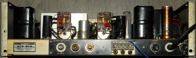
This photograph of the rear of the RA98 shows the re-built 18KHz crystal next to one of the audio output transformers. I managed to find a plastic tube which fitted very snuggly over the valve base thus keeping it safe from further damage. I was surprised to see that Racal chose to use ‘chocolate block’ style connectors for the AGC and Audio outputs. This might have been due to space constraints.
Most of the original Hunts capacitors were physically leaking and a lot of the old-style carbon composite resistors were very high in value and one of the trimmer capacitors in the discriminator had shorting vanes. This had to be carefully repaired since it was non-standard.
Above: The finished RA98. The alignment procedure is a tad ‘grey’ in places, especially when it comes to setting the discriminator. However the AFC works, albeit over a very narrow band, but once set, it copes very well with following a drifting signal. The audio quality of resolved SSB signals is excellent.
But what of the three (non-standard) BNC sockets on the front panel? What purpose do they serve? All have a 1M resistor in series with the centre pin. If we label them from left to right as A, B and C … ‘A’ goes to the cathode of V3 and therefore serves as a monitor point for the internal 118KHz oscillator. ‘B’ goes to pin 2 of V10 and therefore provides a way to monitor the output of the 2nd 18KHz carrier amplifier. And finally, ‘C’ comes from C63 and allows the output of the 18KHz crystal oscillator to be monitored.
But what of the three (non-standard) BNC sockets on the front panel? What purpose do they serve? All have a 1M resistor in series with the centre pin. If we label them from left to right as A, B and C … ‘A’ goes to the cathode of V3 and therefore serves as a monitor point for the internal 118KHz oscillator. ‘B’ goes to pin 2 of V10 and therefore provides a way to monitor the output of the 2nd 18KHz carrier amplifier. And finally, ‘C’ comes from C63 and allows the output of the 18KHz crystal oscillator to be monitored.
Next post in the series: The Racal RA63