Two Adret Signal Generators
10 minute read
This post is part of the series 'Test Equipment':
For many it's the stable signal source that is most difficult to achieve; especially if you want one where the output is both variable in frequency and calibrated. Some of us were lucky. We either had one at work which we could borrow, or we knew someone who had one. Over the years I have owned several signal generators. Some have been more useful than others. Take the Taylor 65B, like the one on the left as an example. I can't remember when, but someone gave me one of these. It actually worked, but everything about it was 'ball-park' ... definitely NOT suitable for anything other than the most rudimentary of tests. I don't remember what happened to mine.
Then I inherited a Marconi TF801D UHF signal generator like the one on the right. Big and cumbersome, and with a propensity to drift; albeit slowly. Ideally the TF801 was intended to be left switched on indefinitely. It was also limited in that it could only generate AM signals. Ultimately, it was too big for my then tiny workshop/shack, so I gave it away. At the time I also had (and still do!) a Gould-Advance SG200 (see below) which, although being no better than the big Marconi in terms of features, was smaller and lighter.
Oddly, at a time when the internet is considered to be the authority on all things, I was unable to find a photograph of an SG200. Thus, I was forced to dig my one out of storage. Quite a curious little signal generator it is too. Clearly the product of the amalgamation of Advance, who had been making signal generators for decades, and Gould Instruments, known for their budget oscilloscopes. Range 'A' covers 0.16MHz to 0.5MHz, yet the scale goes from 16 to 50. Due to the lack of space on the scale, the figures are truncated. It's had a rough life, having fallen off shelves and had things dropped on it. The outer part of the ON/OFF switch is smashed and has to be 'persuaded' to work. But this little 'emergency' signal generator still works and is remarkably stable, although the frequency varies slightly with amplitude.
And then I got my first synthesiser! ... An Adret 740A, dating from around 1986. I had never come across Adret before. However, I have since learned that in the 1980s they (Adret) were represented in the the UK by Racal-Dana, a fact that no doubt explains why this one came to me from Racal. It didn't work though. But who am I to turn down a challenge, especially one that offers free test equipment?
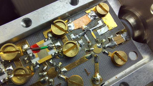
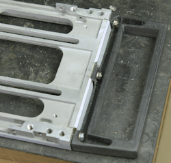
Fortunately the attenuator is an 'electronic' affair, with banks of attenuator elements switched into play by miniature relays. Access was easy after removing the damaged side panel. Close examination revealed a clearly visible 'crack' in the 10dB element closest to the front panel connector. There is an option for the 7100D where the output is protected from up to 1W of reverse power. This one doesn't have that option and someone had clearly transmitted up its output. OUCH! The damaged element had simply been shorted out. I removed the damaged element and managed to buy a suitably rated 10dB element with appropriate orientation. The only problem was it was miniscule and I had to get creative when mounting it. The photograph on the left shows just how much smaller the replacement element is. The green wire attached to the output of the preceding element acts as a matching capacitor. Since my replacement element is so small, such matching is not viable and probably not even required.
With the new element fitted, the 7100D was once again fully functional. It's a shame that the cover caps are missing from three of the knobs, and we can live without the top cover and feet, but hey, I now have two very competent synthesised RF signal generators. I just need to find somewhere to put this one!
A good friend made me a 3D-Printed handle. The montage below shows the fitting process that I came up with before finally painting it.
Next post in the series: Hewlett Packard HP1740A Repair
- Test Equipment for Test Equipment
- Two Adret Signal Generators
- Hewlett Packard HP1740A Repair
- HP 5065A Rubidium Vapour Frequency Standard
- HP 8920A Transceiver Test Set
July 2022
But first ...
You can never have too much test equipment ... It's a fact. You need test equipment to test your test equipment. When I was first licenced back in 1976, you had to list the test equipment that you were going to use to verify the operational integrity of your amateur radio equipment. At the time I was fortunate to work in a college where such equipment was available. Later, when I went to work for Racal, I had an even greater and better range of test gear at my disposal.
Back in the 1970s, much of what we used to get 'on the air' was re-purposed PMR crystal-controlled equipment. There was, off course, off-the-shelf equipment, but many of us schoolboys simply didn't have the money for such luxuries. However, at the time, whether it was ex-PMR or specifically made for the amateur market, it was ultimately maintainable by the user. By that, I mean, these were the days of discrete components. Integrated circuits were still in their infancy ... although, technology was advancing fast, and by the end of the 1970s, even some amateur radio equipment sported 4-bit microprocessors!
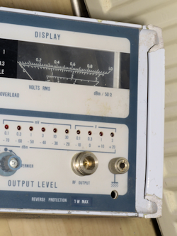
A consequence of the fact that 'our' equipment was, at the time, easily maintainable, there was a prevailing obsession with receiver sensitivity ... and in order to 'tune up' our receivers, we needed test equipment. The minimum test equipment for this is a stable signal source and a means of measuring the level of resolved signal. To give an example, when I am testing the sensitivity of RA17s etc, I use a synthesised signal generator and a calibrated audio power-meter; nothing more.
You can never have too much test equipment ... It's a fact. You need test equipment to test your test equipment. When I was first licenced back in 1976, you had to list the test equipment that you were going to use to verify the operational integrity of your amateur radio equipment. At the time I was fortunate to work in a college where such equipment was available. Later, when I went to work for Racal, I had an even greater and better range of test gear at my disposal.
Back in the 1970s, much of what we used to get 'on the air' was re-purposed PMR crystal-controlled equipment. There was, off course, off-the-shelf equipment, but many of us schoolboys simply didn't have the money for such luxuries. However, at the time, whether it was ex-PMR or specifically made for the amateur market, it was ultimately maintainable by the user. By that, I mean, these were the days of discrete components. Integrated circuits were still in their infancy ... although, technology was advancing fast, and by the end of the 1970s, even some amateur radio equipment sported 4-bit microprocessors!
A consequence of the fact that 'our' equipment was, at the time, easily maintainable, there was a prevailing obsession with receiver sensitivity ... and in order to 'tune up' our receivers, we needed test equipment. The minimum test equipment for this is a stable signal source and a means of measuring the level of resolved signal. To give an example, when I am testing the sensitivity of RA17s etc, I use a synthesised signal generator and a calibrated audio power-meter; nothing more.
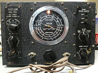
Taylor Model 65B (example).
For many it's the stable signal source that is most difficult to achieve; especially if you want one where the output is both variable in frequency and calibrated. Some of us were lucky. We either had one at work which we could borrow, or we knew someone who had one. Over the years I have owned several signal generators. Some have been more useful than others. Take the Taylor 65B, like the one on the left as an example. I can't remember when, but someone gave me one of these. It actually worked, but everything about it was 'ball-park' ... definitely NOT suitable for anything other than the most rudimentary of tests. I don't remember what happened to mine.
Marconi TF801D (example).
Then I inherited a Marconi TF801D UHF signal generator like the one on the right. Big and cumbersome, and with a propensity to drift; albeit slowly. Ideally the TF801 was intended to be left switched on indefinitely. It was also limited in that it could only generate AM signals. Ultimately, it was too big for my then tiny workshop/shack, so I gave it away. At the time I also had (and still do!) a Gould-Advance SG200 (see below) which, although being no better than the big Marconi in terms of features, was smaller and lighter.
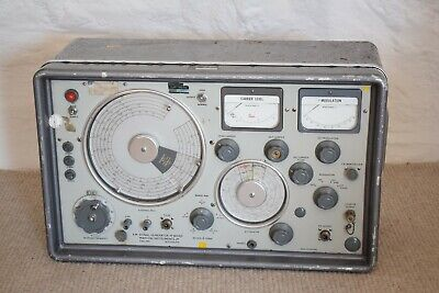
My Gould-Advance SG200.
Oddly, at a time when the internet is considered to be the authority on all things, I was unable to find a photograph of an SG200. Thus, I was forced to dig my one out of storage. Quite a curious little signal generator it is too. Clearly the product of the amalgamation of Advance, who had been making signal generators for decades, and Gould Instruments, known for their budget oscilloscopes. Range 'A' covers 0.16MHz to 0.5MHz, yet the scale goes from 16 to 50. Due to the lack of space on the scale, the figures are truncated. It's had a rough life, having fallen off shelves and had things dropped on it. The outer part of the ON/OFF switch is smashed and has to be 'persuaded' to work. But this little 'emergency' signal generator still works and is remarkably stable, although the frequency varies slightly with amplitude.
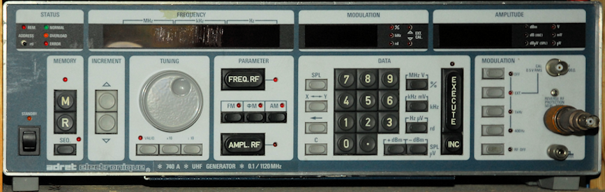
And then I got my first synthesiser! ... An Adret 740A, dating from around 1986. I had never come across Adret before. However, I have since learned that in the 1980s they (Adret) were represented in the the UK by Racal-Dana, a fact that no doubt explains why this one came to me from Racal. It didn't work though. But who am I to turn down a challenge, especially one that offers free test equipment?
The problem was that although, as far as I could immediately tell, everything worked, on closer examination, and it pays to be thorough with these things, something was very wrong with the frequency. First of all there was a constant offset. Secondly at least two of the 'decades' were jumping ... i.e, when the tuning dial was rotated, the frequency would maybe jump several kilohertz or megahertz, depending on which digit was selected. These faults suggested that there were several 'stuck' bits somewhere in the system ... but where? Manuals for Adret equipment are as rare as hen's teeth! And if you do find one, since Adret was a French manufacturer, it is often in French. I had what appeared to be Part Two of the French maintenance manual, but it appeared to be incomplete. I had some schematics and board layouts, but not all. Secondly there were no procedures or circuit descriptions ... presumably these were in Part One?
I did manage to find a more comprehensive manual for the 740's little brother, the 730, and this turned out to be more help than expected. I anticipated that there would be some similarity. I identified the boards that I didn't have schematics for and found that these were very similar to boards in the 720. This enabled me to track down a couple of duff logic gates. A frustrating feature of the 740 is that Adret chose to use custom edge-connectors for the boards. The only way to get around this was to identify which parts of the circuit I wanted to monitor, then solder suitably long, but not too long, wires onto the board, then plug it back in. Although a tad time consuming, this method paid off.
The Adret 740 (and presumable the 730 too) suffers from a similar problem to that found in the Racal RA1792. The 740 has a non-volatile memory on the Processor board that is maintained by a Nickel-Cadmium battery. As with many original RA1792 processor boards, the on-board battery in my 740 had deteriorated and spilled its contents all over a good part of the board. The corrosive nature of the spill naturally resulted in several dissolved tracks and more than a few completely destroyed via-holes. Fortunately the board is only double-sided, and not multi-layer. As well as by-passing badly corroded lengths of track, and popping tiny wires into damaged via-holes, I also found that even a few solder joints had been compromised. The process of identifying all such failures continued for some time, even after I had got the 740 working. For a while there was the odd occasion when simply moving it across the bench would cause it to malfunction and a gentle prod of the processor board would 'fix' it.
Eventually I did manage to collect information on all the PCBs in the 740 and I even found someone who offered to lend me his custom-made card extender, which made diagnosing many of the faults so much easier. I can now say that My Adret 740 now travels well. By that I mean it no longer stops working if it is moved. The only issue with it these days is the mains-switch which occasionally doesn't quite 'connect'.
Then last year (2021), I was offered a faulty Adret 7100D and I immediately thought 'Spare Parts!' ... especially these custom connectors. However, The 7100D which dates from 1983 doesn't use custom edge-connectors. Indeed, it didn't work ... the RF output was hopping about all over the place. It had a sheered off handle which I was informed was the direct result of a courier dropping it. It was also missing the top cover and feet. But at least it powered up and did something.
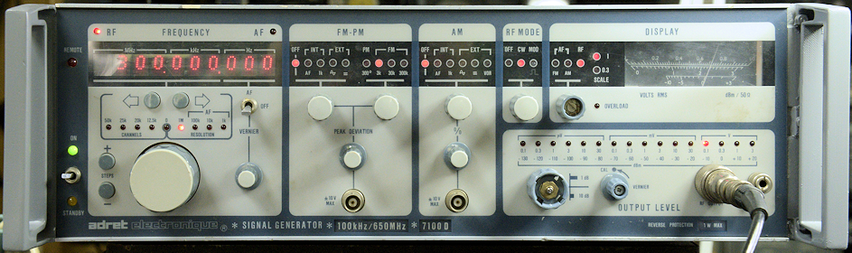 Pre-dating the 740 by three years, the technology is not too dissimilar. The rack of PCBs is at 90 degrees to that in the 740 but the huge RF module looks familiar. The PSU looks proprietary and there is no non-volatile memory. The main difference is the obvious lack of buttons to press. Also, where the 740 covers 100KHz to 1120MHz; the range of the 7100D is 100KHz to 650MHz, although I have found that it does go down to 80KHz.
Since it had no top cover, I found myself staring at the rack of PCBs and noticed that the PCBs were numbered 1 to 6, and noticed that the board carrying the number 6 was actually in slot 8. I switched it off and moved the board into slot 6 and switched it back on. Hey Presto! The frequency hopping had stopped. Well, that was easy. I thought. But let's not get ahead of ourselves. Let's run some tests. Everything was working with the exception of the output attenuator which appeared to have a dead element in it somewhere. Repairing it turned out to be much easier than anticipated.
I did manage to find a more comprehensive manual for the 740's little brother, the 730, and this turned out to be more help than expected. I anticipated that there would be some similarity. I identified the boards that I didn't have schematics for and found that these were very similar to boards in the 720. This enabled me to track down a couple of duff logic gates. A frustrating feature of the 740 is that Adret chose to use custom edge-connectors for the boards. The only way to get around this was to identify which parts of the circuit I wanted to monitor, then solder suitably long, but not too long, wires onto the board, then plug it back in. Although a tad time consuming, this method paid off.
The Adret 740 (and presumable the 730 too) suffers from a similar problem to that found in the Racal RA1792. The 740 has a non-volatile memory on the Processor board that is maintained by a Nickel-Cadmium battery. As with many original RA1792 processor boards, the on-board battery in my 740 had deteriorated and spilled its contents all over a good part of the board. The corrosive nature of the spill naturally resulted in several dissolved tracks and more than a few completely destroyed via-holes. Fortunately the board is only double-sided, and not multi-layer. As well as by-passing badly corroded lengths of track, and popping tiny wires into damaged via-holes, I also found that even a few solder joints had been compromised. The process of identifying all such failures continued for some time, even after I had got the 740 working. For a while there was the odd occasion when simply moving it across the bench would cause it to malfunction and a gentle prod of the processor board would 'fix' it.
Eventually I did manage to collect information on all the PCBs in the 740 and I even found someone who offered to lend me his custom-made card extender, which made diagnosing many of the faults so much easier. I can now say that My Adret 740 now travels well. By that I mean it no longer stops working if it is moved. The only issue with it these days is the mains-switch which occasionally doesn't quite 'connect'.
Then last year (2021), I was offered a faulty Adret 7100D and I immediately thought 'Spare Parts!' ... especially these custom connectors. However, The 7100D which dates from 1983 doesn't use custom edge-connectors. Indeed, it didn't work ... the RF output was hopping about all over the place. It had a sheered off handle which I was informed was the direct result of a courier dropping it. It was also missing the top cover and feet. But at least it powered up and did something.
Since it had no top cover, I found myself staring at the rack of PCBs and noticed that the PCBs were numbered 1 to 6, and noticed that the board carrying the number 6 was actually in slot 8. I switched it off and moved the board into slot 6 and switched it back on. Hey Presto! The frequency hopping had stopped. Well, that was easy. I thought. But let's not get ahead of ourselves. Let's run some tests. Everything was working with the exception of the output attenuator which appeared to have a dead element in it somewhere. Repairing it turned out to be much easier than anticipated.
New attenuator element.
Fortunately the attenuator is an 'electronic' affair, with banks of attenuator elements switched into play by miniature relays. Access was easy after removing the damaged side panel. Close examination revealed a clearly visible 'crack' in the 10dB element closest to the front panel connector. There is an option for the 7100D where the output is protected from up to 1W of reverse power. This one doesn't have that option and someone had clearly transmitted up its output. OUCH! The damaged element had simply been shorted out. I removed the damaged element and managed to buy a suitably rated 10dB element with appropriate orientation. The only problem was it was miniscule and I had to get creative when mounting it. The photograph on the left shows just how much smaller the replacement element is. The green wire attached to the output of the preceding element acts as a matching capacitor. Since my replacement element is so small, such matching is not viable and probably not even required.
With the new element fitted, the 7100D was once again fully functional. It's a shame that the cover caps are missing from three of the knobs, and we can live without the top cover and feet, but hey, I now have two very competent synthesised RF signal generators. I just need to find somewhere to put this one!
A good friend made me a 3D-Printed handle. The montage below shows the fitting process that I came up with before finally painting it.
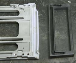
Damaged Handle.
3D-Printed handle, as supplied.
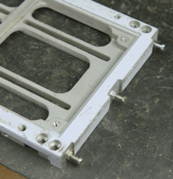
Three M3 screws are fitted into tapped holes before their heads are sawn off.
New Handle!
Next post in the series: Hewlett Packard HP1740A Repair