Test Equipment for Test Equipment
19 minute read
This post is part of the series 'Test Equipment':
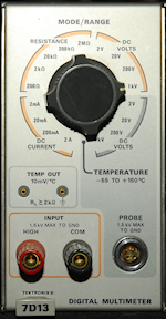
Left: 7D13 - A 3-and-a-half digit Digital Multimeter with CRT readout for 7000-series mainframes. Can also be used to measure temperature with P6058 probe (which I don't have).
The bandwidth and speed of the various plug-ins is wholly dependent on the particular 7000-series mainframe used. To achieve maximum bandwidth, ideally 7800 or 7900 mainframes should be used.
For full details on vintage Tektronix hardware go to TekWiki
Receiver sensitivity is all about signal-to-noise ratio. I have heard some truly weird methods that people have used to try to ascertain the sensitivity of their receivers. Many of these methods actually require your ears to be calibrated ... which they're not!
The simplest way to check a receiver's sensitivity is like this ... Let's check a Racal RA17 at 1.5MHz for 1uV at 3KHz IF B/W ...
Receiver initial settings:
RF/IF Gain to Max
AGC (AVC) OFF.
BFO ON.
RF attenuator to minimum.
IF Bandwidth to 3KHz.
Set the meter to indicate RF level.
Method:
Set the RF signal source to 1.5MHz CW, and set the output level to 1uV emf.
Connect the signal source to the receiver's input and tune the receiver (e.g. RA17) for maximum indication on the meter, adjusting the preselector accordingly.
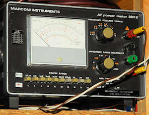
Connect the external audio output to an audio wattmeter like the Marconi 893B and carefully adjust the BFO for maximum audio level on the wattmeter.
Turn the volume up full. Switch off the receiver's internal loudspeaker if present. It is important that the wattmeter impedance is set to match the expected external speaker impedance.
In the case of the RA17/RA17L, use the external 3-ohm output. This should give over 300mW into the wattmeter. If you can't achieve that, turn the volume down and go for a level that exceeds 100mW. The actual level is not too important.
Now back the RF/IF gain control off until the reading on the wattmeter is 300mW (or 100mW), then make a final adjustment so that the needle on the wattmeter aligns with 0dB. This is your initial reading.
Now switch off the RF output from the signal source, or disconnect the signal source from the receiver and terminate the aerial connector appropriately.
Verify that the reading on the wattmeter drops significantly.
Now measure the receiver audio power into the wattmeter. For a factory-spec RA17 you should expect a level something like 20dB down on your initial measurement.
This is the receiver's sensitivity in terms of signal-to-noise ratio, or more correctly signal plus noise-to-noise.
Above: Two very versatile instruments. Dating from the early 1960s, the Marconi TF-1041B is actually more than just a voltmeter. It is also an RF rms Voltmeter offering an almost flat response from 1KHz up to 500MHz but is useable up to 1.5GHz. It can also measure resistances from 0.02 Ohms to 500 Megohms. I like how it is described as a Vacuum Tube Voltmeter. I wonder if this was for the North American market?
I picked up the LAV-191 when Mitsubishi closed their VCR manufacturing facility down the road some time ago. Since my Adret 740A won't 'go' below 100KHz, the LAV-191 comes in handy for chasing faults in the 100KHz IF strip in RA17s etc. The rms Voltmeter option is extremely useful since the input impedance is 10 Megohms, whereas the Racal-Dana 9301A is either 100K or 50R.
I count myself extremely fortunate in having these two AVO valve testers, or Valve Characteristic Meters. Each caters for several valve bases that the other doesn't, hence the reason for keeping the MKII when I acquired the VCM-163. I have heard of people who have extended the 'repertoir' of one valve tester by simply connecting a multiway cable between it and another tester. I admit that this sounds really innovative and a clever way to include the bases of one tester with another. However after some thought on the matter, I'm not sure that linking two testers in this way is actually a good idea. AVO make it very clear that the wiring layout under the top of their testers is layed out in such a way as to minimise the risk of parasitic oscillation. Thus linking two testers via the test sockets sounds to me like it might actually increase the risk of oscillation. My VCM-163 had previously been linked to a MK4 AVO VCM in this way and when I received it I found it to have several burned out resistors inside. I can't prove it, but I suspect that the resistors were burned out as a result of induced parasitic oscillations.
As a refurbisher of vintage military radios, I have come to see such intruments as an absolute necessity. As well as identifying serious faults, over the years, I have found that replacing valves with the slightest indication of inter-electrode leakage can improve the over-all signal-to-noise figure.
I built my SDR-Kits VNWA V2.6 from a kit way back in 2010! As a 2-port Vector Network Analyzer, it is 'good' up to 1.3GHz. Although I have done a significant amount of microwave home-contruction, right up to 24GHz, I actually invested in the DG8SAQ VNWA primarily to enable me to align the 40MHz Band-Pass filter in the RA17 series of receivers. Although this is a 50-ohm device, and the 40MHz filter is definitely NOT 50-ohm, I have not had any problems and the results that I have achieved speak for themselves.
On the right we have my newly acquired nanoVNA V2 from OwOComm. This is a truly remarkable little instrument. Not only is it smaller than the DG8SAQ VNWA but it incorporates its own colour 'touch-screen', is 'good' up to 3GHz and useable up to 4GHz. Although it can be controlled via the built-in micro-USB port, it is otherwise fully self-contained. How technology has changed in 10 years! Back in the late 80s the 'Holy-Grail' of RF network analysis was the HP8510 which still required an external sweep oscillator ... and before that it was the HP8409 which involved a whole rack of equipment, all controlled by an HP9826A computer. I shall leave the description of both of these setups for another blog entry.
On the right is a plot on the nanoVNA V2 of a GSM/UMTS multiband dipole between 500MHz and 3GHz.
This morning I tested my own microwave yagis using the nanoVNA V2. Examining the frequency response of ANY antenna down a length of coax is always going to be compromised by the VSWR of the transmission-line itself, however it did turn out to be an interesting exercise with enlightening results.
My 23cm 35-ele Tonna appeared to resonate at 1290MHz whilst my 13cm 25-ele Tonna was resonant at 2.3GHz and my home-brew 48-ele Quad-Loop yagi for 9cm was spot-on at 3.4GHz!
Left: I almost forgot about my trusty Systron-Donner Spectrum Analyser (10MHz to 12.4GHz).
Here it is displaying a 450MHz 1mW signal from the Adret 740A.
Note the re-labelled 'reversed' replacement input attenuator.
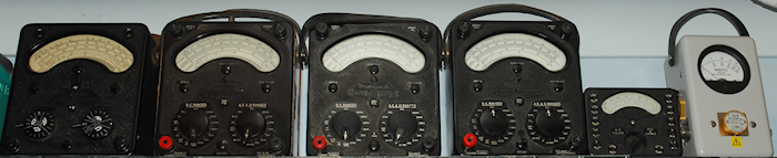 Finally, where would we be without the legendary AVO-Meter? A few years back I went through a phase of buying AVOs. The idea was to get a working AVO and maybe buy another to use as a source of spares. I ended up with (left to right) a lovely Model 7 and three Model 8s one of which is the Panclimatic version and an Avo-Minor, all of which work. Looks like my Bird Thru-Line Power Meter snuck in on the end there.
Next post in the series: Two Adret Signal Generators
- Test Equipment for Test Equipment
- Two Adret Signal Generators
- Hewlett Packard HP1740A Repair
- HP 5065A Rubidium Vapour Frequency Standard
- HP 8920A Transceiver Test Set
October 2020
I started out to write a piece about repairing a cute little Hewlett-Packard bench power-supply. However, the deeper I dug (looking for information), the more I was convinced that I should really talk about test equipment.
It came to me the other day that as companies, there were similarities between Racal and Hewlett-Packard. Both became giants in their own specific field; Communications and Test Equipment respectively. Both were founded by two men. The name Racal is derived from the names of two former Plessey engineers, Ray Brown and Calder Cunningham, who founded Racal in 1950. Hewlett-Packard, rather less subtly, was founded by Bill Hewlett and Dave Packard who met whilst at Stanford University in the 1930s and on occasion worked closely with Fred Terman, who is widely credited (together with William Shockley) as being the father of Silicon Valley. I have a First Edition (albeit 16th impression) copy of Terman’s book, ‘Fundamentals of Radio’.
Both companies excelled in their (initial) field at a time when advances in electronics were thick and fast. In the 50s and 60s Racal produced a seemingly endless range of adapters and enhancements for the RA17 series of communications receivers. Whilst right from its incorporation in 1947, HP was responsible for an ever-growing range of test equipment who’s build quality was legendary.
As well as my collection of Racal HF receivers, I also have a growing collection of Test Equipment. Someone once joked that if you have test equipment, you need more test equipment to maintain it. At first it sounds funny, but in reality its actually very true.
Last week a friend informed me that he was having a clear-out and asked if I was interested in some test equipment. The list included a Sweep Oscillator, a couple of Voltmeters, a small bench Power Supply and a couple of Pulse Generators. The Sweep Oscillator, Voltmeters and Power Supply were all Hewlett-Packard ... no model numbers given ... but its HP test kit! ... and you can't have too much of that, so I said yes please!
Today I came to the conclusion that I can even divide my collection of test equipment up by manufacturer ... Hewlett-Packard, Racal-Dana and Tektronix ... and a few others. My Hewlett-Packard collection was about to get larger.
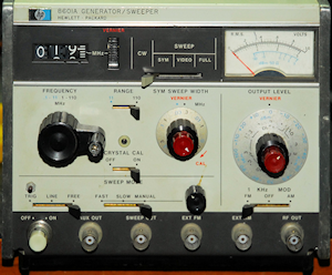
The Sweep Oscillator, I recognised immediately; an HP8601A. The college where I worked when I left school had one, although in three years, I never saw it being used ... perhaps because at 110MHz, its upper frequency was rather low. As a new Radio Ham in 1976, I myself was somewhat disappointed since back then as a newly licenced Class-B operator, the lowest frequency that I was allowed to operate on was 144MHz. So the 8601A was dismissed as of little use ... at the time.
I powered it up and found that it worked, albeit a bit ‘noisy’ on account of a couple of dirty switches. This issue was resolved by several carefully aimed squirts of De-Oxit. At first I thought the internal FM modulator was inoperative until I connected it to my Racal-Dana 9008 Modulation Meter. It was indeed working. On the other hand, massive levels of Frequency Modulation can be achieved when using an External modulation source. In retrospect, this is very obvious when looking at the schematic. The vernier knob on the output attenuator was damaged, so I was going to have to find a replacement .
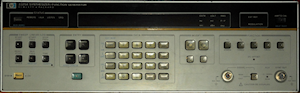
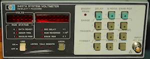
The two Voltmeters turned out to be what HP called System Voltmeters. The HP3437A was clearly designed to be part of a larger network of equipment and isn’t really suitable for bench use. It was very likely designed as a means of making and recording precisely timed high-speed voltage measurements.
Whilst one of the 3437s had suffered physical damage to the front panel, internally it was in better condition than the other. The latter had also had the front panel Triax connector (sometimes called a Twinax connector) replaced with a standard BNC connector. I swapped the front panels and replaced the BNC with a Triax connector. I haven’t tested the trigger functions yet, but as a voltmeter it works.
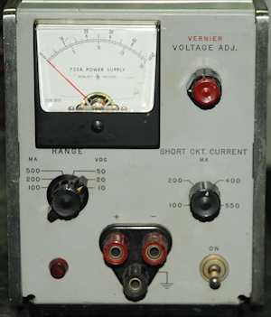
The small bench power-supply turned out to be an HP723A (0-40V @ 500mA) with a smashed ‘Course’ Output-Voltage knob. It was also faulty in that the output wouldn’t go above 27V. Interestingly this is one piece of HP kit for which a manual is not freely available to download. As a result there are several reputable document suppliers who are happy to sell you a copy. I also found at least two decidedly dodgy websites keen to cash in on the fact that the manual is not out there in the public domain.
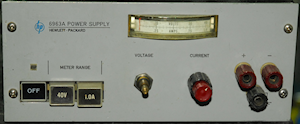
This little power supply and a slightly larger one (HP6963A) that I was given some time ago are apparently originally by Harrison Labs, who HP went on to acquire. My 6963A is shockingly dirty inside, looking like it was sprayed with dirty water at some point. For this reason, I have NO intention of ever switching it on! Fortunately both PSUs use the same knobs, so I was able to replace the smashed knob on the 723A with one from the 6963A.
After working out most of the 723A’s schematic, I was able to compare it with that of an HP721A (also by Harrison Labs). This then enabled me to re-draw what I had drawn to some degree and then figure out which of the germanium PNP transistors had failed ... a 2N1300 in the voltage reference circuit.
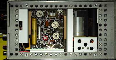
Left: The side panel can be removed to give access to the PCB. The faulty transistor is the one with the red heat-sink. I replaced it with a TO-39 2N2905A. Silicon, not Germanium, but it does the job.
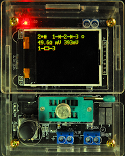
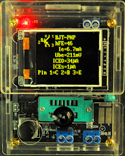
I was curious as to what was going on with the duff 2N1300. I wasn't even sure that it was the original transistor since it was not 'company-coded'. Hewlett-Packard have a long history of identifying their semiconductors with their own HP-specific part-numbers, and this one wasn't. I checked it with the diode feature on my multimeter and indeed the Base-Emitter and Base-Collector junctions appeared OK. But with the meter between Emitter and Collector it was a low-value resistor!
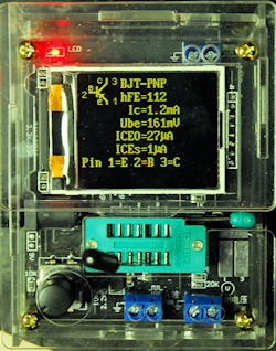
Quite fortuitously I had just assembled a low-cost Chinese-made Transistor Tester, so I popped the 2N1300 into the Zif-Socket and pressed the button. Sure enough, it was detected as a pair of diodes and a low value resistor. Just to prove that the tester 'knew' what it was doing I also tested an unused OC44 and a truly vintage semiconductor, an XB102. The results speak for themselves. Exactly what has happened to the 2N1300, I cannot say, other than it no longer functions as a transistor.
 The little HP723A now works beautifully. It pre-dates the adoption of the now standardised IEC Mains Connector and thus sports an oval 3-pin chassis-plug (as on my Systron-Donner Spectrum Analyser) sometimes referred to as a NEMA-Connector or Belden-Connector. I came up with a simple solution for this.
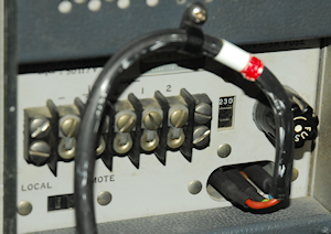
To get around the fact that I didn't have a NEMA-fitted mains-lead, I made my own , sort of. I took three round steel pillars which fitted nicely over each of the three pins. I then took some thin copper tape and cut it into strips about 5mm longer than a pillar. I then rolled each strip once around a small screwdriver whose shaft just fitted through the pillar. I then carefully pushed each rolled-up copper tape into each pillar and tested them for snugness on the connector pins. It worked! The copper tape gives just the right amount of friction and contact. I then soldered appropriate wires of a mains cord into exposed copper solder-spils then finally shrouded each pillar/socket in heat-shrink sleeving.
I also have another oscilloscope, an HP1740A, however the traces have noise on them. One day I may get it out of the attic and attempt to fix it. I do like the 1745A. It is very easy to use and the four rubber feet at the rear make it ideal for 'off the bench' work where it sits nicely on the floor, provided you have a right-angled IEC lead. One unfortunate thing though is that the rubber that these feet are made from deteriorates over time. They become brittle and break apart. I have salvaged the rear feet from my 1740A to replace those on the 1745A, and these too are now breaking apart. For bench work, I use a Textronix 7600 series 'scope.
It came to me the other day that as companies, there were similarities between Racal and Hewlett-Packard. Both became giants in their own specific field; Communications and Test Equipment respectively. Both were founded by two men. The name Racal is derived from the names of two former Plessey engineers, Ray Brown and Calder Cunningham, who founded Racal in 1950. Hewlett-Packard, rather less subtly, was founded by Bill Hewlett and Dave Packard who met whilst at Stanford University in the 1930s and on occasion worked closely with Fred Terman, who is widely credited (together with William Shockley) as being the father of Silicon Valley. I have a First Edition (albeit 16th impression) copy of Terman’s book, ‘Fundamentals of Radio’.
Both companies excelled in their (initial) field at a time when advances in electronics were thick and fast. In the 50s and 60s Racal produced a seemingly endless range of adapters and enhancements for the RA17 series of communications receivers. Whilst right from its incorporation in 1947, HP was responsible for an ever-growing range of test equipment who’s build quality was legendary.
As well as my collection of Racal HF receivers, I also have a growing collection of Test Equipment. Someone once joked that if you have test equipment, you need more test equipment to maintain it. At first it sounds funny, but in reality its actually very true.
Last week a friend informed me that he was having a clear-out and asked if I was interested in some test equipment. The list included a Sweep Oscillator, a couple of Voltmeters, a small bench Power Supply and a couple of Pulse Generators. The Sweep Oscillator, Voltmeters and Power Supply were all Hewlett-Packard ... no model numbers given ... but its HP test kit! ... and you can't have too much of that, so I said yes please!
Today I came to the conclusion that I can even divide my collection of test equipment up by manufacturer ... Hewlett-Packard, Racal-Dana and Tektronix ... and a few others. My Hewlett-Packard collection was about to get larger.
The Sweep Oscillator, I recognised immediately; an HP8601A. The college where I worked when I left school had one, although in three years, I never saw it being used ... perhaps because at 110MHz, its upper frequency was rather low. As a new Radio Ham in 1976, I myself was somewhat disappointed since back then as a newly licenced Class-B operator, the lowest frequency that I was allowed to operate on was 144MHz. So the 8601A was dismissed as of little use ... at the time.
I powered it up and found that it worked, albeit a bit ‘noisy’ on account of a couple of dirty switches. This issue was resolved by several carefully aimed squirts of De-Oxit. At first I thought the internal FM modulator was inoperative until I connected it to my Racal-Dana 9008 Modulation Meter. It was indeed working. On the other hand, massive levels of Frequency Modulation can be achieved when using an External modulation source. In retrospect, this is very obvious when looking at the schematic. The vernier knob on the output attenuator was damaged, so I was going to have to find a replacement .
The two Voltmeters turned out to be what HP called System Voltmeters. The HP3437A was clearly designed to be part of a larger network of equipment and isn’t really suitable for bench use. It was very likely designed as a means of making and recording precisely timed high-speed voltage measurements.
Whilst one of the 3437s had suffered physical damage to the front panel, internally it was in better condition than the other. The latter had also had the front panel Triax connector (sometimes called a Twinax connector) replaced with a standard BNC connector. I swapped the front panels and replaced the BNC with a Triax connector. I haven’t tested the trigger functions yet, but as a voltmeter it works.
The small bench power-supply turned out to be an HP723A (0-40V @ 500mA) with a smashed ‘Course’ Output-Voltage knob. It was also faulty in that the output wouldn’t go above 27V. Interestingly this is one piece of HP kit for which a manual is not freely available to download. As a result there are several reputable document suppliers who are happy to sell you a copy. I also found at least two decidedly dodgy websites keen to cash in on the fact that the manual is not out there in the public domain.
This little power supply and a slightly larger one (HP6963A) that I was given some time ago are apparently originally by Harrison Labs, who HP went on to acquire. My 6963A is shockingly dirty inside, looking like it was sprayed with dirty water at some point. For this reason, I have NO intention of ever switching it on! Fortunately both PSUs use the same knobs, so I was able to replace the smashed knob on the 723A with one from the 6963A.
After working out most of the 723A’s schematic, I was able to compare it with that of an HP721A (also by Harrison Labs). This then enabled me to re-draw what I had drawn to some degree and then figure out which of the germanium PNP transistors had failed ... a 2N1300 in the voltage reference circuit.
Left: The side panel can be removed to give access to the PCB. The faulty transistor is the one with the red heat-sink. I replaced it with a TO-39 2N2905A. Silicon, not Germanium, but it does the job.
I was curious as to what was going on with the duff 2N1300. I wasn't even sure that it was the original transistor since it was not 'company-coded'. Hewlett-Packard have a long history of identifying their semiconductors with their own HP-specific part-numbers, and this one wasn't. I checked it with the diode feature on my multimeter and indeed the Base-Emitter and Base-Collector junctions appeared OK. But with the meter between Emitter and Collector it was a low-value resistor!
Quite fortuitously I had just assembled a low-cost Chinese-made Transistor Tester, so I popped the 2N1300 into the Zif-Socket and pressed the button. Sure enough, it was detected as a pair of diodes and a low value resistor. Just to prove that the tester 'knew' what it was doing I also tested an unused OC44 and a truly vintage semiconductor, an XB102. The results speak for themselves. Exactly what has happened to the 2N1300, I cannot say, other than it no longer functions as a transistor.
Faulty 2N1300
OC44
A genuine antique ...
an XB102
an XB102
To get around the fact that I didn't have a NEMA-fitted mains-lead, I made my own , sort of. I took three round steel pillars which fitted nicely over each of the three pins. I then took some thin copper tape and cut it into strips about 5mm longer than a pillar. I then rolled each strip once around a small screwdriver whose shaft just fitted through the pillar. I then carefully pushed each rolled-up copper tape into each pillar and tested them for snugness on the connector pins. It worked! The copper tape gives just the right amount of friction and contact. I then soldered appropriate wires of a mains cord into exposed copper solder-spils then finally shrouded each pillar/socket in heat-shrink sleeving.
My Hewlett-Packard test equipment
HP1745A - 100MHz 2-CH Analogue Oscilloscope
HP3325A - 20MHz Synthesizer/Function Generator
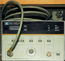
HP436A - Power Meter with HP8481A Power Sensor
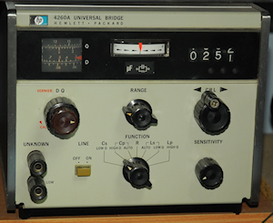
HP4260A - Universal Bridge
HP8601A - Generator/Sweeper
HP3437A - System Voltmeter
I must find a use for this!
I must find a use for this!
HP723A - Bench Power Supply
0 - 40V at 500mA
0 - 40V at 500mA
HP6253A - Dual DC Power Supply
0 - 30V at 3A
When I got this, the RH meter bezel was missing. I fashioned one out of acrylic which I then sprayed grey. Both the Mains indicators were u/s, and were subsequently replaced.
A nice 19" rack-mounting PSU.
0 - 30V at 3A
When I got this, the RH meter bezel was missing. I fashioned one out of acrylic which I then sprayed grey. Both the Mains indicators were u/s, and were subsequently replaced.
A nice 19" rack-mounting PSU.
HP6963A - Power Supply
0 - 40V at 1A
The inside of this unit looks like the bottom of a dried-up duck-pond, so I have no intention of switching it on!
0 - 40V at 1A
The inside of this unit looks like the bottom of a dried-up duck-pond, so I have no intention of switching it on!
I also have another oscilloscope, an HP1740A, however the traces have noise on them. One day I may get it out of the attic and attempt to fix it. I do like the 1745A. It is very easy to use and the four rubber feet at the rear make it ideal for 'off the bench' work where it sits nicely on the floor, provided you have a right-angled IEC lead. One unfortunate thing though is that the rubber that these feet are made from deteriorates over time. They become brittle and break apart. I have salvaged the rear feet from my 1740A to replace those on the 1745A, and these too are now breaking apart. For bench work, I use a Textronix 7600 series 'scope.
My Racal-Dana test equipment
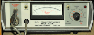
9301A - True RMS Millivoltmeter
10KHz to 1.5GHz
10KHz to 1.5GHz
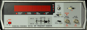
9916 - 520MHz Frequency Counter
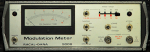
9008 - Modulation Meter
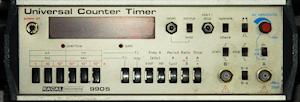
9905 - Universal Timer Counter
Branded as Racal Instruments, so maybe not 'Racal-Dana'. But the model number fits the profile and the case is the same.
Branded as Racal Instruments, so maybe not 'Racal-Dana'. But the model number fits the profile and the case is the same.
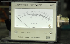
9100 - Absorbtion Wattmeter
1MHz - 1GHz
10mW - 3W in 2 ranges
A surprisingly useful little wattmeter.
1MHz - 1GHz
10mW - 3W in 2 ranges
A surprisingly useful little wattmeter.
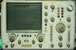
My Tektronix test equipment
This is actually cheating since these aren't actually discrete instruments ...
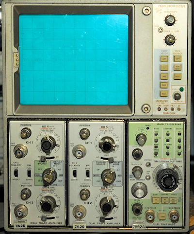
7603 - Oscilloscope Mainframe with
two 7A26 - 200MHz Dual Vertical Amplifiers and
a 7B92A - 500MHz Dual Timebase
two 7A26 - 200MHz Dual Vertical Amplifiers and
a 7B92A - 500MHz Dual Timebase
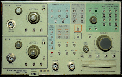
7D20 - Dual Channel 50MHz Programmable Digitizer.
Basically a digital storage oscilloscope in a single module.
Basically a digital storage oscilloscope in a single module.
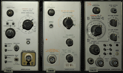
Three more Vertical Amplifiers
7A11 - 250MHz FET-Probe Amplifier
7A19 - 600MHz Amplifier
7A22 - Differential Amplifier
7A11 - 250MHz FET-Probe Amplifier
7A19 - 600MHz Amplifier
7A22 - Differential Amplifier
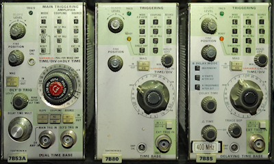
Three more Timebase modules
7B53A - 100MHz Dual Timebase
7B80 - 400MHz Single Timebase without delay
7B85 - 400MHz Delaying Timebase
7B53A - 100MHz Dual Timebase
7B80 - 400MHz Single Timebase without delay
7B85 - 400MHz Delaying Timebase
Left: 7D13 - A 3-and-a-half digit Digital Multimeter with CRT readout for 7000-series mainframes. Can also be used to measure temperature with P6058 probe (which I don't have).
The bandwidth and speed of the various plug-ins is wholly dependent on the particular 7000-series mainframe used. To achieve maximum bandwidth, ideally 7800 or 7900 mainframes should be used.
For full details on vintage Tektronix hardware go to TekWiki
Other miscellaneous, but equally important test equipment
Marconi 893B Audio Power Meter
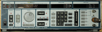
Adret 740A Synthesized RF Signal Generator
100KHz - 1120MHz
This quirky French-made synthesizer was full of faults when I got it. It took me a while to collect the relevent manuals, but not before I had managed to repair it.
100KHz - 1120MHz
This quirky French-made synthesizer was full of faults when I got it. It took me a while to collect the relevent manuals, but not before I had managed to repair it.
Receiver sensitivity is all about signal-to-noise ratio. I have heard some truly weird methods that people have used to try to ascertain the sensitivity of their receivers. Many of these methods actually require your ears to be calibrated ... which they're not!
The simplest way to check a receiver's sensitivity is like this ... Let's check a Racal RA17 at 1.5MHz for 1uV at 3KHz IF B/W ...
Receiver initial settings:
RF/IF Gain to Max
AGC (AVC) OFF.
BFO ON.
RF attenuator to minimum.
IF Bandwidth to 3KHz.
Set the meter to indicate RF level.
Method:
Set the RF signal source to 1.5MHz CW, and set the output level to 1uV emf.
Connect the signal source to the receiver's input and tune the receiver (e.g. RA17) for maximum indication on the meter, adjusting the preselector accordingly.
Connect the external audio output to an audio wattmeter like the Marconi 893B and carefully adjust the BFO for maximum audio level on the wattmeter.
Turn the volume up full. Switch off the receiver's internal loudspeaker if present. It is important that the wattmeter impedance is set to match the expected external speaker impedance.
In the case of the RA17/RA17L, use the external 3-ohm output. This should give over 300mW into the wattmeter. If you can't achieve that, turn the volume down and go for a level that exceeds 100mW. The actual level is not too important.
Now back the RF/IF gain control off until the reading on the wattmeter is 300mW (or 100mW), then make a final adjustment so that the needle on the wattmeter aligns with 0dB. This is your initial reading.
Now switch off the RF output from the signal source, or disconnect the signal source from the receiver and terminate the aerial connector appropriately.
Verify that the reading on the wattmeter drops significantly.
Now measure the receiver audio power into the wattmeter. For a factory-spec RA17 you should expect a level something like 20dB down on your initial measurement.
This is the receiver's sensitivity in terms of signal-to-noise ratio, or more correctly signal plus noise-to-noise.
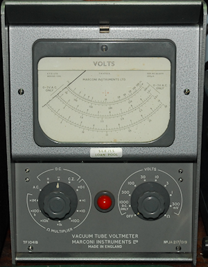
Marconi TF-1041B Valve Voltmeter
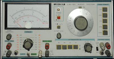
Leader LAV-191 Audio Test Set
Sine/Square-wave Generator 10Hz - 1MHz
2-Channel rms Voltmeter 1.5mV - 500V
Sine/Square-wave Generator 10Hz - 1MHz
2-Channel rms Voltmeter 1.5mV - 500V
Above: Two very versatile instruments. Dating from the early 1960s, the Marconi TF-1041B is actually more than just a voltmeter. It is also an RF rms Voltmeter offering an almost flat response from 1KHz up to 500MHz but is useable up to 1.5GHz. It can also measure resistances from 0.02 Ohms to 500 Megohms. I like how it is described as a Vacuum Tube Voltmeter. I wonder if this was for the North American market?
I picked up the LAV-191 when Mitsubishi closed their VCR manufacturing facility down the road some time ago. Since my Adret 740A won't 'go' below 100KHz, the LAV-191 comes in handy for chasing faults in the 100KHz IF strip in RA17s etc. The rms Voltmeter option is extremely useful since the input impedance is 10 Megohms, whereas the Racal-Dana 9301A is either 100K or 50R.
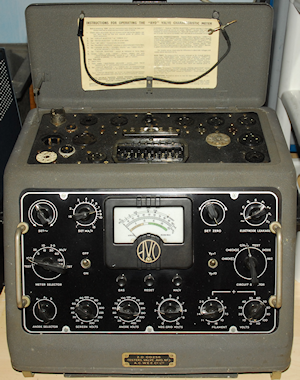
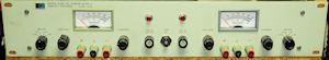
AVO VCM MKII
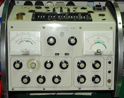
AVO VCM-163
I count myself extremely fortunate in having these two AVO valve testers, or Valve Characteristic Meters. Each caters for several valve bases that the other doesn't, hence the reason for keeping the MKII when I acquired the VCM-163. I have heard of people who have extended the 'repertoir' of one valve tester by simply connecting a multiway cable between it and another tester. I admit that this sounds really innovative and a clever way to include the bases of one tester with another. However after some thought on the matter, I'm not sure that linking two testers in this way is actually a good idea. AVO make it very clear that the wiring layout under the top of their testers is layed out in such a way as to minimise the risk of parasitic oscillation. Thus linking two testers via the test sockets sounds to me like it might actually increase the risk of oscillation. My VCM-163 had previously been linked to a MK4 AVO VCM in this way and when I received it I found it to have several burned out resistors inside. I can't prove it, but I suspect that the resistors were burned out as a result of induced parasitic oscillations.
As a refurbisher of vintage military radios, I have come to see such intruments as an absolute necessity. As well as identifying serious faults, over the years, I have found that replacing valves with the slightest indication of inter-electrode leakage can improve the over-all signal-to-noise figure.
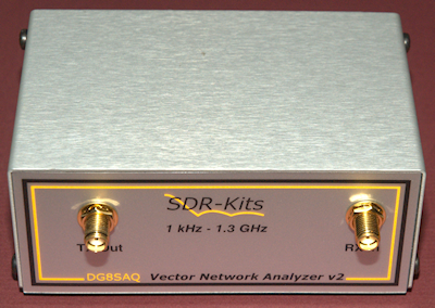
DG8SAQ VNWA v2.6
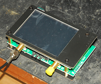
nanoVNA V2
I built my SDR-Kits VNWA V2.6 from a kit way back in 2010! As a 2-port Vector Network Analyzer, it is 'good' up to 1.3GHz. Although I have done a significant amount of microwave home-contruction, right up to 24GHz, I actually invested in the DG8SAQ VNWA primarily to enable me to align the 40MHz Band-Pass filter in the RA17 series of receivers. Although this is a 50-ohm device, and the 40MHz filter is definitely NOT 50-ohm, I have not had any problems and the results that I have achieved speak for themselves.
On the right we have my newly acquired nanoVNA V2 from OwOComm. This is a truly remarkable little instrument. Not only is it smaller than the DG8SAQ VNWA but it incorporates its own colour 'touch-screen', is 'good' up to 3GHz and useable up to 4GHz. Although it can be controlled via the built-in micro-USB port, it is otherwise fully self-contained. How technology has changed in 10 years! Back in the late 80s the 'Holy-Grail' of RF network analysis was the HP8510 which still required an external sweep oscillator ... and before that it was the HP8409 which involved a whole rack of equipment, all controlled by an HP9826A computer. I shall leave the description of both of these setups for another blog entry.
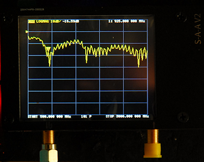
On the right is a plot on the nanoVNA V2 of a GSM/UMTS multiband dipole between 500MHz and 3GHz.
This morning I tested my own microwave yagis using the nanoVNA V2. Examining the frequency response of ANY antenna down a length of coax is always going to be compromised by the VSWR of the transmission-line itself, however it did turn out to be an interesting exercise with enlightening results.
My 23cm 35-ele Tonna appeared to resonate at 1290MHz whilst my 13cm 25-ele Tonna was resonant at 2.3GHz and my home-brew 48-ele Quad-Loop yagi for 9cm was spot-on at 3.4GHz!
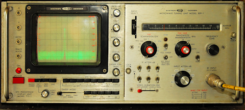
Left: I almost forgot about my trusty Systron-Donner Spectrum Analyser (10MHz to 12.4GHz).
Here it is displaying a 450MHz 1mW signal from the Adret 740A.
Note the re-labelled 'reversed' replacement input attenuator.
Next post in the series: Two Adret Signal Generators