A Home-Made J-Switch for the T.1154
4 minute read
November 2011
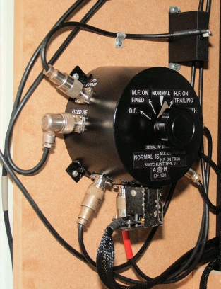
Home-Made J-Switch
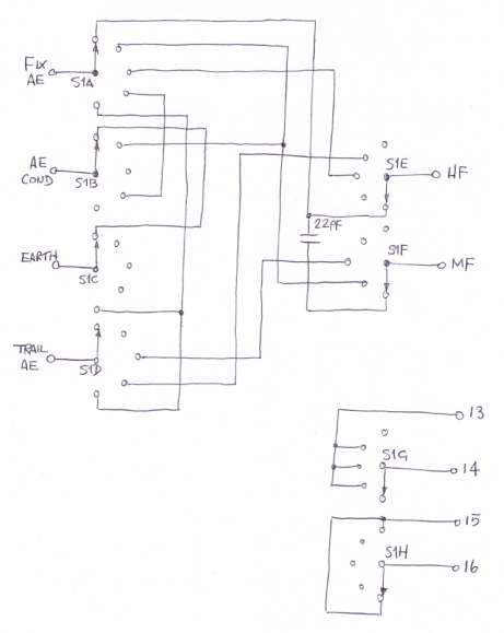
Home-Made J-Switch Schematic
As with most of the rotary switches in the T1154 and R1155, the wafers are not generic, they are ‘custom’. It isn’t difficult to see that this was done in order to simplify the wiring. Obtaining four and eight-pin Jones connectors isn’t easy, but neither is it impossible. The strange round connectors used for the Aerial and Earth connections on the side of the T1154, the J-Switch and the External AE Ammeter in-line with the HF Aerial are a different story. It is possible to obtain replicas from G4CVU, but as with a lot of replica parts, someone had to make to the ‘pattern’ and thus these can be expensive. Similarly, a complete J-Switch will also command a premium price on the second-and market. So I decided to take the less expensive approach and make my own J-Switch. Switch S1 is a high quality 8-pole, 5-way ceramic switch. Pins 13 through 16 are a standard 4 pin Jones connector as per the original. The remaining 4 inputs and 2 outputs are reduced-flange SO239 sockets. The use of reduced-flange connectors makes it easier to mount them around the circumference of the round enclosure which is actually the transformer housing from a failed IKEA light fitting!
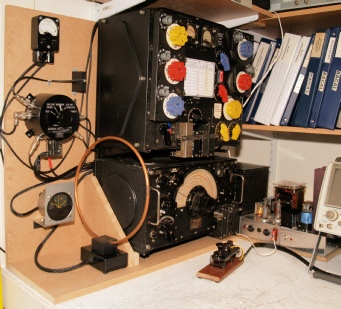
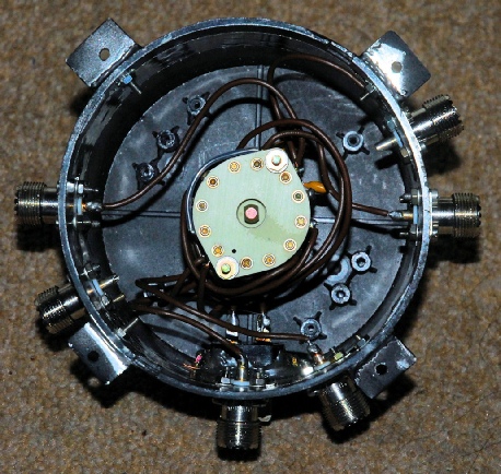
The photograph above left shows the home-made J-Switch and Aerial Condenser installed with the complete TX/RX setup. The photograph on the right shows the inside of the home-made J-Switch. The wires to the Aerial Condenser and Earth sockets were not in place at this time. A conductive strip of tin can just be seen linking all the SO239 connectors together.
... and Home Made Case Screws for the T.1154
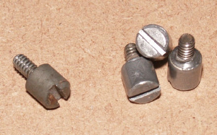
If you can’t get any original T1154 case screws … make your own!
These were easier to make than I envisaged. First of all you will need to find some suitable 3/16 BSW threaded screws. I found some 3/8 inch diameter brass tubing which I bought from a model shop many years ago. This is the exact diameter of the head of the case screw. Using a pipe cutter, I cut three lengths to match the case screw on the left. The 3/16 BSW screws were carefully positioned inside the brass tube which was then carefully filled with epoxy resin. When the resin is cured, bevel the top and file a wide slot using a needle file. I finally sprayed them with what was supposed to be a chrome finish paint. But it turned out more like steel … which suited the job even better. I think they look quite realistic.
These were easier to make than I envisaged. First of all you will need to find some suitable 3/16 BSW threaded screws. I found some 3/8 inch diameter brass tubing which I bought from a model shop many years ago. This is the exact diameter of the head of the case screw. Using a pipe cutter, I cut three lengths to match the case screw on the left. The 3/16 BSW screws were carefully positioned inside the brass tube which was then carefully filled with epoxy resin. When the resin is cured, bevel the top and file a wide slot using a needle file. I finally sprayed them with what was supposed to be a chrome finish paint. But it turned out more like steel … which suited the job even better. I think they look quite realistic.