RA17 MKII Ser. N2751
15 minute read
December 2020
Back in October this year, I took this MKII RA17 as part payment for another job, and I wouldn't have automatically written this report had it not turned out to be so interesting. When it arrived I was immediately struck with the apparently good condition of the front panel. Since the intention was to ultimately perform a full refurb I temporarily removed the top and bottom covers. With the top cover off I was able to quickly verify that the Ernest Turner meter did in fact work ... and a quick peek into the PSU/Audio compartment confirmed that the three wire-wound resistors had already been changed over to metal-clad types as per EMER E727 Mod. Instr. No.19. Basically we were 'good to go' as soon as my current work-load permitted.
It worked ... but sensitivity was definitely 'down' and, Oh boy!, was it noisy?! Looking at the state of the resistors in the 100KHz IF strip, I was not surprised ... but these would have to wait.
Removing the VFOs from the chassis is a major undertaking. First of all, the front panel must first be removed. Then in order to remove the 1st VFO, the 2nd VFO must first be removed. And to achieve this the 2nd VFO top cover must be removed to gain access to one of the 2BA screws.
The 1st VFO module actually incorporates the RF amplifier with pre-selector, the 1st VFO and 1st mixer. Nothing untowards was encountered in this case other than most of the resistors being 30% high in value, which is to be expected in an RA17 from March 1960.
Moving on now to the 2nd VFO module and things are about to get nasty. As can be seen from the photograph on the right, the capacitors on the back of the tag-board have been getting hot as have the components on the front of the board. This level of damage is actually a normal occurrence. It isn't uncommon to find pools of congealed wax on the inside of the bottom cover. This wax having leaked out from the Hunts capacitors once they had morphed into resistors.
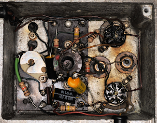
Left: The re-assembled tag-board re-installed in the 2nd VFO. All the carbon resistors and tubular paper capacitors have been replaced. The wire-wound resistor on the tag-board was measured and found to be well within tolerance, so was not replaced. Out of close to 50 RA17s I have only had to replace this resistor on two occasions. The inside of the compartment was obviously cleaned before re-assembly.
The 2nd VFO module was then tested on my 2nd-VFO Test-Set where the frequency linearity between 2.1MHz and 3.1MHz was found to be within 1KHz over the entire range. Both VFOs were set aside whilst I attended to the input attenuator and a couple of assemblies which are literally impossible to access unless the VFOs are off the chassis.
I then re-fitted both VFOs onto the chassis and re-tested the receiver. Although there was a very slight improvement in sensitivity, the noise level was still very high. This was not unexpected as experience has proved again and again that the most likely cause of noise and lack of sensitivity is actually the 100KHz module which also incorporates the AGC circuitry.
As expected, the 3rd IF or 100KHz strip yielded some shockingly bad resistors. The majority were at least 30% high in value. Some were so badly 'cooked' that their colour banding was not readable. In the case of R120 and R121, two 100K 1/2W resistors in parallel ... both were badly cooked, one was open-circuit whilst the other measured a whopping 500K. The BFO which sits on top of this module was found to be inoperative. Curiously the cause turned out to be exactly the same as encountered in a previous receiver. In both cases the DC levels in the BFO were correct but no oscillation. In both cases the fault was traced to a build up of grime between the vanes of the enclosed trimmer capacitor C201, increasing its value from nominally 35pF (50% meshed) to several hundred nanofarads!
And so we come to another potentially dangerous wiring error. As long ago as 1976, this receiver was partially refurbished. The red 'R' on the rear panel would indicate this. It was at this time that I believe most of the notorious Hunts capacitors were replaced with the yellow polyester capacitors as in the above photograph. However, whoever did this, did it without removing the IF-bandwidth selector control shaft ... thus severely limiting access to the four tag-boards. Wherever a Hunts capacitor was replaced, the original was simply cut out and the replacement clumsily soldered onto the original joints, BADLY. I have therefore systematically de-soldered every single joint and removed all the abandoned wires before carefully re-fitting all the yellow polyester capacitors. It was whilst doing this that I found this accident waiting to happen. In the photograph on the left, see the vertical wire. This is the 'un-clipped' end of a replacement 47nF capacitor (C187). This wire was at approximately 100V and a hair's breadth away from a wire at 0V potential!
All the carbon resistors and original tubular paper capacitors in the 100KHz IF strip and BFO have now been replaced. The module was refitted to the main chassis, and on re-testing the receiver, the improvement was staggering. Not a very technical term, I know, but in the absence of an aerial, I had to turn the volume up full in order to hear the background noise.
The Harmonic Mixer compartment can be a tricky area to change components in since many share the same earthy tie-points. The order in which they are changed is therefore largely dictated by the order in which they were connected to the shared 'ground'. No serious issues encountered here and in the adjacent Oscillator compartment ... although I did notice that someone had been filling the ends of the tuneable inductors with candle-wax!
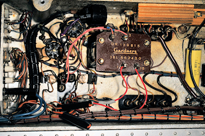
Gardners Audio Transformer
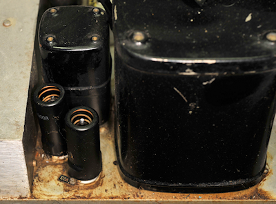
Then at the end of November, I heaved the RA17 onto the bench, tipped it onto its side (with the top and bottom covers removed) intending to power it up via a variac ... always a good idea, just in case! It was only then that I noticed the 'rogue' transformer hiding in the PSU/Audio compartment. How on earth had I missed this?! Looking around in the immediate area I noticed that the wiring to the larger of the two audio transformers (T2) had been modified. The wires to the external-speaker connections had been neatly isolated and replaced with two blue wires, expertly integrated into the loom and connecting to a modern(ish) 1/4-inch jack-socket, replacing the LH E.S.F socket. The Gardners transformer turned out not to be a modification but a repair. The original transformer (still on the chassis) showing as having an open-circuit primary winding ... hmmm?
Powering up this receiver was no longer my first priority. Removing the side-panel adjacent to the mains transformer revealed an unpleasant surprise. Something had leaked oil in the vicinity of V22 and V23. Was it the mains transformer (T1) or T3, the smaller audio transformer? This was indeed worrying; although someone had clearly mopped up the mess, albeit a tad short of complete. Had the leak occurred before or after the under-chassis modification/repair work was implemented? More questions to be addressed.
I surmised that perhaps V23 had failed catastrophically, resulting in excessive anode-current in the primary winding of T3, resulting in a build-up of pressure from the subsequent heat produced. The consequence of which being the outflow of oil. I really hoped it was not from the mains transformer!
An expedition into the loft yielded a scrap RA218 with a couple of good but grubby audio transformers which I knew were identical to T3 in the RA17. I cleaned one up and set it aside whilst I checked all the valves in the RA17 on my VCM-163. This exercise yielded a total of four duff valves; two of which exhibited internal open-circuits (no anode current). Interestingly, V22 and V23 both tested good.
With all the valves now tested and the four duff ones replaced, I set about undoing the mods that I had previously identified. The non-original 1/4-inch audio jack-socket on the front panel was replaced with an original E.S.F. socket. Since the original wiring had been left in place and neatly isolated, it was simply a case of removing the two blue wires (in the photograph above) and re-attaching the original wires. In the same way, the rear-panel external speaker wiring was re-attached to T2. The Gardners transformer was extracated as was the faulty T3 and its replacement fitted. I was now in a position where I now felt it was safe to tentatively power up the RA17 via the variac ... but not before I re-stuffed the smoothing pack in the PSU and replaced the usual Rs and Cs in the audio stages.
Evidence of oil leakage
Powering up this receiver was no longer my first priority. Removing the side-panel adjacent to the mains transformer revealed an unpleasant surprise. Something had leaked oil in the vicinity of V22 and V23. Was it the mains transformer (T1) or T3, the smaller audio transformer? This was indeed worrying; although someone had clearly mopped up the mess, albeit a tad short of complete. Had the leak occurred before or after the under-chassis modification/repair work was implemented? More questions to be addressed.
I surmised that perhaps V23 had failed catastrophically, resulting in excessive anode-current in the primary winding of T3, resulting in a build-up of pressure from the subsequent heat produced. The consequence of which being the outflow of oil. I really hoped it was not from the mains transformer!
An expedition into the loft yielded a scrap RA218 with a couple of good but grubby audio transformers which I knew were identical to T3 in the RA17. I cleaned one up and set it aside whilst I checked all the valves in the RA17 on my VCM-163. This exercise yielded a total of four duff valves; two of which exhibited internal open-circuits (no anode current). Interestingly, V22 and V23 both tested good.
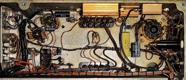
With all the valves now tested and the four duff ones replaced, I set about undoing the mods that I had previously identified. The non-original 1/4-inch audio jack-socket on the front panel was replaced with an original E.S.F. socket. Since the original wiring had been left in place and neatly isolated, it was simply a case of removing the two blue wires (in the photograph above) and re-attaching the original wires. In the same way, the rear-panel external speaker wiring was re-attached to T2. The Gardners transformer was extracated as was the faulty T3 and its replacement fitted. I was now in a position where I now felt it was safe to tentatively power up the RA17 via the variac ... but not before I re-stuffed the smoothing pack in the PSU and replaced the usual Rs and Cs in the audio stages.
Replacement audio transformer fitted ... compartment refurbished.
It worked ... but sensitivity was definitely 'down' and, Oh boy!, was it noisy?! Looking at the state of the resistors in the 100KHz IF strip, I was not surprised ... but these would have to wait.
1st VFO module, refurbished
Removing the VFOs from the chassis is a major undertaking. First of all, the front panel must first be removed. Then in order to remove the 1st VFO, the 2nd VFO must first be removed. And to achieve this the 2nd VFO top cover must be removed to gain access to one of the 2BA screws.
The 1st VFO module actually incorporates the RF amplifier with pre-selector, the 1st VFO and 1st mixer. Nothing untowards was encountered in this case other than most of the resistors being 30% high in value, which is to be expected in an RA17 from March 1960.
Once refurbished and the metalwork cleaned, the VFO was placed on my 1st-VFO Test-Set and re-aligned. i.e. the pre-selector was re-tuned as per the manual (it was badly out of alignment) and the VFO upper and lower limits reset. Finally the mixer stage was verified as working using my spectrum analyser.
1st VFO inside, before refurbishment
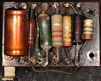
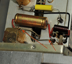
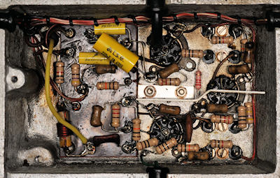
Moving on now to the 2nd VFO module and things are about to get nasty. As can be seen from the photograph on the right, the capacitors on the back of the tag-board have been getting hot as have the components on the front of the board. This level of damage is actually a normal occurrence. It isn't uncommon to find pools of congealed wax on the inside of the bottom cover. This wax having leaked out from the Hunts capacitors once they had morphed into resistors.
Tag-Board front, before
Tag-Board front, after
Tag-Board rear, after
1st VFO inside after refurbishment
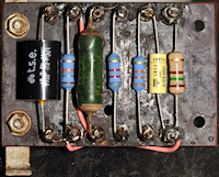
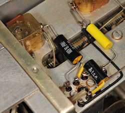
Left: The re-assembled tag-board re-installed in the 2nd VFO. All the carbon resistors and tubular paper capacitors have been replaced. The wire-wound resistor on the tag-board was measured and found to be well within tolerance, so was not replaced. Out of close to 50 RA17s I have only had to replace this resistor on two occasions. The inside of the compartment was obviously cleaned before re-assembly.
Wiring error
Here's evidence of a failure in quality control. In the photograph on the left, the two older tubular capacitors are actually there as safety mods, isolating parts of the receiver from HT+ potential. A serious error has been made when fitting the larger of the two. The wire that the capacitor is intended to replace has been left in place. The photograph on the right shows the correct wiring.
Correct wiring
The 2nd VFO module was then tested on my 2nd-VFO Test-Set where the frequency linearity between 2.1MHz and 3.1MHz was found to be within 1KHz over the entire range. Both VFOs were set aside whilst I attended to the input attenuator and a couple of assemblies which are literally impossible to access unless the VFOs are off the chassis.
I then re-fitted both VFOs onto the chassis and re-tested the receiver. Although there was a very slight improvement in sensitivity, the noise level was still very high. This was not unexpected as experience has proved again and again that the most likely cause of noise and lack of sensitivity is actually the 100KHz module which also incorporates the AGC circuitry.
3rd IF, 100KHz strip after refurbishment
As expected, the 3rd IF or 100KHz strip yielded some shockingly bad resistors. The majority were at least 30% high in value. Some were so badly 'cooked' that their colour banding was not readable. In the case of R120 and R121, two 100K 1/2W resistors in parallel ... both were badly cooked, one was open-circuit whilst the other measured a whopping 500K. The BFO which sits on top of this module was found to be inoperative. Curiously the cause turned out to be exactly the same as encountered in a previous receiver. In both cases the DC levels in the BFO were correct but no oscillation. In both cases the fault was traced to a build up of grime between the vanes of the enclosed trimmer capacitor C201, increasing its value from nominally 35pF (50% meshed) to several hundred nanofarads!
Dangerous un-cut wire!
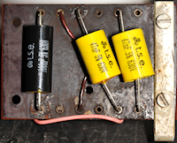
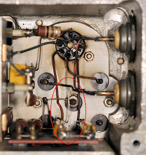
And so we come to another potentially dangerous wiring error. As long ago as 1976, this receiver was partially refurbished. The red 'R' on the rear panel would indicate this. It was at this time that I believe most of the notorious Hunts capacitors were replaced with the yellow polyester capacitors as in the above photograph. However, whoever did this, did it without removing the IF-bandwidth selector control shaft ... thus severely limiting access to the four tag-boards. Wherever a Hunts capacitor was replaced, the original was simply cut out and the replacement clumsily soldered onto the original joints, BADLY. I have therefore systematically de-soldered every single joint and removed all the abandoned wires before carefully re-fitting all the yellow polyester capacitors. It was whilst doing this that I found this accident waiting to happen. In the photograph on the left, see the vertical wire. This is the 'un-clipped' end of a replacement 47nF capacitor (C187). This wire was at approximately 100V and a hair's breadth away from a wire at 0V potential!
All the carbon resistors and original tubular paper capacitors in the 100KHz IF strip and BFO have now been replaced. The module was refitted to the main chassis, and on re-testing the receiver, the improvement was staggering. Not a very technical term, I know, but in the absence of an aerial, I had to turn the volume up full in order to hear the background noise.
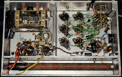
Harmonic Mixer and 37.5MHz Amplifiers
1MHz Osc. and Harmonic Generator
The Harmonic Mixer compartment can be a tricky area to change components in since many share the same earthy tie-points. The order in which they are changed is therefore largely dictated by the order in which they were connected to the shared 'ground'. No serious issues encountered here and in the adjacent Oscillator compartment ... although I did notice that someone had been filling the ends of the tuneable inductors with candle-wax!
The singularly awkward 2nd Mixer
I won't pretend that the RA17 is easy to work on ... and I will confess that after refurbishing 48 of them, I have had the time to experiment with and develop techniques for either removing or accessing various parts in a way that is least invasive (or destructive, even). Due to its shape, the 2nd Mixer compartment is particularly awkward for several reasons. R66 (1K) and R62 (10K) share the same bottom terminal on the HT choke. Access is very tight due to the proximity of the choke to the compartment wall. There is just enough space to squeeze a Weller soldering iron in there once C131 (1nF) is temporarily removed. C117 (10nF), top left in the compartment is connected to the ground tag of trimmer capacitor C108. This may not immediately appear to be tricky until you realise that the other side of C108 is at 220V! If for any reason the vanes of C108 are shorted and HT applied, R66 goes up in smoke! Trust me, I've seen it happen. All you need is a tiny fleck of solder to get in there and the result is smoke. So here's a valuable tip ... When working in this area, set the vanes of C108 fully meshed first!!
I forgot to take photographs of the Calibrator module. As with the 1MHz Oscillator, someone had filled the tops of the two tuneable inductors with candle-wax ... which fortunately, was easy to remove. I also noticed that this was NOT the original calibrator for this receiver. As with later models, the individual valve sockets throughout the receiver all have little anodised tags with the individual valve number on them. In this case there are no such tags for the valves in the calibrator. Also, whilst the 1st VFO sports the Tufnol block for screwing down one end of the calibrator, the calibrator was missing the L-bracket for this purpose and instead sported the Tufnol leg found on early calibrators. I simply unscrewed the leg from the removable cover and after drilling a couple of holes in the end of the calibrator, I fitted an L-bracket salvaged from a scrap unit.
Nothing untoward found in the calibrator other than finding that R84, normally 1M had been changed to 22K, suggesting that this receiver, or the one that the calibrator had been removed from, had been connected to an MA1350A Decade Frequency Oscillator at some time. GCHQ are known to have used this configuration.
That concluded the electrical refurbishment ... now for the realignment. Theoretically the RA17 can be realigned with just a calibrated signal source and an rms voltmeter, or an oscilloscope. But to align the IF filters would be labouriously tedious. Which is why the Wobbulator was invented. I've got several rms voltmeters and I even have a Racal Wobbulator ... the SA97, which I may add whilst being completely un-calibratable, it is a wonderful talking-point.
The RA17 series relies on the Wadley drift-cancelling configuration which is widely, but incorrectly referred to as the Wadley Loop. Basically it isn't a loop ... but we won't go down that hole! Crucial to the operation of the drift cancelling system are two highly critical Band-Pass filters. One of these is loose-coupled and tuned to 37.5MHz. The other is over-coupled and centred on 40.5MHz. Where-as the former can theoretically be peaked by observing the needle on the front-panel meter, the latter requires the use of a wobbulator with a means of displaying the shape of the filter in real-time. This was my reason for investing in the DG8SAQ Vector Network Analyser.
Thus the first point of re-alignment is always the 40MHz filter. Sometimes it is evident that someone has been 'twiddling' and I have to spend a while re-shaping the filter. More often than not some re-shaping is required. There is no rule as to which trimmer controls which part of the curve. ALL the 'elements' are co-dependent and interactive, so it is largely an intuitive iterative process. I use the DG8SAQ VNWA for shaping the filters in the 100KHz module too with great success. Recently I have also been using the VNWA to adjust the 37.5MHz filter and the associated tuned amplifier stages ... essentially everything between TP1 and TP3.
Racal's original specification was for a 20dB signal-to-noise ratio for 1uV CW or 3.5uV AM with an IF Bandwidth of 3KHz.
RA17 N2751 exceeds these figures thus ...
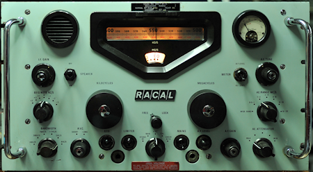
 Above: Two photographs of the finished receiver. As you can see it sports an unusual yet pleasing large Racal badge. Ideally I would have like to have replaced it with an original red and gold enamel badge, however it looks like this one has been glued on and I am unwilling to risk damaging a large area of paintwork in the process. There are two very small scratches on the front panel just below the Bandwidth knob, and the front panel is very slightly bent at the extreme right. This is not uncommon and is probably due to 'heavy handling' when it was literally wrenched out of a cabinet at the end of its service life. In this case the bend is very slight an totally unnoticeable from the front. The aerial connector has been replaced with an SO-239 connector. The mains connector is the 'standard' Plessey type but possibly not the original MK4 connector and looks to be a MK7 ... similar, but different thread.
I forgot to take photographs of the Calibrator module. As with the 1MHz Oscillator, someone had filled the tops of the two tuneable inductors with candle-wax ... which fortunately, was easy to remove. I also noticed that this was NOT the original calibrator for this receiver. As with later models, the individual valve sockets throughout the receiver all have little anodised tags with the individual valve number on them. In this case there are no such tags for the valves in the calibrator. Also, whilst the 1st VFO sports the Tufnol block for screwing down one end of the calibrator, the calibrator was missing the L-bracket for this purpose and instead sported the Tufnol leg found on early calibrators. I simply unscrewed the leg from the removable cover and after drilling a couple of holes in the end of the calibrator, I fitted an L-bracket salvaged from a scrap unit.
Nothing untoward found in the calibrator other than finding that R84, normally 1M had been changed to 22K, suggesting that this receiver, or the one that the calibrator had been removed from, had been connected to an MA1350A Decade Frequency Oscillator at some time. GCHQ are known to have used this configuration.
That concluded the electrical refurbishment ... now for the realignment. Theoretically the RA17 can be realigned with just a calibrated signal source and an rms voltmeter, or an oscilloscope. But to align the IF filters would be labouriously tedious. Which is why the Wobbulator was invented. I've got several rms voltmeters and I even have a Racal Wobbulator ... the SA97, which I may add whilst being completely un-calibratable, it is a wonderful talking-point.
The RA17 series relies on the Wadley drift-cancelling configuration which is widely, but incorrectly referred to as the Wadley Loop. Basically it isn't a loop ... but we won't go down that hole! Crucial to the operation of the drift cancelling system are two highly critical Band-Pass filters. One of these is loose-coupled and tuned to 37.5MHz. The other is over-coupled and centred on 40.5MHz. Where-as the former can theoretically be peaked by observing the needle on the front-panel meter, the latter requires the use of a wobbulator with a means of displaying the shape of the filter in real-time. This was my reason for investing in the DG8SAQ Vector Network Analyser.
Thus the first point of re-alignment is always the 40MHz filter. Sometimes it is evident that someone has been 'twiddling' and I have to spend a while re-shaping the filter. More often than not some re-shaping is required. There is no rule as to which trimmer controls which part of the curve. ALL the 'elements' are co-dependent and interactive, so it is largely an intuitive iterative process. I use the DG8SAQ VNWA for shaping the filters in the 100KHz module too with great success. Recently I have also been using the VNWA to adjust the 37.5MHz filter and the associated tuned amplifier stages ... essentially everything between TP1 and TP3.
Racal's original specification was for a 20dB signal-to-noise ratio for 1uV CW or 3.5uV AM with an IF Bandwidth of 3KHz.
RA17 N2751 exceeds these figures thus ...
Freq:
1.6MHz
14.5MHz
28.5MHz
1.6MHz
14.5MHz
28.5MHz
CW
30dB
31dB
30dB
30dB
31dB
30dB
AM
26dB
27dB
26dB
26dB
27dB
26dB