Systron Donner Spectrum Analyzer Type 809-1 re-fit
4 minute read
This post is part of the series 'Systron-Donner Type 809-1':
The length of 15mm pipe fits neatly over the attenuator shaft which now extends into the hole in the front panel. The pipe section effectively takes the place of the original 12.6mm shaft giving the nut something to tighten against. It works really well and the right-angled SMA adapter on the attenuator output now only 'kisses' the IDC connector on the A206 board. The original attenuator looks like a 'custom job' with the offset N-connector integrated into the body. Fortunately I had a bulkhead mounting N-to-SMA adapter at hand. A thin semi-flexi cable provides the link between the analyzer input and the attenuator. The attenuator output is an SMA-Male which needs to connect to a port on a power-combiner. This is achieved by way of a length of semi-rigid coax and a right-angled SMA-adapter. The power combiner would normally be screwed onto a bracket on the original attenuator but is now only supported by two semi-rigid cables. Although the attenuator worked perfectly, the anyalyzer was still a bit deaf. So I swapped the 'new' detector for the original and 'BINGO!' the analyzer is once again sensitive. I can actually see Medium Wave signals when I connect my Inverted-V aerial to the input ... despite the 809-1 only being spec'd down to 10MHz. Apologies for the fluff on the video switch.
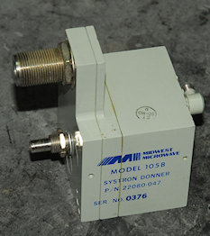
The original Mid-West Microwave attenuator is relatively easy to split. The elements are mounted like cartidges in a revolver. The 10dB element measured 60-ohms, the 20dB element measured a whopping 185-ohms and showed evidence of burning. The remaining elements all measured around 48-ohms, which sounds about right, although two of them were badly tarnished. Also, I found serious burn damage on the spring-loaded tip which the revolving elements come in contact with.
The Weinschel attenuator works well albeit in reverse ... 60dB on the front panel is 0dB, but I can easily fit little stick-on labels to reflect the change.
I have to conclude that it was the attenuator (intermittent?) all along which had made me think the detector was faulty. With the new Weinschel unit fitted, the analyzer is more sensitive than ever but I am definitely NOT happy with the frequency calibration, which varies dramatically with the scan-width. Unfortunately without the appropriate extender-cable there is no way of performing the recalibration since the Tuning/Microwave unit needs to be out of the main unit and 'split'. Having identified the required connectors as a 24-way type by Cinch with the respective part numbers 26-159-24 and 26-190-24, I discovered that they appear to be obsolete now. A couple of UK suppliers did stock them (or equivalents) a few years ago, but they are missing from current catalogues. HOWEVER, I am most grateful to Allen Wallace, N7CGH, who very generously sent me a pair of connectors, enabling me to make up the extender cable. There isn't a definitive wiring schedule for the cable and I had to refer to two different schematics in the service manual to ascertain the actual 'pin-out' and wiring types. I will post a progress report giving details of the cable once I have completed the calibration.
Next post in the series: Systron Donner Spectrum Analyzer Type 809-1 - Solving the Frequency Calibration Issue
- Systron Donner Spectrum Analyzer Type 809-1
- Systron Donner Spectrum Analyzer Type 809-1 re-fit
- Systron Donner Spectrum Analyzer Type 809-1 - Solving the Frequency Calibration Issue
May 2020
It is now five years since I repaired my Systron-Donner Spectrum Analyzer. It doesn't get a lot of use these days other than verifying that the 1st Mixer is working on RA17s that I have been refurbishing. Then about 18 months ago (I think), I was conscious of the fact that it had gone a bit deaf again. This time I figured it was the 1st mixer that was faulty. I swapped it for a spare and everythng appeared OK again. But I kept the original diode ... for some reason.
However it went deaf again! And flicking through the input attenuator positions revealed that no less than three of the elements were not working. I had known for some time that one of the elements was faulty, but this time the 'rot' appeared to have spread. Five years ago when I attempted to replace this attenuator I ended up abandoning the idea since my replacment, a Weinschel type 9029 was about 1mm too long and fouled on the IDC connecor on the A206 board. Then a few days ago I had a 'light-bulb' moment. I had an idea for making the attenuator appear shorter.
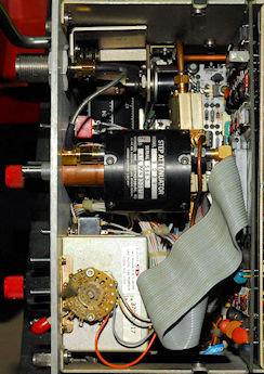
This involved drilling out the hole for the selector shaft to 12.6mm (the diameter of the shaft between the attenuator body and the threaded bush). I then took a length of 15mm copper pipe and carefully cut it such that its length matched the distance between the attenuator body and the right-angled SMA connector screwed into the input connector. See the photograph below.
However it went deaf again! And flicking through the input attenuator positions revealed that no less than three of the elements were not working. I had known for some time that one of the elements was faulty, but this time the 'rot' appeared to have spread. Five years ago when I attempted to replace this attenuator I ended up abandoning the idea since my replacment, a Weinschel type 9029 was about 1mm too long and fouled on the IDC connecor on the A206 board. Then a few days ago I had a 'light-bulb' moment. I had an idea for making the attenuator appear shorter.
This involved drilling out the hole for the selector shaft to 12.6mm (the diameter of the shaft between the attenuator body and the threaded bush). I then took a length of 15mm copper pipe and carefully cut it such that its length matched the distance between the attenuator body and the right-angled SMA connector screwed into the input connector. See the photograph below.
The length of 15mm pipe fits neatly over the attenuator shaft which now extends into the hole in the front panel. The pipe section effectively takes the place of the original 12.6mm shaft giving the nut something to tighten against. It works really well and the right-angled SMA adapter on the attenuator output now only 'kisses' the IDC connector on the A206 board. The original attenuator looks like a 'custom job' with the offset N-connector integrated into the body. Fortunately I had a bulkhead mounting N-to-SMA adapter at hand. A thin semi-flexi cable provides the link between the analyzer input and the attenuator. The attenuator output is an SMA-Male which needs to connect to a port on a power-combiner. This is achieved by way of a length of semi-rigid coax and a right-angled SMA-adapter. The power combiner would normally be screwed onto a bracket on the original attenuator but is now only supported by two semi-rigid cables. Although the attenuator worked perfectly, the anyalyzer was still a bit deaf. So I swapped the 'new' detector for the original and 'BINGO!' the analyzer is once again sensitive. I can actually see Medium Wave signals when I connect my Inverted-V aerial to the input ... despite the 809-1 only being spec'd down to 10MHz. Apologies for the fluff on the video switch.
The original Mid-West Microwave attenuator is relatively easy to split. The elements are mounted like cartidges in a revolver. The 10dB element measured 60-ohms, the 20dB element measured a whopping 185-ohms and showed evidence of burning. The remaining elements all measured around 48-ohms, which sounds about right, although two of them were badly tarnished. Also, I found serious burn damage on the spring-loaded tip which the revolving elements come in contact with.
The Weinschel attenuator works well albeit in reverse ... 60dB on the front panel is 0dB, but I can easily fit little stick-on labels to reflect the change.
I have to conclude that it was the attenuator (intermittent?) all along which had made me think the detector was faulty. With the new Weinschel unit fitted, the analyzer is more sensitive than ever but I am definitely NOT happy with the frequency calibration, which varies dramatically with the scan-width. Unfortunately without the appropriate extender-cable there is no way of performing the recalibration since the Tuning/Microwave unit needs to be out of the main unit and 'split'. Having identified the required connectors as a 24-way type by Cinch with the respective part numbers 26-159-24 and 26-190-24, I discovered that they appear to be obsolete now. A couple of UK suppliers did stock them (or equivalents) a few years ago, but they are missing from current catalogues. HOWEVER, I am most grateful to Allen Wallace, N7CGH, who very generously sent me a pair of connectors, enabling me to make up the extender cable. There isn't a definitive wiring schedule for the cable and I had to refer to two different schematics in the service manual to ascertain the actual 'pin-out' and wiring types. I will post a progress report giving details of the cable once I have completed the calibration.
Next post in the series: Systron Donner Spectrum Analyzer Type 809-1 - Solving the Frequency Calibration Issue