Hallicrafters SX-28
27 minute read
March 2023
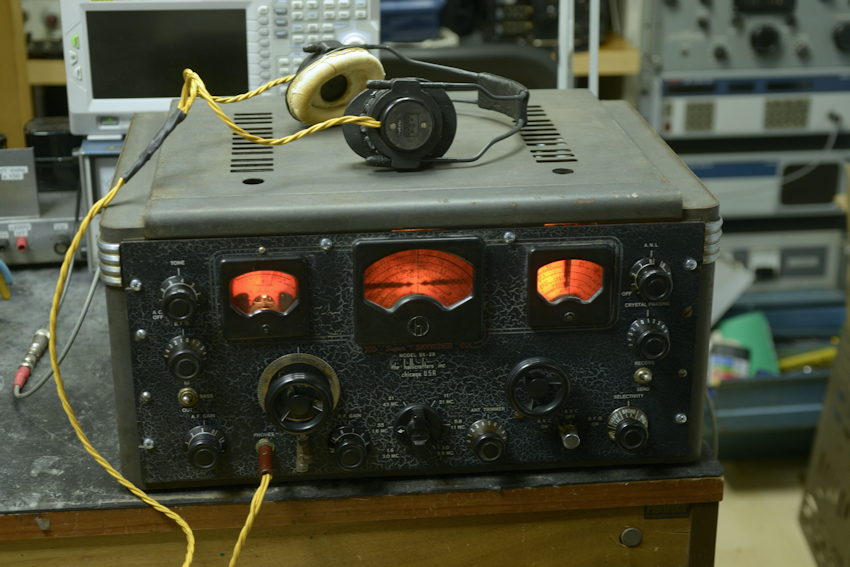
There is no escaping the fact: The Hallicrafters SX-28 is a beast. At 53cm wide by 38cm deep by 27cm high, it weighs in at close to 75 pounds (or 34Kg). Designed in response to over 600 requested reports, the SX-28 was announced in mid 1940. Although primarily aimed at the fast emerging amateur market, it was adopted by various government and military users on both sides of the Atlantic during WW2. It quickly gained legendary performance and reputation, becoming Hallicrafters' flagship. Despite this, production ceased in 1947.
Back in the mid 1970s I came across a Hallicrafters SX-24 in a radio repair shop in Leith. I can't remember how much I paid for it, but it couldn't have been a lot. It didn't have a cabinet and it had been re-painted a horrible magnolia off-white. If I remember correctly, all the panel annotations were on Dymo tape. Not only that, it had been re-valved, with all the Octal valves being replaced with B7G valves. I also believe that a multi-element crystal filter had been added. It worked up to a point, although I don't think it worked on the highest band range. I used it for a while with a 2m converter in conjunction with a DJ9ZR 2m transmitter. It was quite an impressive lash-up. Eventually my SX-24 developed a fault where the audio output would fade away to nothing. If I knew then what I know today about old valve-based receivers, I probably could have repaired it very quickly. But back in 1978, I binned it!
Since then, my only experience with Hallicrafters has been a little S-38. Then last August (2022), a good friend showed me an SX-28 that he had just bought. My first impression was "Its brown!". Not paint though ... rust! Being of steel construction, much of the upper chassis was covered in rust. The top of the tuning-capacitor enclosure was the worst affected. The front panel looked not too bad though, until it became clear that the crackle-finish was severely compromised with rust filling all the 'cracks'.
It was very clear that it was going to be a while before the 'beast' was switched on. Before tackling such a job, it is vital to look for obvious deviations from the original ... what's missing?, or what's been added? Once satisfied that everything was 'there', I set about checking all the valves. The SX-28 has 15 of them, although this one had 16 ... A VR150 stabiliser has been added to provide a more stable Anode voltage for the HF Oscillator. Six of the valves turned out to be faulty ... mostly poor heater-cathode insulation, but one of the 6V6GTs had an internal short. The big 5Z3 directly-heated rectifier behaved very oddly with a distinct purple glow around the twin filaments, indicating the presence of air in the envelope. All the valves for the SX-28 are relatively easy to procure, although 6V6s can command premium prices on some websites due to audiophile demand. Fortunately I had a few new 6V6GTs in my valve cabinet.
With the side plates and front panel removed, I began treating the metal-work with a proprietary rust remover. This entailed wire-brushing or sanding off, where appropriate, the dreaded ferrous oxide before brushing on a rather medicinal-smelling brew which actually fizzed as it dissolved the rust. This process had to be repeated more than a few times in some places until all the rust was gone. According to the bottle, the treated metal-work should then be wiped clean with methylated spirits. I remember from my high-school days that mixing an acid and an alcohol produces an ester, which often has a distinct smell, but I suspect the typical whiff of the meths was a tad overpowering. Exactly what was in the rust eating brew is unclear ... nothing on the bottle, other than a stern warning not to get it on your skin as it could cause burns etc. Whatever it is, it definitely worked, although it had little effect on my skin ... but then again, my hands are like leather!
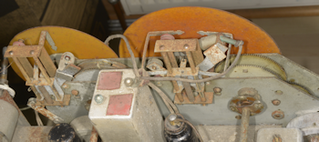
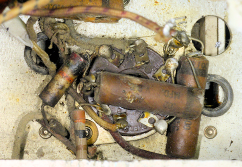
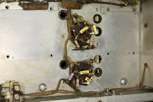
Pointer mechanisms before rust removal.
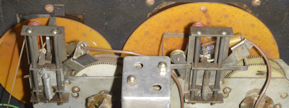
Pointer mechanisms after rust removal.
With the chassis now looking quite presentable, I started trawling the internet for hi-res photographs of the inside of the SX-28. It isn't difficult to find websites devoted to the type, with more than a few showing a restoration project. Yet, its actually quite difficult to find good hi-res photographs that can be enlarged to help identify wiring and component placement. Also, every one of these websites show an SX-28 with shiny spotless metal-work. There is probably a very good reason why this is the case ...
I have a theory ...
When the SX-28 was launched (late 1940), Europe was already in the grips of WW2, ... a little over a year before Pearl Harbour. So until 1945, it was likely that the bulk of SX-28 production went to government and or military users. In the UK, the AR88, HRO and SX-28 were favoured by the Y-Service (Wireless-Intercept Service) which comprised predominantly civilian operators (although a large number of 'Wrens' were enlisted too) who listened in to Axis communications. The SX-28 that arrived on my bench bore the serial number H-142302, which tells us that it was manufactured in December 1941, so unless it found its way to the UK post-WW2, it is very likely that it was 'imported' for the Y-Service. Here in the UK, you are never too far from the sea and a corrosive salty atmosphere. Us brits also have an annoying propensity for storing stuff in sheds, and post-WW2 there was little love for things associated with 6 years of war, so it is likely that a lot of Y-Service equipment ended up languishing in damp sheds ... hence the rust! Like I said, its a theory.
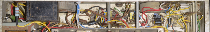
The power supply is always a good place to start. And like the Racal RA17, in the SX-28, the PSU and Audio circuits share the same space. Although in the case of the SX-28, the space is somewhat cramped.
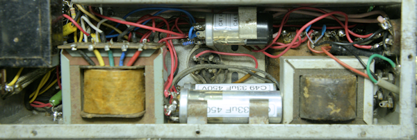
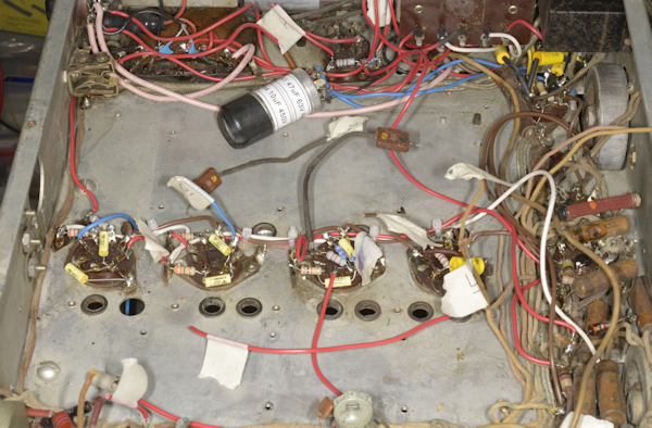
PSU and Audio compartment during refurb.
As this is a relatively early SX-28, it didn't have a chassis mounted Mains fuse, so the first thing I did was to fit one at the rear, to the left of the speaker terminals, as in later models. I also replaced the bulky mains filter capacitors, C51 and C52, with modern ceramic types. Someone had recently stuck a large modern yellow label marked 250V AC on the rear of the tuning capacitor cover. There is a rather small and innocuous slide switch on top of mains transformer for selecting 115V or 230V which appeared to be jammed in the 230V position. I gave it a squirt with DeOxit, and Hey-Presto! it moved! Although I have to admit that it is a little bit worrying that this little switch is very easy to move ... with obvious disastrous results if not careful.
With reference to the photograph above, note the identifying labels on the chassis-mounted capacitors. As is my custom, I re-stuffed the following capacitors ...
C41 (47uF) and C44 (10uF) ... This is the smaller of the three metal-can multi-capacitors, and is associated with V12 (6SC7).
C47 (47uF), C48 (33uF) and C49 (33uF). C48 and C49 form the smoothing pack along with Choke CH1. C47 decouples the cathodes of the two 6V6GTs. Curiously, C48 and C49 are not in the same can, with C48 sharing a can with C47.
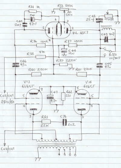
Re-designed audio stage.
The original audio-output transformer had been replaced with one offering speaker taps for 2, 4, 8 and 16-ohms outputs. This could have been out of necessity due to a damaged transformer primary. For example, if either C45 or C46 were to go short-circuit, The anode supply (potentially 280V) for V12 would be applied to the grid of one or other of the 6V6s, causing them to turn on hard, drawing excessive current through the primary winding of the audio output transformer and inevitably burning it out. Or it may have been done to facilitate more common loudspeaker impedances ... the original transformer was wound for 500-ohm and 5000-ohm impedances. This 'new' transformer turned out to be of the 'Super Linear' type with the additional screen-grid taps on the primary winding. I re-designed the output stage to make use of the screen taps ... with excellent results.
The SX-28 is well known as a rather difficult radio to work on, in part due to the unusually deep chassis which makes soldering iron access somewhat difficult. But, not only that, the 'coil-box' on the underside of the chassis is a hideous mechanical contrivance, no doubt designed without future maintenance in mind. The undersides of the V1, V2 and V3 are totally inaccessible. Removing the 'coil-box' is definitely something that you never want to do more than once! Removing the Band Switch and Aerial Trimmer shafts is simple in contrast to actually removing the box itself. Unlike Marconi's gloriously ugly CR100, where the individual compartments can be easily removed, independent of each other ... the SX-28 'coil-box' MUST be dismantled in a particular order, starting at the back. This is necessary because of the interleaved design where the back edge of each mounting plate sits under the mounting plate of the next one (going from front to back), whilst supported by two steel side plates ... see the photographs below..
SX-28 'Coil-Box' underside.
CR100 'Coil-Box' underside.
Removing the divider walls revealed a multitude of 'horrors'. Paper capacitors in urgent need of replacing; various resistors of different types; some looking like they were coated in engine-oil, and cloth-covered wiring that at one time had probably been brightly coloured. Now the spectrum of colours had shifted to mainly beige. This wiring had also been neatly laced up, but not with the expected wax-impregnated lacing cord. Instead, the cord used resembled garden twine, or parcel-string.
At this point, it is probably worth noting that when working on electronic equipment of this era (early 1940s or pre 1952, to be exact), it is very common to find resistor values which do not figure in the now internationally standardised E-Series, where E24 is the most common. Thus, in the SX-28, we find values of 300-ohms and 500K-ohms to give two examples. Thus when replacing these, 270R can replace 300R and 470K can be used where 500K was fitted. As expected, the majority of carbon-composite resistors had migrated higher. 30% high is normal, but some were found to be in excess of 50% high. By nature of their construction, carbon-rod resistors tend to fair better over time, so there was at least one such resistor which was still bang-on value.
While on the subject of resistors ... a minor digression:
There are four variable resistors in the SX-28 ... RF Gain (R2), AF Gain (R33), Tone Control (R35) and ANL Control (R53). R2 and R35 were open-circuit so I had to replace them. For R35, I had to find a 500K pot ganged with an integral mains-switch, which wasn't difficult. However, when specifying potentiometers, we expect to be faced with a choice of Logarithmic or Linear curves. Back in the day, when the SX-28 was designed, it appears that the choice was endless! Check out the Items-List in the manual ...
R2 ...... RF Gain ............. 10K, Curve No. 8, reversed
R33 ... AF Gain .............. 500K, Curve No. 6
R35 ... Tone Control .... 500K, Curve No. 1
R53 ... ANL Control ...... 50K, Curve No. 6, reversed
Four different variable resistors, four different 'curves' or 'laws', so it would seem. But not only that it would appear that there were at least no less than eight 'curves' available ... and if there was a reversed option, then that implies a possible 16 curves to choose from.
This unfamiliar range of potentiometer curves may shed some light on a couple of quirks that I encountered when I got the SX-28 working. The AF Gain control never needs to be advanced further than '1' to deliver a healthy room-filling audio. But this might be due to the non-standard Audio Transformer and 8-ohm speaker. The RF Gain control was similar. Useable range was between '9 and 8' ... beyond that the signal fell away rapidly and was gone by '6'. I looked at the circuit and measured a few voltages and concluded that I could reduce the 10K pot to 1K and get the RF Gain working over the entire potentiometer travel.
Back to the disassembly ...
Two different types of resistor and a couple of grotty paper capacitors.
Beige wiring tied up with string.
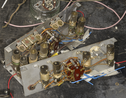
'Coil-Box' removed.
With all the 'coil-box' sections removed, it was then relatively easy to replace the resistors and paper capacitors. The wiring itself appears haphazard, and it becomes obvious that Hallicrafters definitely did not expect their radios to become collector's items. Take a look at the various manuals available on-line. The location of key components for aligning the receiver is given, but note that the PSU, audio and IF sections have been masked off to allow for annotations to be added relating to components in the 'Coil-Box'. I eventually found a Japanese website with several hand-drawn sketches, one of which helped me identify most of the components in the IF stages.
Regarding the wiring; The lacing 'string' was carefully cut away and I systematically replaced all the wiring; making sure that each wire was first marked with the same unique identifier at each end. Also, I take many high-resolution photographs, from various angles as I work. This gives me the opportunity to look 'back' if I am in any way unsure about something.
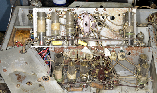
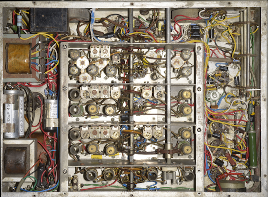
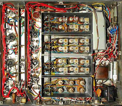
Above: A couple of photographs showing the shocking state of the metalwork and just how difficult it is to remove the coil-box sections.
Re-assembly of the coil-box is understandably tricky, with the rear section proving most troublesome. However, once it was all back together, there was only one wiring error (in the HF Osc. section), which was quite a relief. Although it did take a couple of days to track it down. I fully understand why such switches make use of 'shaped' wipers (makes for simpler wiring), but the practice does make understanding the circuit difficult at times.
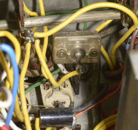
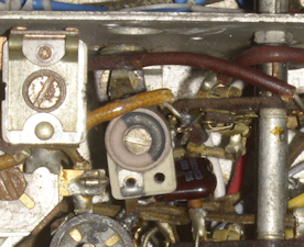
The (almost) 455KHz Crystal.
So, with the coil-box back together, it was time to focus on the IF section. This is a relatively straight-forward design ... similar in a couple of ways to that in the Marconi CR100. Both receivers provide switchable bandwidths, and both make use of a quartz crystal to provide the narrow bandwidths. See the photograph on the right. I initially mistook the crystal for an enclosed compression trimmer capacitor that appeared to have had some close calls with a hot soldering iron. As with the CR100, the method in the manual for aligning this part of the circuit is somewhat tedious on account that it dates from a time when test equipment was limited. In fact, in the 1940s you would be hard pressed to find an oscilloscope in a radio tech's workshop, let alone one with a useable bandwidth. Nowadays some of us are fortunate to have network analysers and spectrum analysers with tracking generators which make short work of aligning primitive crystal filters.
The alignment procedure in the manual starts with describing how to identify the crystal's actual frequency. It then struck me that this was probably the most important part of aligning the IF stages ... after all, the crystal itself is not adjustable, so it makes perfect sense to align the IF stages to the exact crystal frequency. This one turned out to be 453.166KHz. I used my Rigol DSA815 to glean this information.
Breaking it down, the IF section embodies the following ...
Two IF amplifier stages, V5 (6L7) and V6 (6SK7), two AVC (AGC) generators, V7 and V8 (both 6B8). As previously said, once the exact frequency of the crystal has been identified, T5 and T6 can then be aligned. The manual does not specifically identify the two AGC systems other than to say how the function is split. AGC derived from V7 (6B8) is applied to the IF stages, whilst the AGC derived from V8 (6B8) is applied to the two RF stages, V1 (6AB7, or 6SK7 in early models) and V2 (6SK7). V9 (6AB7) and one half of V10 (6H6) form the Noise Limiter or ANL. I think its a bit presumptuous to call it an Automatic Noise Limiter since it is very much a manually operated control. Like all noise limiters of that time, the ANL just appears to distort the signal. Maybe ANLs were intended to reduce pulsed interference like vehicle ignition spikes? One half of V10 (6H6) produces the ANL output which is applied to grid-3 of V5 (6L7). The other half of V10 is the AM detector, the output of which is applied to the first AF stage, V12 (6SC7).
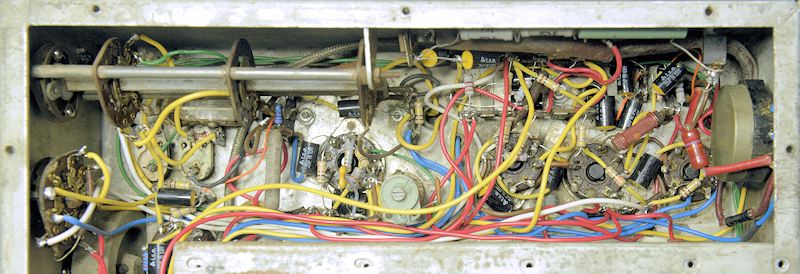
IF stages etc. before tidy-up.
With reference to the above photograph, one thing is evident ... this SX-28 has definitely been worked on. There is an abundance of British-Made components in there. The three resistors at the top, making up R31 (11K) and R32 (4K) look too new, with R31 being made up of two 5K6 wire-wound resistors from Radio Spares. One of the 5K6 resistors and the 4K wire-wound resistor were found to be open-circuit. This combination was replaced with R31 again comprising two 5K6 vitreous-enamelled wire-wounds and R32 comprising 10K in parallel with 6K8 (both vitreous enamelled wire-wounds). There was no obvious explanation as to why both R31 and R32 had been replaced, and why their replacements had failed
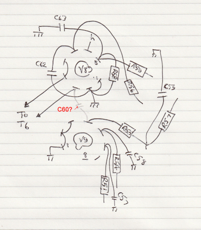
Placement of C60.
The S-meter adjustment potentiometer (R29), which according to on-line articles, is known to be 'problematic' had been replaced with one bearing an Air Ministry stores reference. R27 and R30 both appear to have been replaced with more modern resistors. Also, over towards the left in the photograph is a grey wire-wound 5K resistor, clearly marked as British Made ... this is R71 which is in the Anode circuit of the HF Oscillator, V4.
One on-line SX-28 resource which I found acknowledges that one is very likely to encounter instances where the hardware doesn't match the schematic. The placement of C60 is one such instance. In this case it is wired between V8 pin 3 and V9 pin 4, in line with very early SX-28s. In later models (including the SX-28A), it is wired between V9 pin 4 and the junction of C61 and T1 primary. However, this particular SX-28 also sports R6, R47 and C70 in the Anode circuit of V4, in line with not so early versions of the receiver. As the article stated, Hallicrafters had a policy of on-going improvements. However, for obvious reasons, the publication of the manual lagged behind a bit when it came to keeping up with design changes.
Note the carbon-rod resistor on the right. This is R51 (20K/1W). I opted not to replace it since it was well within specifications, wasn't showing any signs of stress, and if I were to replace it, I would have to use two 10K resistors in series.
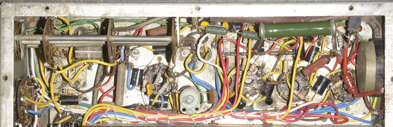
IF stages etc. tidied up, with replacements for R31 and R32 fitted.
Along with V6, V7 and V12, the BFO, v11 (6J5) is jammed into the area between the coil-box and the front of the chassis. It is fair to say that this is probably the most difficult area to work in. C72 provides the coupling between the BFO and the detector. In the manual the value is given as 2pF. However there is no such capacitor fitted. Instead, Hallicrafters used what is commonly known as a 'gimmick' in the form of an insulated wire wound a couple of times around the link between pins 4 and 5 on V7. This may have worked in 1941, with the wire that was used at the time. However modern solid-core mil-spec ptfe-insulated wire didn't 'cut the mustard'. The level of BFO injection was pitiful, so I fitted a genuine 2.2pF silvered-mica capacitor with far better results.
The area immediately behind the front panel.
Alignment of the IF stages and ANL were relatively straight-forward, aided for the most part by the tracking-generator feature on my Rigol DSA-815. I would like to point out here that other relatively low cost alternatives can be used for this purpose. I have previously used my DG8SAQ VNWA for aligning the filters in the Racal RA17 etc., and I can see no reason why a NANO VNA cannot be used in the same way. WARNING! ... Always use a suitable isolating capacitor on each cable when connecting them to your valve receiver ... failure to do so can be both expensive and embarrassing.
As can be seen from some of these photographs, I have attempted to tidy up the wiring using wax-impregnated lacing cord, as I have done with all the R1155s that I have refurbished. This is where the depth of the SX-28 chassis really does give you grief. Thus I have to confess that I am not happy with the lacing job.
It would have been nice to say that after a gruelling seven-month project, this SX-28 worked first time. Sadly, it didn't ... but it didn't go BANG! either. Due to a missing wire between V4 and SW8, the HF Oscillator mysteriously only ran on one band, at the wrong frequency. With the wire fitted, the HF Osc. ran on all bands, but frequency tracking was proving impossible until I realised that I had the Band Spread set to 0 when it should have been set to 100 ... oops!
I was getting there. But frequency-tracking was just not quite right. The SX-28 has these things called pads (C7 thru' C12 on the schematic) between the oscillator tank circuits (C98 thru' C103 in conjunction with T25 thru' T30) and the tuning capacitors (C1 thru' C5) which SW8-13 is used to select in combinations ... and then there's C13 for which there is no value given, other than it is a low value compression trimmer for temperature compensation reasons ... hmmm?
The manual is very clear when it states that the 'pads', which are themselves compression trimmers, should NOT be 'touched'. However, given the level of corrosion in this receiver, I felt it necessary to measure each pad in turn. To be fair, the items list gives each pad a nominal value. However only one was anywhere near its nominal value. Clearly these were factory-set components ... but a lot of water had gone under the bridge since 1941 ... and by the looks of things, much water had also washed over this SX-28.
So, these pads are in series with whatever combination of variable capacitors is selected by SW8-13. Thus, the inclusion of the pad limits (reduces) the actual range of variable capacitance. I have to conclude that his is either genius or madness! Eventually I managed to get five out of the six bands to track. Granted I did find it necessary to tweak a couple of the pads to 'nudge' the tracking a bit.
The only band that simply wouldn't track was the highest band ... and probably for good reason too. Pad C7 looked in very bad condition and C103 was a beehive trimmer mounted on the outside of the coil-box with a not insignificant length of wire snaking through a hole to one end of T30. I replaced C7 with a high spec 2000pF silvered mica capacitor, but setting the high end of the band always resulted in C103 (2 - 10pF) being set to minimum value ... and for a beehive, that means the two halves literally fall apart! I suspected the length of wire was contributing to the problem. Having replaced the old C7 pad with a much smaller, albeit fixed capacitor, I was able to shoe-horn a small ceramic trimmer into the compartment. BINGO! The top range now tracked!
On the left: A close-up of my ceramic C103 with the fixed value silvered-mica C7 underneath it. No snaking wires to upset the resonance.
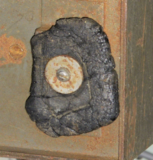
On the right: This is what happens to rubber feet stored in a damp shed (maybe) for decades. They become petrified ... literally. Looks like someone used liquorice to make the feet!
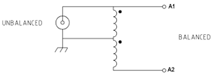
4:1 balun connections
Band 1 .... 800KHz ..... 25dB
Band 2 .... 1.6MHz ..... 24dB
Band 3 .... 4.0MHz ..... 20dB
Band 4 .... 7.0MHz ..... 24dB
Band 5 .... 14.0MHz ... 20dB
Band 6 .... 28.0MHz ... 22dB
As a communications receiver designed in 1940, many years before Single-Sideband was a thing, the SX-28 is a lovely receiver for listening to AM broadcast stations. For listening to CW stations, the BFO does exactly what it is designed to do, and the generous range of IF bandwidths come in very useful. When it comes to SSB, the SX-28 can produce reasonable quality, but you definitely need to 'ride' the RF gain control in order to not overload the simple detector.
There is also an underlying very low-level hum present which is totally independent of audio gain level. I did some research on the matter ... i.e. I googled 'SX-28 hum'. And, it turns out its a thing! There are more than a few discussions on-line regarding the issue. Investigating the issue, I concluded that the hum was indeed mains-hum ... i.e. 50Hz (UK Mains). Now, since the 5Z3 is a full wave rectifier, any AC ripple on the B+ line would be 100Hz. So that rules out an issue with the smoothing pack. Several of the on-line discussions come to the same conclusion, that the hum is not electrical pick-up but actually electro-magnetically induced, with the massive mains transformer being the source. Because of its proximity to the mains transformer, the audio transformer actually picks up the induced field, albeit small and transfers it to the loudspeaker or headphones ... and since it is post AF-Gain control, it is a constant level. This also explains why when you switch on your SX-28, you get a loud hum from the speaker almost immediately, before the valves have heated up. This then fades away before coming back as a very low level hum. Note that in the SX-28, the mains transformer, smoothing choke and audio transformer are all aligned on the same plane, so it isn't surprising that there is some electromagnetic coupling.
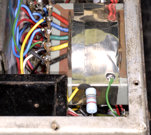
Grounded shield.
The reason why you don't get this issue with the RA17 etc. is because the mains transformer, smoothing choke and audio transformers are ALL encased in grounded metal enclosures ... i.e. magnetically screened. So I fashioned a shield from conductive tin tape by wrapping it around the audio transformer and grounding it to the chassis. Obviously not perfect, but there is a reduction in the level of hum.
It is actually good practice to always use closely matched 6V6s in the SX-28. I found that one of the output pair was giving a much lower gain than the other, so I changed it for one with a higher gain and the level of hum actually reduced significantly. The reason why this might be so is because the centre-tap on the audio transformer primary can be considered a virtual earth ... I think.