Not a 23cm PA!
7 minute read
March - April 2008
Some time ago ... Round about 1998, Motorola developed the MRF20060R, specifically I assume for the mobile ‘phone market. Not that they were advocating ‘Cell-Phones’ with an output of 60W though! Given that the specified operating frequency is 1.8GHz - 2GHz, I would guess that this device was more than likely developed for use in local ‘cell’ transmitters. If you search hard enough on the Internet you might just find one reference to the use of this device on 23cm, and for a small sum of money you might even be able to obtain a modified PA originally manufactured by Lucent, which, it is suggested will give 60W on 23cm for around 10W drive. This was an attractive proposition to a friend of mine, and he promptly bought one.
But it was not to be ... For within a matter of minutes, the PA device, the afore mentioned MRF20060R had popped! The supplier very kindly dispatched a replacement device at no extra cost, but my friend was not surprisingly cautious about simply changing the device. To cut a long story short, he eventually went down the valve route and now runs an air-cooled 2C39BA PA on 23cm. He gave the Lucent PA to me for investigation and hopefully repair ... and if I could get it working, then I’d have myself at least 50W on 23cm.
But it was not to be ... For within a matter of minutes, the PA device, the afore mentioned MRF20060R had popped! The supplier very kindly dispatched a replacement device at no extra cost, but my friend was not surprisingly cautious about simply changing the device. To cut a long story short, he eventually went down the valve route and now runs an air-cooled 2C39BA PA on 23cm. He gave the Lucent PA to me for investigation and hopefully repair ... and if I could get it working, then I’d have myself at least 50W on 23cm.
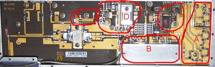
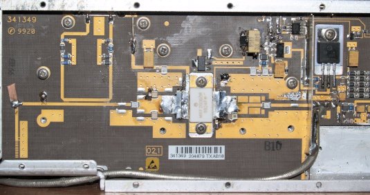
Lucent PA Board
I too, was not about to simply change the device without caution. The first thing you notice about the PA is that most of the circuitry appears to be associated with a driver module (possibly Mitsibishi?) conspicuous by it’s absence. I therefore set about the task of reverse engineering the amplifier by working out the circuit diagram from what I could see.
Area ‘A’ is very obviously a programmable attenuator network.
Area ‘B’ is very obviously where the driver ‘brick’ would sit.
Area ‘C’ is apparently an electronic (programmable) potentiometer. The smaller of the two chips is an EEPROM.
Area ‘D’ is the bias supply for the MRF20060R and might be described as a bit of an enigma!
Area ‘E’ will be revealed later!
Having worked out the bias supply circuit, which is derived from a 5V supply, I fitted the replacement MRF20060R, and whilst monitoring the Base voltage and Collector current, I slowly increased the bulk supply. What I witnessed had me alarmed. I was informed that the on-board bias supply was intended to produce a voltage at the Base of around 0.75V (not necessarily precisely) which would supposedly incur a Collector current of 200mA for a Collector voltage of 24V. However, long before the bulk supply reached 24V, the Collector current was already in excess of 200mA and rising. I switched it off. Something was not right. It didn’t take me long to come to the conclusion that something was lacking in the control of the bias voltage. Closer examination of the bias supply circuit lead me to the conclusion that there was absolutely no thermal compensation for a start. Although there does appear to be a thermistor in contact with the heat-sink, it is NOT connected to anything, instead it goes to two pins on an ‘unused’ connector. Similarly, the electronic potentiometer ‘C’ is connected to the bias supply ‘D’, but the control lines, like the thermistor are connected to the ‘unused’ connector. In conclusion, in the absence of the appropriate circuitry that would normally be connected to the ‘unused’ connector, the bias supply is effectively open loop. If there is any thermal compensation, it is the wrong way round . . . That is, heating the board actually incurs an increase in the voltage on the Base of the MRF20060R.
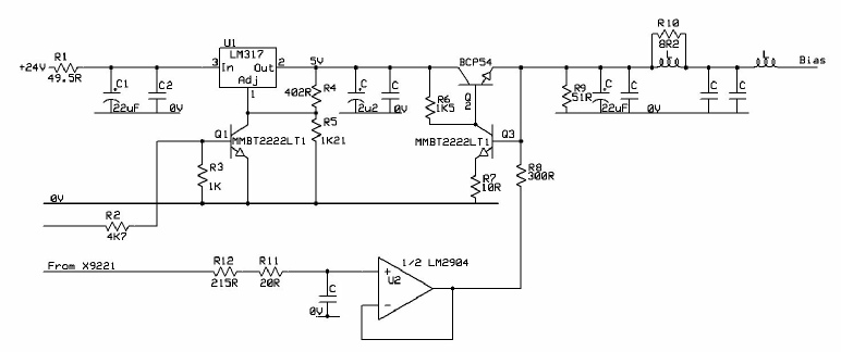
Lucent PA Board, original bias supply
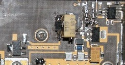
So having concluded that correct operation of the bias supply and implementation of thermal compensation is dependent on external and unavailable circuitry, I turned to the MRF20060R data sheet for clues as to how else to control the device. Fortunately the MRF20060R was conceived as a linear device and the data sheet includes a test circuit with an appropriate yet simple bias supply. Interestingly, the tracks and pads in Area ‘E’ (see earlier photograph) satisfy Motorola’s bias supply with a surface mount PNP power transistor adjacent to the PA device providing the appropriate thermal feedback.
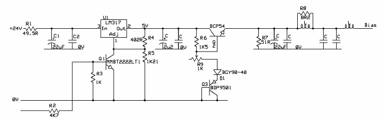
Lucent PA Board, modified bias supply
Q3, BDP9501 provides the obvious P-N voltage as well as the necessary negative thermal compensation. D1, BGY90-40 is a schottky diode and thus adds a (smaller but necessary) further P-N voltage whilst R9 provides some safe degree of control over the final bias voltage ... See below ... And it works!
MRF20060R (Lucent) - modified
Time is no respecter of persons, and towards the end of March I reached the big ‘five-oh’, celebrating the event with a holiday. On return there were several non-radio matters requiring my attention, so work on the Lucent PA was put on hold. When the time came to continue with the PA, I verified that the bias was stable at 200mA and connected it up to my 23cm transverter, having first reduced the output to 3W. With 24V on the PA, I applied RF drive, expecting to see something like 30W. But instead I was lucky if I was getting more than 10W out. Slowly, I increased the drive, carefully watching the Collector current for signs of instability and/or saturation. I increased the drive until it reached 10W (maximum permissible drive), at which point the PA output had reached a mere 45W for a Collector current of 5.5A. I had been told that the Collector current should not exceed 6A and that for such, the output should be at least 60W for a maximum drive level of 10W. Yet I was lucky if I was seeing 45W. Still, it was amplifying, that was something ... and it was achieving 33% efficiency. I held carrier for about 30 seconds and was pleased to see that the device was stable ... no tell-tale creeping up of Collector current. I dropped carrier and the collector current dropped back to 200mA. Despite the low(ish) power, I was more or less happy. I re-asserted carrier and was conscious of a little flash of light and the fan on the heat-sink stopped turning ... The Collector current now read 0mA. The MRF20060R had popped! But why? Back to the data sheet ...
It was then that I saw it. I knew that the MRF20060R was intended for operation at 1.9GHz, but it was clear that at lower frequencies, the projected gain was going to be considerably lower, the Collector efficiency somewhat lower and internal VSWR higher. Everything pointed to this NOT being a suitable device for use at 1.3GHz. In fact nowhere in Motorola’s data sheet is there any hint that the device can be operated below 1.8GHz. In hind sight, I can only surmise that the internal construction of the MRF20060R renders it entirely unsuitable for use at 1.3GHz, which is probably why there are NO articles on the Internet detailing it’s use on that band.
One final thought ... If it wasn’t so easy to obtain Spectrian boards using the Motorola XRF286S, it might just be viable to modify this PA for use at 2.3GHz.