A GPS Disciplined OCXO
4 minute read
May 2007
Back in 1979 when I started work for Racal, ‘we’ had a newly acquired Hewlett-Packard microwave counter, against which all the other EIP counters were calibrated. However, the HP counter had to be sent to NPL once a year for calibration and when it returned the only guarantee was that it had met certain specifications immediately prior to dispatch. How times change!
Something that has been cause for serious debate is ‘how does one go about verifying one’s frequency at 2.3GHz or 3.4GHz and above?’ Now, if you live in the South of England, the answer is easy ... Simply set the LO and prime-mover combination against a known beacon! Not so easy up hear in Scotland! At the last count (May 2007) we had three 23cm beacons and one 9cm personal beacon. However the latter beams SE and is only heard via rain scatter at my QTH. There are sadly no 13cm beacons currently running in Scotland. The problem with measuring LO frequencies is that most affordable frequency counters only work up to 1.5GHz. The obvious alternative to constructing a pre-scaler is to measure the frequency of the ‘fundamental’ ... that which the crystal was cut for. For a 13cm transverter, this will likely be 120.8889MHz and for a 9cm transverter, 135.6667MHz. Both of these frequencies easily fall within the scope of simple frequency counters. However, place even a probe tip close to the oscillator and you will introduce a loading effect, usually shifting the frequency by at least 100Hz for example. This is where today’s breed of general coverage receivers come to the rescue. A few years ago I acquired an Icom 706MK2 which has reasonably good RX performance at 135MHz. I needed something accurate and local with which to verify the accuracy of the 706 or at least to identify any offset that would need to be included in the equation. The idea was to monitor the 135MHz oscillator on the 706, set to USB and feed the recovered audio into Spectran. The 706 is set to read 1KHz LF at 135.665666MHz +/- any known offset (-9Hz in my case). The LO is then adjusted for a 1KHz trace on Spectran. But first, the accuracy of the 706 (or whatever) must be ascertained. This is done with the aid of a low-cost 10MHz ‘standard’.
To quote James Miller, G3RUH, ‘A well kept secret of the Rockwell/Conexant/Navman Jupiter GPS engines is that they have a 10 kHz output, synchronised to GPS time. So, with a few additional components you can phase lock a 10 MHz VCXO to the 10 kHz, and you then have a simple lo-cost frequency standard with remarkable performance.’
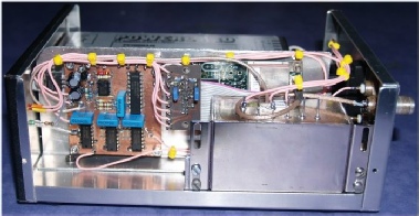
I also made a small ‘daughter board’, clearly visible in the centre, which mates with the 20-pin header on the Jupiter board.
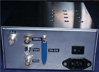
The photograph on the right shows the rear panel of the GPS box. The ventilation holes in the lid are necessary as are those in the base since a considerable amount of heat is generated by the PSU, OCXO and Jupiter board. Even with the holes, the temperature inside the box reaches 40 Celcius! The antenna for the GPS is an active PCB type by Conifer mounted on a pole outside. Unfortunately my one was dead on arrival but I managed to remove the brass cover and replace the GaAsFET with one from stock, and it appears to work fine now. The RS-232 port interfaces with one of my many PCs which runs VisualGPS. This is an ideal free application with which to test the Jupiter board. However an amusing feature of this whole setup is that if the GPS receiver is running and the box is connected to the PC when the PC boots, Windows XP will detect the interface board as a ‘pointing device’ or ‘pen mouse’ to the effect that the mouse goes ballistic.