Yet another resurrected R1155
17 minute read
April 2022
Number 11 ...
I was surprised to discover that this is at least my 11th R1155 restoration. I have found some photographs of two R1155Fs in my archives, but no record of any work being carried out ... so I may have done as many as thirteen so far. Anyway, This particular R1155B proved to be both interesting and challenging ...
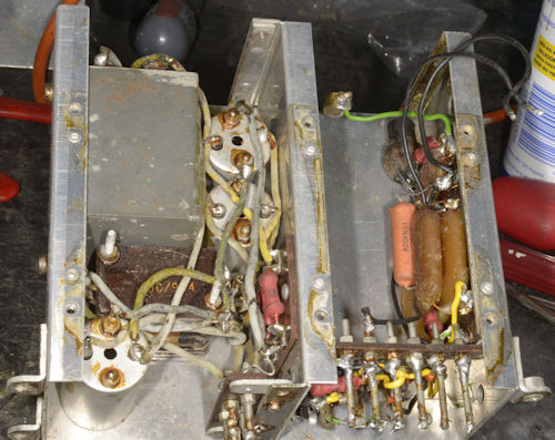
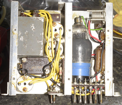
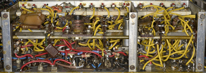
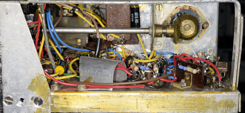
Above: Before and after views of the BFO/DF compartment. Given that trimmer capacitor C13 had been removed and replaced with a variable version, I would venture that the bright yellow wiring and the orange capacitor in the photograph on the left are the work of a post-services owner. The orange capacitor is a replacement for the stud-mounted C120 (100nF). The wiring in the DF compartment is in a very poor state. The block capacitor (C3,C4 and C5) was 'disembowelled' and subsequently re-stuffed with modern polypropelene capacitors. While disassembled, it is a very wise to check the integrity of the stack of capacitors comprising C20, C22, C21, C107 and C18; replacing any that are faulty before rewiring. The BFO can easily be tested on the bench whilst the wiring in the DF compatment can be verified by checking various resistances between the bottom and top sets of pins.
The next task is to strip down the infamous Coil-Box, replacing any faulty and/or missing components ...
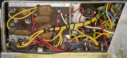
A couple of close-ups of the lacing around the visual indicator (left) and the meter-control potentiometers (right). Since the Meter-Balance control was already missing, I fitted a new 22K Linear potentiometer. Historically this is a peculiar component since the wiper terminal is physically connected to the outer body of the control, and thus earthed. This isn't a problem since the wiring also connects the wiper to ground by two wires anyway. Failure of the Meter-Amplitude potentiometer during testing necessitated replacing it also ... another 22K Linear Pot.
I was surprised to discover that this is at least my 11th R1155 restoration. I have found some photographs of two R1155Fs in my archives, but no record of any work being carried out ... so I may have done as many as thirteen so far. Anyway, This particular R1155B proved to be both interesting and challenging ...
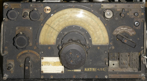
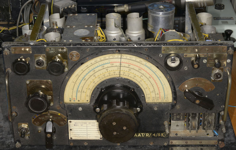
A rather sorry and grubby looking R1155B
Of the three 1155s awaiting restoration, I deliberately chose this one since it had a full compliment of screw-on labels, although the round one for the Hetrodyne Adjustment appears to be different. The BFO trimmer had been removed from the BFO compartment and changed to one with a shaft which had been fitted in place of the Meter Balance control. There was no lid on the BFO/DF compartment, as was there no Coil-Box cover. All three of the DF valves were missing and a 6V6 audio amplifier stage had been fitted where one of the missing VR99As would have been. The two wave-wound inductors making up L24 were present as was the DF oscillator transformer L23, although one of the windings in this was later found to be open-circuit. All of the tall tubular chassis-mounted capacitors had been removed as well as C93 (4uF). As expected, the rubber-insulated wiring was in a shocking state.
Sourcing enough parts from the two donor chassis that I had been given, and from my own stock of spares, I set about 'gutting' this R1155. Although the serial plate clearly states that it is an R1155B, with RAF stores reference 10D/13045, it did not have any of the HF chokes that were fitted to minimise radar interference. The serial number of ATL1068 is also unusual, making me think that this receiver might not have been destined for installation in a bomber. Then there's the lettering 'AAT/R/4/58' which I know indicates that it was refurbished in the fourth week of 1958 by a workshop identified by the initials AAT. Although I have been unable to identify who of where AAT was. Are ATL and ATT connected in any way perhaps? Had the HF chokes been removed in 1958? The Mod plate to the left of the tuning mechanism does indicate two jobs carried out on January 30th 1958, although the modification record for the second one has been deliberately scratched out ... interesting.
Sourcing enough parts from the two donor chassis that I had been given, and from my own stock of spares, I set about 'gutting' this R1155. Although the serial plate clearly states that it is an R1155B, with RAF stores reference 10D/13045, it did not have any of the HF chokes that were fitted to minimise radar interference. The serial number of ATL1068 is also unusual, making me think that this receiver might not have been destined for installation in a bomber. Then there's the lettering 'AAT/R/4/58' which I know indicates that it was refurbished in the fourth week of 1958 by a workshop identified by the initials AAT. Although I have been unable to identify who of where AAT was. Are ATL and ATT connected in any way perhaps? Had the HF chokes been removed in 1958? The Mod plate to the left of the tuning mechanism does indicate two jobs carried out on January 30th 1958, although the modification record for the second one has been deliberately scratched out ... interesting.
The dismantling process involves removing everything from the chassis and storing all the bits in labelled poly bags. This time though, I opted not to remove the valve bases, deciding to clean them in-situ. At this point, I noticed that the solder-tag for pin 8 of V9 (VR102) had been snapped off completely ... probably the reason why that socket was not being used for the 6V6! C103 doesn't really need to be removed from the front panel so I left it in place. Likewise, I opted not to remove C56, the large trimmer capacitor adjacent to the Master Switch. Now is a good time to remove and replace all the rubber grommets. Rubber was a 'premium' back in 1940, so in many cases the grommets were made of a brown synthetic compound which, over time, will have become a brittle sugar-like ring. Some of the genuine rubbers grommets will have become as hard as glass. I have even encountered a few white rubber ones. These appear to have fared the best over time.
Sadly all but two of the valves turned out to be useless. Only V7 in the BFO and the Magic Eye V10 were the correct type. All the rest were either CV1053s, CV1057s or similar ... all with the metalised outer coating flaking away. When tested, all but one of them proved to be very poor in the gain department. Turning to the two donor chassis, I pulled all the valves and luckily managed to put together a set of 'correct' valves that worked. Although I did find a couple of KTW63s ... similar to the VR100/KTW62, but lower gain ... And an MHLD6 with a big chunk of glass rolling about inside ... it worked, but I wasn't going to chance it!
Sadly all but two of the valves turned out to be useless. Only V7 in the BFO and the Magic Eye V10 were the correct type. All the rest were either CV1053s, CV1057s or similar ... all with the metalised outer coating flaking away. When tested, all but one of them proved to be very poor in the gain department. Turning to the two donor chassis, I pulled all the valves and luckily managed to put together a set of 'correct' valves that worked. Although I did find a couple of KTW63s ... similar to the VR100/KTW62, but lower gain ... And an MHLD6 with a big chunk of glass rolling about inside ... it worked, but I wasn't going to chance it!
BFO/DF compartment, as found.
BFO/DF compartment, refurbished ... with trimmer C13 re-fitted.
Above: Before and after views of the BFO/DF compartment. Given that trimmer capacitor C13 had been removed and replaced with a variable version, I would venture that the bright yellow wiring and the orange capacitor in the photograph on the left are the work of a post-services owner. The orange capacitor is a replacement for the stud-mounted C120 (100nF). The wiring in the DF compartment is in a very poor state. The block capacitor (C3,C4 and C5) was 'disembowelled' and subsequently re-stuffed with modern polypropelene capacitors. While disassembled, it is a very wise to check the integrity of the stack of capacitors comprising C20, C22, C21, C107 and C18; replacing any that are faulty before rewiring. The BFO can easily be tested on the bench whilst the wiring in the DF compatment can be verified by checking various resistances between the bottom and top sets of pins.
The next task is to strip down the infamous Coil-Box, replacing any faulty and/or missing components ...
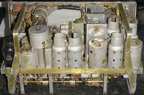
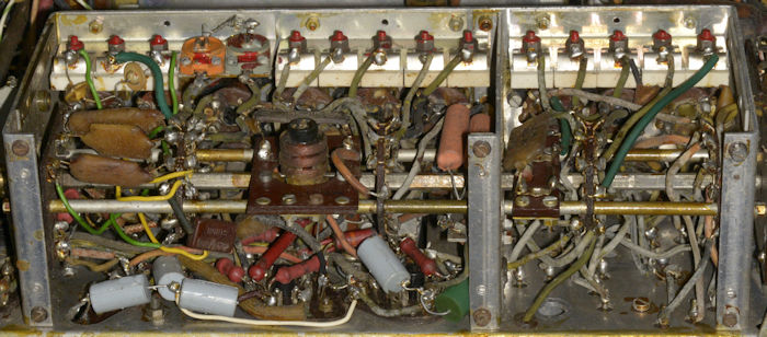
The Coil-Box, prior to removal.
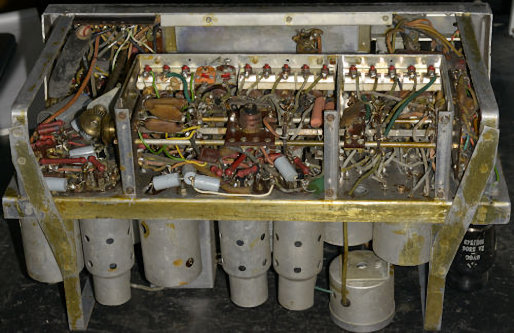
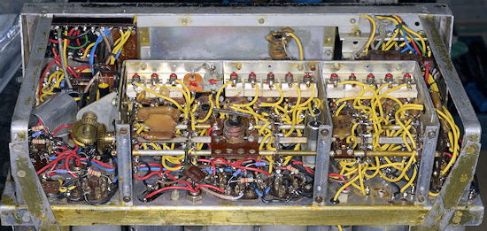
Definitely some repair-work in the Oscillator area (left), whilst the four stud-mounted 100nF capacitors (C40, C37, C38 and C34) had all been removed and replaced with wire-ended capacitors. Note the five other 'new' capacitors replacing two of the tall iconic chassis-mounted cans.
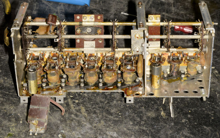
The Coil-Box, devoid of wiring.
A word of caution ... Not all Coil-Box switches are alike. Some builds have been found NOT to have built-in end-stops. This can cause nightmarish hair-pulling frustration if you forget which position the band-switch was in when you disconnected the bevel gears. ALWAYS centre the switch on band 3 when removing the Coil-Box. Obviously you need to remember this when re-fitting ... duh!
The Coil-Box is secured to the main chassis by four 4BA studs and three 6BA nuts. Care should be exercised when undoing the 4BA nuts (clearly visible in the photograph above) as the studs are actually quite soft. In my case, the two on the right snapped and I had to pop-rivet replacements into place.
With all the wiring carefully removed (some of the tags on the inductors can be fragile), verify the integrity of all the windings. Next, it is wise to 'free up' all the soft-iron ferrite cores. Marconi, or whoever built the assembly will likely have used a generous amount of shellac varnish, so a hair-dryer or in my case, a heat-gun will be necessary to soften the varnish first, in order to start carefully moving the cores. ALWAYS use the correct size of tool otherwise the slot can be damaged and the core will crack and sheer. It might also be a good idea to clean out the white chalky grease that is used as a lubricant/binding. I have found that a standard M8 tap fits nicely, and can be run through the empty former to clear it of debris. The cores in this particular Coil-Box had not been treated with respect and a total of five cores required replacing and a sixth could not be shifted at all, so I was forced to replace the coil-former assembly with one from an appropriatley identical Coil-Box. Note that the Coil-Box coils in an R1155 L or N are NOT in the same order as those in other models. All four of the stud-mounted capacitors are back on the assembly.
Finally: Note the two capacitors folded down on the left. These are C76 and C77. The earthy end of C76 was found to be broken off, so the pair of capacitors was replaced with a pair from a scrapped Coil-Box. It is best to leave these two capacitors out until the re-wiring of the box is complete.
The Coil-Box, re-wired (and re-fitted).
Above: I didn't take a photograph of the Coil-Box before re-fitting it to the chassis, so here's one of it in place on the finished receiver. It's not a mess, it's a piece of art!
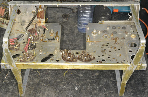
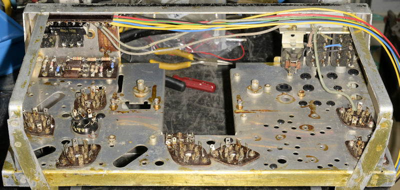
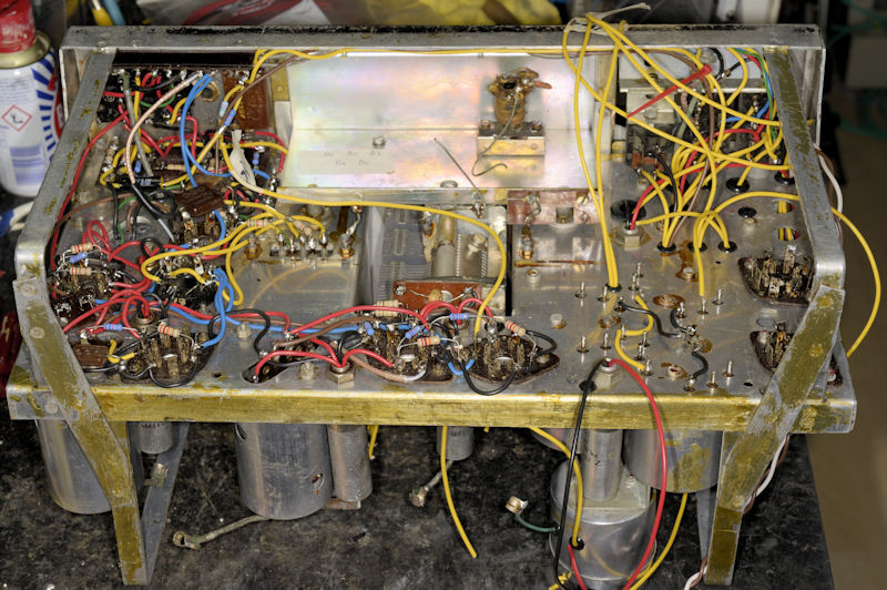
Re-building starts.
Re-building can now begin in ernest. The photograph above shows all the chassis-mounted parts along with the under-chassis front-panel parts. The wiring in the picture is generally that which connects the 9-way distribution tag-board to the 'Jones-Panel' ... although some of the wires go as far as the Master-Switch. This bundle of wires forms part of what might be called the 'bottom channel' once the receiver is fully assembled. The bias-board is on the left and forms a crucial part of the receiver, providing the necessary resistances which in turn interact with the rest of the circuitry to produce the negative bias rail. The HT supply in the R1155 'floats' ... i.e. the HT supply is connected between pins 8 and 5 of P1 in the Jones panel, whilst pin 4 is connected to the chassis. Thus pin 5 becomes negative with respect to pin 4.
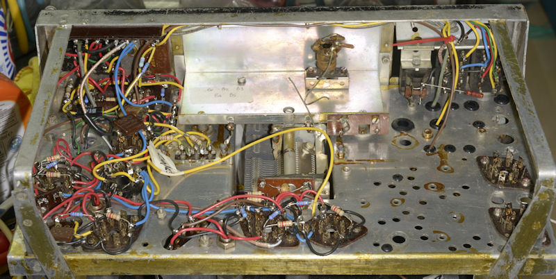
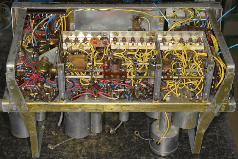
Ready for the Coil-Box ... almost.
Above: This is the bit that I really enjoy. It gives a real sense of progress. Although this one had me scratching my head ... something didn't look right. There are three IF-Transformers in the R1155; L19, L20 and L21. L19 and L20 are identical ... electrically. However they have different Stores numbers ... 10K/12136 and 10K/251 respectively. In the picture above, work generally commences top left and progresses anti-clockwise. I had fitted L20 (bottom left) and had moved on to L19. Both of these, and L21 had previously been re-furbished, i.e. I had replaced any resistors inside and cleaned the aluminium cans. When I fitted L19, something looked odd. Below the chassis, all was fine, but something was not right with the grid-lead attached to the top of the assembly ... it was wrongly orientated for connection to V5 top-cap. The initial thought might be that the assembly had been mounted 180 degrees out. But that isn't possible since the board is slightly offset. And I had definitely not mixed up L19 and L20. The Stores numbers on the top of each assembly agreed with the items list. I discovered that at some point in time, someone had replaced the board in L19 with one from an L20. Electrically they are identical but mechanically they are very slightly different with the top two terminals swapped. It had taken me no less than ten R1155s to actually note this fact ... hmmm? I then remembered that I had replaced the grid lead on the top of L19 because the 'original' had been damaged. Long since chucked in the bin (after retaining the top cap) I cannot confirm if it was slightly longer and was thus able to reach the top of V5. An interesting diversion none the less.
The blue wires are the heater supply. Brown is AGC, or AVC as it was called then. Black goes to chassis, red is HT and yellow is everything else. The resistor wired between two terminals on the Jones-Panel is simply there to simulate a 'yet to be fitted resistor' whilst making incremental resistance tests.
The blue wires are the heater supply. Brown is AGC, or AVC as it was called then. Black goes to chassis, red is HT and yellow is everything else. The resistor wired between two terminals on the Jones-Panel is simply there to simulate a 'yet to be fitted resistor' whilst making incremental resistance tests.
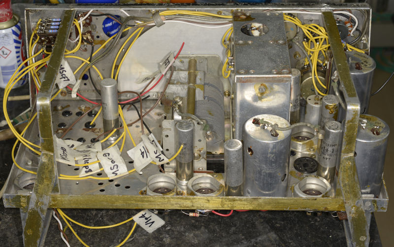
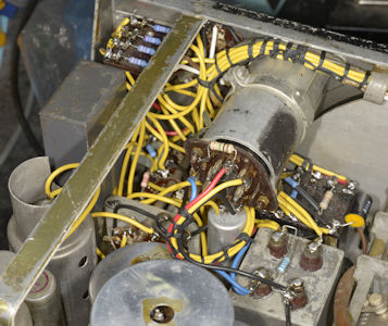
The real L19!.
Above: The above-chassis wiring looking decidedly messy as preperation for the dreaded Master-Switch nears. L19 is immediately behind (or in front of) the BFO/DF module. You can see how if the top two terminals were reversed, the lead would not reach V5 TC.
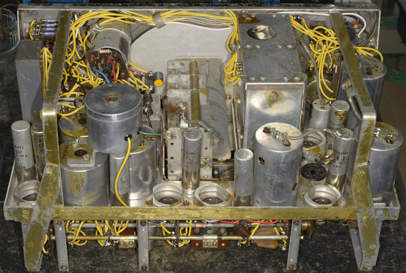
Now we're ready for the Coil-Box!
Above: Final prep for re-fitting the Coil-Box to the chassis. Once it is in place it is extremely difficult to access the components immediately under it, so a lot of wires have to be pre-cut, poked through holes and appropriately labelled.
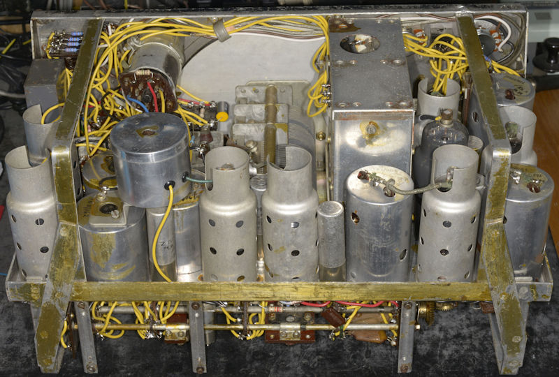
It fits!
Above: Always a satisfying moment ... when the Coil-Box is secured back down onto the chassis. In the photograph above, the two DF valves, V1 and V2 have also been wired. Cable-ties are used as temporary tidies until the wiring is laced authentically.
Almost there!
Above: It has to be said that at this point, the wiring behind the front panel looks anything but neat. Most of what you see there is associated with the Direction Finding circuitry and functionallity was more important than aesthetics ... after all, the R1155 was never designed to be maintained ... especially since the life of the bomber it was to be fitted in was typically measured in weeks. A sobering thought.
Time to test it!
I've never finished an R1155 restoration that resulted in smoke, and this one was no exception. All the wiring is meticulously checked, right down to ensuring that the correct coils are selected when the various bands are selected. Once statisfied that there are no obvious errors I connected up to my own T1154. The supply to the R1155 was controlled by the main switch on the T1154. Between this and the Jones Panel on the R1155, I insert a box which allows me to control the level of HT and monitor the volts and current ... safety first!
This one worked first time ... actually thay all have. But as expected nothing was in the correct place on the dial since all the variable inductors and capacitors in the Coil-Box needed to be properly aligned. What looks like a daunting prospect is actually relatively straight forward. The IF stages are aligned first, then the Local Oscillator and finally the RF stages.
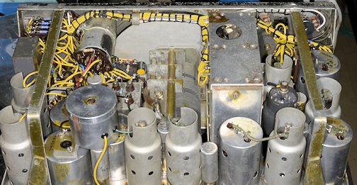
The photograph above shows a full complement of valves, including the DF valves. I didn't have any VR99As for V1 and V2, however I fitted a pair of CV1193s which are considered to be equivalent to the VR99, which itself is identical to the VR99A. It is believed that VR99As were simply matched pairs of VR99s supplied for the R1155. The VR102 that I fitted for test purposes is my personal spare.
This one worked first time ... actually thay all have. But as expected nothing was in the correct place on the dial since all the variable inductors and capacitors in the Coil-Box needed to be properly aligned. What looks like a daunting prospect is actually relatively straight forward. The IF stages are aligned first, then the Local Oscillator and finally the RF stages.
The photograph above shows a full complement of valves, including the DF valves. I didn't have any VR99As for V1 and V2, however I fitted a pair of CV1193s which are considered to be equivalent to the VR99, which itself is identical to the VR99A. It is believed that VR99As were simply matched pairs of VR99s supplied for the R1155. The VR102 that I fitted for test purposes is my personal spare.
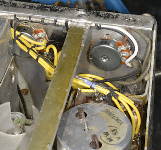
Having satisfied myself that this receiver more than meets Marconi's specification it was time to finalise the wiring in the traditional way. The two photographs above show the authentic waxed-cotton lacing behind the front panel.
A couple of close-ups of the lacing around the visual indicator (left) and the meter-control potentiometers (right). Since the Meter-Balance control was already missing, I fitted a new 22K Linear potentiometer. Historically this is a peculiar component since the wiper terminal is physically connected to the outer body of the control, and thus earthed. This isn't a problem since the wiring also connects the wiper to ground by two wires anyway. Failure of the Meter-Amplitude potentiometer during testing necessitated replacing it also ... another 22K Linear Pot.
Above: Two more views. This time, on the left, the area adjacent to the bevel geers, and on the right, the DF Tag-Board and the circuitry around V1 & V2. Note the two 'new' screws in the bottom left of the photograph on the left. I became aware of a subtle aberation in the top left of the front panel, where it appeared to have been pushed back slightly. This was odd since there was no evidence/aberation behind the front panel to back this up. In order to correct this bend in the front panel, it was necessary to drill out the spot welds in two places in order to pull the front panel back into shape. Once done, the welds were replaced with machine screws on the side and a pop-rivet on the top edge.
Finished!
Looking much smarter than when it arrived, here is the finished R1155B Serial Number ATL1068. Purists will flinch in horror at the sight of the polished brass labels. There are three types of control label found on R1155s. These fall into two categories, screw-ons and silk-screen. The latter are just that ... annotations silk-screened onto the textureless black front panel. Even the band-switch label on the R1155E was a coloured silk-screen! Earlier R1155s came with a textured (crackle-finish) front panel ... some more crackled than others. This one has a fine texture, but still textured. Some screw-on labels were white-on black where the black was actually black paint. These look good, and if in good condition, clean up well. The labels on this receiver look like a mix of embossing and anodising where the dark 'background' looks like a very dark brown (anodised?) and the annotation is very slightly raised and the colour of the original brass. Attempts to clean the lettering were less than mediocre. The only thing that had any effect was good old Brasso, but that had the inevitable effect of removing the anodising around the edges ... so I simply polished the labels down to the brass! Maybe not everybody's choice but they don't look too bad. The coloured dots on the band-switch label were touched up with acrylic paint.
The acetate blister polished up nicely with brasso. However the original dial-plate was too far gone ... faded and stained, so I replaced it with a spare, salvaged from a donor.
The acetate blister polished up nicely with brasso. However the original dial-plate was too far gone ... faded and stained, so I replaced it with a spare, salvaged from a donor.