Transverters re-built
7 minute read
Transverter upgrades... almost
November 2003
During August 2003 I began to take stock of ‘things’. Now well into the ‘doldrums’ of H.F propagation, I began to look for other inspiration and decided to drastically change my antenna configuration. Something inside me simply cannot abide the sight of antennas lying unused, especially when I have the equipment that goes on the other end of the coax. And besides, the Mini-Quad was looking decidedly lonely.
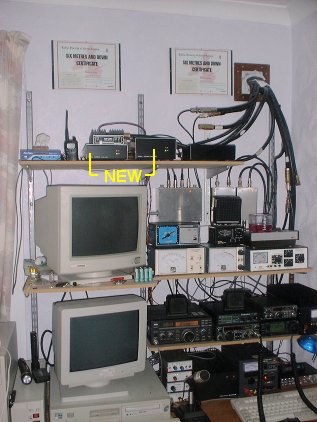
The first thing I did was to completely strip the antennas off the mast that is bolted to the gable on the South end of the house. The 23cm 35 ele Tonna was finally replaced by an extended ‘M-Squared’ 35 ele (now 43 ele). The 13cm 25 ele came down on account that the accompanying transverter was just NOT working, and the old 18 ele parabeam shifted up in its place, just leaving room, albeit not optimum spacing, for my now un-bent 8 ele Eagle for 2m at the bottom. Also present on this little mast are a UHF dipole for 70cm and a VHF dipole. As can be seen from the photograph below, there have been a few additions to the shack. I was fortunate to get a good deal on a second-hand ICOM 706MK2 which prompted me to resurrect my 6m 3-ele beam.
The 706 uses ALC to control the output power in such a way that even when low power is selected it will always initially output several milliseconds worth of full power. Because of this, I still use the IC260 to drive my 2m amplifier. It would have been convenient to use the 706 but I felt that with the MK2 capable of delivering 20W on 2m, it was simply not worth the risk of blowing the PA in the amplifier. Consequentially, the 2m output on the 706 is attached to the dipole on the gable end. The Trio TR-8400, on top of it is connected to the UHF dipole. Ideally this ‘wee’ radio would be used for connecting to the DX-Cluster, but since there ain’t such a thing here in central Scotland, it is used in conjunction with my VX-1 when doing antenna work. It is good to be able to speak to someone in the shack when making fine adjustments to antennas.
Finally, I have never been one to run from a challenge and after consigning the 13cm transverter to the ‘junk box’, I repented of my brash decision. I systematically tested all the active devices and came to the conclusion that the mixer was faulty and decided to replace it with a Mini-Circuits ADE-3G surface mount device. Fortunately only minor track changes were necessary, and the transverter burst into life and now delivers a good clean 1 Watt of power. With 13cm now a viable band, I needed a perch for the antenna. There were still two spare runs of 4-50 coax on the main mast and one of these was a single uninterrupted run of FSJ4-50B, all the way past the rotator and which had once fed my UHF colinear. Thus, the end-mounted 25 ele Tonna is now mounted on the main mast, half way between the 6m beam and the Mini-Quad. Now if I could just find someone to work on 13cm! . . . Hmmm?
I have long since adopted the principle that if something is working, it is best left alone, and if to be left alone, it should first be built to a standard such that it should also look good.
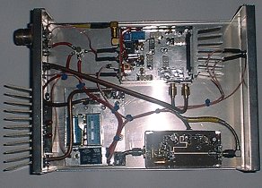
The 23cm transverter is based on DB6NT’s MK1 version as published in DUBUS 4/92. The only difference being that I employed a Mini-Circuits SAM-5 mixer of which I have many, instead of the Synergy SMD-C3 specified in the DUBUS article. As can be seen in the photograph, the basic transverter is tiny, measuring only 75mm by 55mm. On it’s own, the transverter delivers around 1.2W with very respectable receive performance. The overall performance is augmented by the inclusion of a GaAsFET pre-amp utilising an Avantek ATF-10135 (bottom right) and a 20W PA utilising a Mitsubishi M57762 power module (far left).
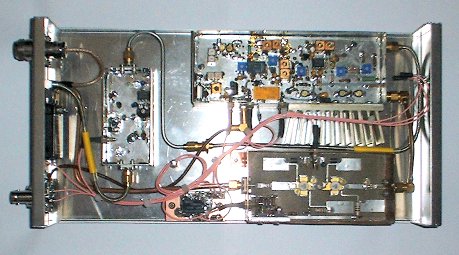
The 13cm transverter is a real mixture of technologies and has evolved as a result of availability, rather than necessity. The basic transverter (top) is based on DB6NT’s MK1 version as published in DUBUS 3/93. The only difference being that I employed a Mini-Circuits ADE-3G mixer, instead of the Synergy SMD-C3 specified in the DUBUS article. The PA (bottom) is from my original 13cm kit dating back to 1986 and uses bipolar devices in the form of a BFQ34 driving a BFQ68 delivering about 3W. The pre-amp (left) likewise, was also part of my original 13cm kit, but has been subsequently modified to be a no-tune affair employing an MGF4919 HEMT.
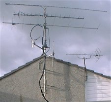
Gable antennas
The first thing I did was to completely strip the antennas off the mast that is bolted to the gable on the South end of the house. The 23cm 35 ele Tonna was finally replaced by an extended ‘M-Squared’ 35 ele (now 43 ele). The 13cm 25 ele came down on account that the accompanying transverter was just NOT working, and the old 18 ele parabeam shifted up in its place, just leaving room, albeit not optimum spacing, for my now un-bent 8 ele Eagle for 2m at the bottom. Also present on this little mast are a UHF dipole for 70cm and a VHF dipole. As can be seen from the photograph below, there have been a few additions to the shack. I was fortunate to get a good deal on a second-hand ICOM 706MK2 which prompted me to resurrect my 6m 3-ele beam.
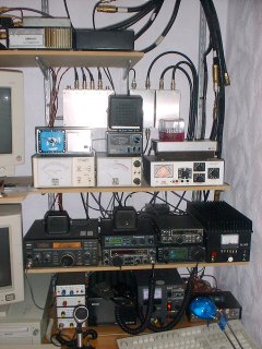
Shack changes Sept. 2003
The 706 uses ALC to control the output power in such a way that even when low power is selected it will always initially output several milliseconds worth of full power. Because of this, I still use the IC260 to drive my 2m amplifier. It would have been convenient to use the 706 but I felt that with the MK2 capable of delivering 20W on 2m, it was simply not worth the risk of blowing the PA in the amplifier. Consequentially, the 2m output on the 706 is attached to the dipole on the gable end. The Trio TR-8400, on top of it is connected to the UHF dipole. Ideally this ‘wee’ radio would be used for connecting to the DX-Cluster, but since there ain’t such a thing here in central Scotland, it is used in conjunction with my VX-1 when doing antenna work. It is good to be able to speak to someone in the shack when making fine adjustments to antennas.
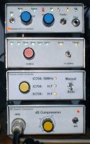
Three little boxes became four! I have always loathed having to climb onto the desk in order to lean over the back of the radios in order to change antennas. Now in possession of two competent H.F boxes, and with the 706 doing 6m too, it was time for some ingenuity!
The box second from the bottom (left) controls yet another remote switch-box on the wall above and behind the radios. Although this time it is a bit more than just a routing box. The 725 and 706 connect in at the bottom. On top there are two outputs; one for 6m the other for H.F. Either the 706 can be selected and switched between H.F and 6m or the 725 can be chosen, in which case, H.F is the default. The inputs to the box are also R.F sensing so that when transmitting, the other input is automatically grounded, thus protecting the other transceiver. There is also a manual setting which automatically grounds the ‘unused’ input when the other one is selected. This remote routing box can be seen in the photograph above, just behind and to the right of the Revex power meter with the ‘speaker’ on top.
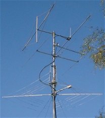
13cm 25 ele on main mast
Finally, I have never been one to run from a challenge and after consigning the 13cm transverter to the ‘junk box’, I repented of my brash decision. I systematically tested all the active devices and came to the conclusion that the mixer was faulty and decided to replace it with a Mini-Circuits ADE-3G surface mount device. Fortunately only minor track changes were necessary, and the transverter burst into life and now delivers a good clean 1 Watt of power. With 13cm now a viable band, I needed a perch for the antenna. There were still two spare runs of 4-50 coax on the main mast and one of these was a single uninterrupted run of FSJ4-50B, all the way past the rotator and which had once fed my UHF colinear. Thus, the end-mounted 25 ele Tonna is now mounted on the main mast, half way between the 6m beam and the Mini-Quad. Now if I could just find someone to work on 13cm! . . . Hmmm?
13cm on left, 23cm on right
I have long since adopted the principle that if something is working, it is best left alone, and if to be left alone, it should first be built to a standard such that it should also look good.
Earlier in 2003, I made the decision that I would at some point, re-box my 23cm transverter. Now in November, and having just resurrected my 13cm kit, I felt that it was fitting to honour my ‘re-born’ 13cm transverter with a similarly attractive case.
Since transverters tend to be by nature an extension of the ‘prime mover’, in my case my old but trusty IC260, the transverter itself requires very little in the way of front panel annotation. Thus, I have gone for a minimalist approach, painting the front panels matt black with nothing more than an identifying legend and two miniature LEDs: A green one to indicate that the 13.8V line is live and a red one to indicate that the transverter is in transmit mode.
Internal view of 23cm transverter
The 23cm transverter is based on DB6NT’s MK1 version as published in DUBUS 4/92. The only difference being that I employed a Mini-Circuits SAM-5 mixer of which I have many, instead of the Synergy SMD-C3 specified in the DUBUS article. As can be seen in the photograph, the basic transverter is tiny, measuring only 75mm by 55mm. On it’s own, the transverter delivers around 1.2W with very respectable receive performance. The overall performance is augmented by the inclusion of a GaAsFET pre-amp utilising an Avantek ATF-10135 (bottom right) and a 20W PA utilising a Mitsubishi M57762 power module (far left).
Internal view of 13cm transverter
The 13cm transverter is a real mixture of technologies and has evolved as a result of availability, rather than necessity. The basic transverter (top) is based on DB6NT’s MK1 version as published in DUBUS 3/93. The only difference being that I employed a Mini-Circuits ADE-3G mixer, instead of the Synergy SMD-C3 specified in the DUBUS article. The PA (bottom) is from my original 13cm kit dating back to 1986 and uses bipolar devices in the form of a BFQ34 driving a BFQ68 delivering about 3W. The pre-amp (left) likewise, was also part of my original 13cm kit, but has been subsequently modified to be a no-tune affair employing an MGF4919 HEMT.