Another R1155 Restored
6 minute read
June 2012
R.1155A, Serial Number unknown
This particular specimen came in with an RA17 for refurbishment. It had been bought as part of a ‘Silent Key’ sale. It came with a power supply and had a 1960s vintage transistor radio stuffed inside as an audio stage! The new owner hadn’t yet powered it up, which was probably wise since the PSU looked lethal and more than a few of the iconic tall tubular capacitors had leaked all over the under-chassis wiring. For some reason, the front plate supporting the Perspex blister had been painted light grey. The front panel-mounted trimmer capacitor (C57, part of the DF circuit) had been removed, the access hole enlarged and a quarter-inch jack socket fitted. The mixer-oscillator valve was not the usual VR99, but a 6K8G. The latter is described as a ‘sensible’ replacement for the VR99. The serial number plate was also missing, and since this was not ‘inked’ onto the chassis as in later specimens, I have no idea what the serial number is. However the type 13 tuning drive complete with vernier dates it around early 1942 at the latest. With the exception of C57, the DF circuitry was complete. All the valve heaters checked out good, but it remained to be seen just how ‘good’ the valves were. I am very grateful to two members of the Royal Signals/19-Set Yahoo group for providing the missing C57 and a replica serial number plate. I saw no reason why this receiver should not be brought back to life. And it is perhaps fitting that such a receiver be restored in time for the Bomber Command memorial opening. It is probably safe to say that around 8,000 of those who were lost in action were Wireless Operators.
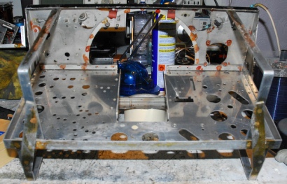
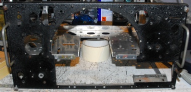
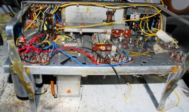
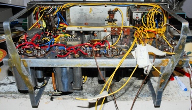
Chassis stripped and cleaned of all that hideous shellac varnish that appeared to have been daubed everywhere.
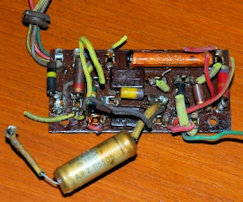
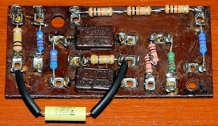
Before and after shots of the bias tag-board. Note the three 10K resistors making up 30K and the two 1K resistors making up 2K. Since this board proves the various bias voltages around the receiver, it is not wise to use nearest preferred values.
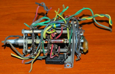
This is the Master Switch as removed from the set. Generally the state of the wiring was good. The rubber insulation had not perished and become brittle. However, elsewhere, where tinned copper had been used and had been sleeved with yellow rubber, this HAD morphed into what can only be described as dry macaroni! Also seen for the first time were OV and TGC inspection stamps. The chassis bore an embossed MWC stamp.
OV was Osram Valves and TGC was The Gramaphone Company. Osram was actually part of the Marconi group. The TGC stamps imply that the assembly of this R1155 was very likely carried out by EMI who had been formed as a result of the merging of TGC. and ‘Columbia Graphaphone Co.’ in 1931.
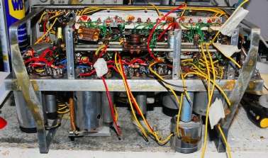
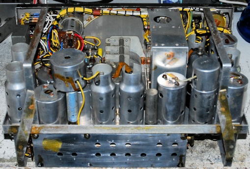
Clock-wise from right … a montage of views of the R1155 during stages of re-build, with the frightening coil-box being amongst the final part to be fitted. The ‘Magic-Eye’ is actually the final part to be wired up.
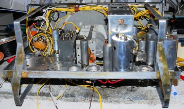
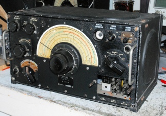
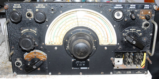
This is the finished article; fully working and laced up. I wish I could say that it worked first time, but it didn’t. For various reasons, work had been interrupted once or twice and as a result, a couple of minor wiring errors had crept in. Then during some initial HT voltage measurements it was noted that the bias on the Mixer-Oscillator was incorrect. This was the valve that had been replaced with a 6K8G. I removed it and fitted an ex-equipment VR99 and the discrepancy was resolved. Alignment was more or less straight-forward. However there were a couple of issues relating to the DF circuitry. The Meter Amplitude control worked in reverse and the Meter balance control was unable to null out the imbalance. The latter was identified as a valve issue by swapping V1 and V2. In doing so the imbalance flipped over the other way. I chose V1 and replaced it with an new VR99A; The Meter Balance control was then able to null out the imbalance. The problem with the Meter Amplitude control operating in reverse was a curious one since the wiring appeared to be fine. However there were two types of potentiometer that could be fitted. I replaced the ‘standard’ pot with one with a 6K5 resistor on a small tag as per my AD8882B. This fixed the problem. So I think there might be a problem with the way I interpreted Peter Holtham’s wiring diagram for standard 3-terminal pots. Murphy’s Law struck soon after lacing up the wiring. The set failed on Range 3. Or rather the Local Oscillator became slow to start on that range. This turned out to be an issue with the VR99 that I had fitted. Replacing it only temporarily resolved the problem because I then noticed that L4 in the first stage was no longer tuning. This did not bode well because to remove L4, I was going to have to de-solder connections under the coil-box. The R1155 was never designed to be maintained! In 1943, the life expectancy of a bomber was only 3 weeks! I managed to extract L4 and found that the iron slug had become detached from the Bakelite adjustment screw. I replaced the entire L4 assembly with one from my box of spares. I could have been forgiven for thinking that that would be the end of my problems. But no! The set then stopped working on range 1, then it finally failed on all 5 ranges. This turned out to be a Local Oscillator injection issue and was actually caused by failure of the VR99 mixer-oscillator … again! So I replaced it with a NOS VR99 and it has worked fine ever since.
The thing you have to remember with the R1155 is that it was never Intended as a high-spec communications receiver. The presence of the BFO served only to render CW signals readable. There are also more controls on the front panel related to Direction Finding than to actual reception. As a general receiver of AM broadcast stations it performs very well and this one even compared rather favourably with my RA1772 at 17.5MHz. I think it is worth the effort restoring these classic receivers just to get a feel for what it was like for the young men who operated them and the companion T1154 transmitter during WW2 and as a testimony to them.