The Racal RA117
18 minute read
September 2012 ... I finally have an RA117!
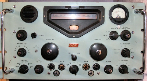
This had sat in my radio room awaiting refurbishment for several months … other more pressing projects having precedence. When I picked it up I was forewarned that it was faulty. Fortunately it was complete, so getting it working was as far as I was concerned, just a matter of carrying out a full refurbishment. The main tuning bezel is attached by way of three screws and there is a small scuff in the bottom left corner of the front panel where the primer coat is visible. Behind the front panel, the chassis bore the usual signs of ageing and the warning label shielding the RX-mute terminals was missing … but apart from that, the set was in good condition. … So, on with the job!
Curious as to exactly what the fault was, I ‘fired’ it up as soon as I got it home. Just to be safe, I ran the volts up slowly via a variac. I didn’t want any ‘loud’ surprises! It actually worked! Granted, it was very deaf though. But it was indeed a good start. When it came time to start the ‘refurb’ proper, I removed all the under-chassis covers and looked over each compartment with a ‘close eye’. The first thing that caught my eye was the tiny EA76 wire-ended AVC Clamp Diode where two of the wires had snapped off right at the glass envelope. Normally this would automatically be replaced with a silicon diode such as an 1N916. However, since I had a spare unused EA76, I decided to fit that instead. It didn’t fix the fault. I didn’t expect it to either, but it just seemed right to fit an original thermionic diode. … Time to focus on the job and that meant turning my attention to the PSU and audio amplifier compartment.
Curious as to exactly what the fault was, I ‘fired’ it up as soon as I got it home. Just to be safe, I ran the volts up slowly via a variac. I didn’t want any ‘loud’ surprises! It actually worked! Granted, it was very deaf though. But it was indeed a good start. When it came time to start the ‘refurb’ proper, I removed all the under-chassis covers and looked over each compartment with a ‘close eye’. The first thing that caught my eye was the tiny EA76 wire-ended AVC Clamp Diode where two of the wires had snapped off right at the glass envelope. Normally this would automatically be replaced with a silicon diode such as an 1N916. However, since I had a spare unused EA76, I decided to fit that instead. It didn’t fix the fault. I didn’t expect it to either, but it just seemed right to fit an original thermionic diode. … Time to focus on the job and that meant turning my attention to the PSU and audio amplifier compartment.
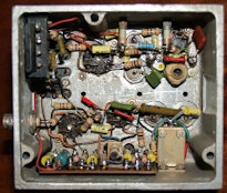
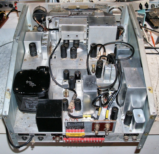
In the PSU area, the RA117 differs from the RA17 and 17L in that the ubiquitous GZ34 rectifier has been replaced with a semiconductor bridge, the mains cord is hard-wired in and there is no mains voltage selector.
The two EF91 audio pentodes have been replaced with a 12AT7 double-triode and a 6AQ5 pentode. The latter provides a more comfortable 1W output compared to the feeble 50mW of the UK version of the RA17/17L. It can be argued that the RA117 is a derivitive of the RA17C12 which was manufactured for the North American market and sported a genuine S-meter and ‘beefier’ audio stage.
It should also be noted that the RA117 (followed by the 117A and 117E) was NOT a replacement to the RA17L. It came about in response to a specific requirement and was manufactured alongside the RA17L.
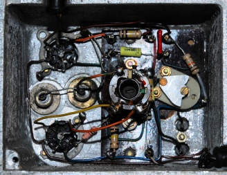
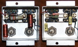
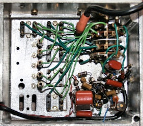
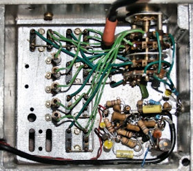
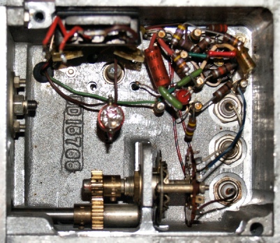
As can be seen, some of the PSU/Audio components had been previously replaced. However the only one which I retained was the 0.47uF capacitor across the negative bias line. In the RA117, the 165R resistor is replaced with a 120R one.
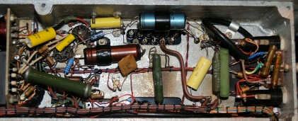
PSU/Audio compartment before and after
Spot the difference!
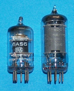
I decided at this point, to concentrate on the under-chassis compartments. In the past, I have left them to last and proceeded straight to the front-end. As previously stated, the RA117 was initially manufactured in response to a US DoD requirement … and like the RA17C12, the RA117 was designed around (or incorporated) North American valves (called tubes!). It looks like the RA117 design benefited from lessons learned from the RA17C12 in that many of the valves are different. For instance, in the UK version of the RA17L, VFO1 is an EF91. In the RA17C12 it is a 6AU6 or EF94. Now in the RA117, where a 6AU6 was fitted, it is now a 6BA6 or EF93. In almost all cases, there is a direct UK replacement valve for the North American ‘tube’ … that is with the exception of the 6AS6. This is the Harmonic Mixer immediately following the Harmonic Generator. RA17s and RA17Ls manufactured for the UK employed a 6F33 (or CV329 or CV2209). However, there is a subtle difference. Whereas the 6AS6 is electronically identical to the 6F33, it is mechanically incompatible since g2 and g3 are transposed. With this in mind, I decided to lift the can off V4, the 6AS6. Imagine then my surprise when I found not a 6AS6, or a 6F33, as one might expect, but the valve on the right. The lettering is a tad worn, but I’d say it’s a CV2009 (or EF93, CV454, 6BA6W). What gets me is how on earth this ‘rogue’ valve was actually surviving since with respect to the 6AS6, the cathode and g3 are actually transposed. I promptly replaced it with a ‘genuine’ Russian’ 6AS6 and the RA117 was instantly transformed!
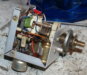
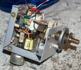
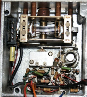
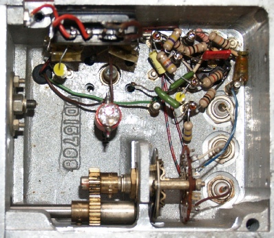
RA17L 1MHz Oscillator on the left with RA117 circuit on the right … they are quite different. The 17L uses EF91s while the 117 uses 6AK5s.
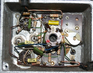

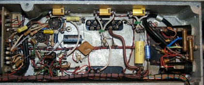
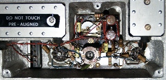
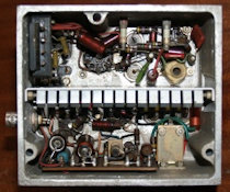
Harmonic Mixer etc. before
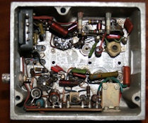
Harmonic Mixer etc. after
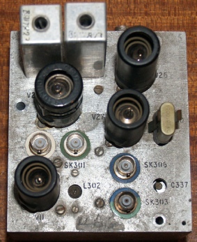
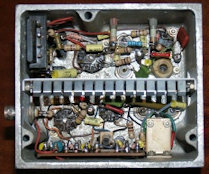
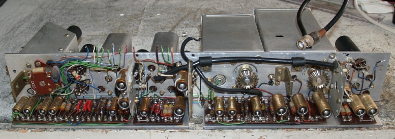
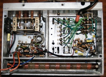
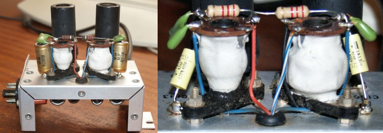
The second mixer brings together the outputs of the 40MHz and 37.5MHz band-pass filters. The layout is very similar to that in the RA17L etc. However, note the 4-pin power connector on the far left … this carries the HT and heater supplies up to the 1.7MHz/third-IF module. When aligning the second mixer, it is important that the trimmer capacitor is 50% meshed as a starting point. Then simply adjust the inductor for maximum deflection on the front panel meter. Then go back to the capacitor and move it either clock-wise or anti-clock-wise slightly (a few degrees). Then readjust the inductor core. The idea is to find a setting on the capacitor that corresponds to a maximum reading when the inductor is adjusted.
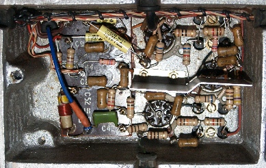
Second mixer before
Second mixer after
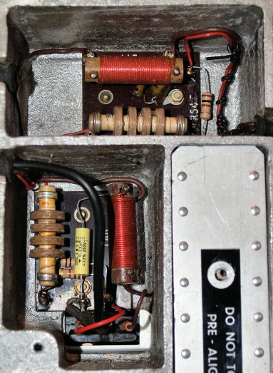
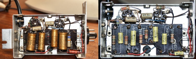
These are the HT and heater filters for the 1MHz Osc. and harmonic amplifiers (top) and the first VFO/Front-End unit. The latter differs from that in the RA17L in that the 220nF capacitor is a new addition and the 68K resistor in the AVC line has been replaced with a 100K resistor and is now located elsewhere.
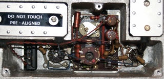
The 1.7MHz module is easy to remove from the chassis, but not so easy to refurbish, owing to the cramped nature of it’s design. This is largely due to necessity. Although it is generally referred to as the 1.7MHz module (because it contains the 1.7MHz crystal oscillator), it also contains the second VFO amplifier as well as the third and fourth mixers! I was fully expecting to find a few horrors inside due to heat build-up in such a confined space. However, apart from the odd resistor going high, the contents of the box were in reasonable condition. Traps L300 and L301 are in a small sub-chassis adjacent to the 1.7MHz module and can be dealt with at the same time.
Alternatively you might want to address this while working on the second mixer since the sub-chassis is held down by the same screws which retain the second mixer tag-board. L300 and L301 are necessary for removing unwanted signal content from the output of the second mixer. L300/C300 removes the 37.5MHz content. L301/C301 removes any 6MHz content. This is explained in Section 2, Ch1 of the RA117 manual.
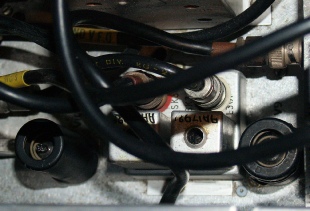
L300/301 sub assy.
Anti-clock-wise from top left … It is first necessary to remove the divider screen. The small tag-board at the bottom of the picture is reminiscent in a small way of the board found in the second VFO in the RA17 and RA17L. Care should be exercised in relation to the fine wires associated with the two variable inductors. It might be seen as a good idea to test the oscillator prior to refitting the screen. Note also that L330 which is on the little tag-board cannot be accessed once the module is refitted to the chassis.
L302 (in conjunction with C308A) forms a 1.6MHz rejection filter. This is explained in para. 26 of the alignment procedure in the RA117 manual.
The 0.1uF capacitor just above the screen in the final photograph is across the heater line and is a new addition.
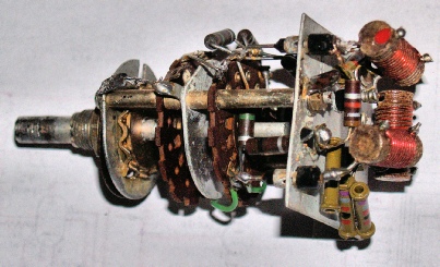
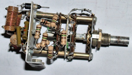
In the RA117, the 100KHz ‘strip’ is the fourth IF; the other three being 40MHz, 2-3MHz and 1.6MHz … otherwise it is identical to that found in the RA17L.
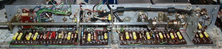
Here it is fully refurbished with the bandwidth switch shaft re-fitted. Note that the shaft has been rubbed down with a fine abrasive. This was necessary since I had a terrible time getting the gears off. The Allen grub-screws were, as usual, bonded in place with locking compound. However the biggest problem was with the retaining ferule between the rear bracket and the rear gear. In the end I simply drilled through the aluminium ferule with a bit the same diameter as the ferule is wide. This enabled me to ‘split’ it so that it would slide off the shaft. ALL the grub-screws had been screwed in so tightly that their ends had actually formed ‘pits’ in the shaft. This made it difficult to slide the gears off despite the screws being retracted. A hammer and centre punch was necessary to effectively knock the shaft through the gears! … hence why the shaft had to be ‘polished’.
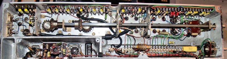
This is the fourth IF strip reinstalled in the chassis. Note the extra RF-Choke at the bottom of the picture. This is in the HT line to the 1.7MHz module. You can also see, to the left of the choke, a 100K resistor on a ceramic stand-off. This is the resistor, which in the RA17L is usually located next to the HT and heater decoupling chokes. Finally … having destroyed the aluminium ferule, I replaced it with a piece of brass tubing which just happened to be the perfect size … so no need for grub-screws!
The BFO: What was an EF91 in the RA17 and 17L and a 6AU6 in the RA17C12 is now a 6AK5W in the RA117 … the basic circuit is essentially the same but with the addition of one resistor (27K) in series with g2, and it’s associated decoupling capacitor.
The next stage is to remove VFO1 and VFO2 from the chassis. At this point it is always a good idea to remove and refurbish the RF attenuator and the meter rectifier tag-board. The latter cannot be removed when VFO1 is in place and access to the four resistors and the rectifier is extremely difficult when it is in place.
Note the 1K8 resistor in the photograph on the left. This is across the input of the Low-Pass filter. I haven’t been able to find any record of this being fitted as a sanctioned mod, so I removed it.
Working on wafer switches is always tricky. The greatest risk is that the terminals get broken off when removing components. I don’t think I have even encountered a faulty resistor in one of these attenuators, however I have found one or two solder joints which had failed to the extent that the attenuation was excessive. Replacing the resistors, even though they are in spec is probably wise just the same.
The ‘front-end’ of the RA117 differs from that in the RA17L in that there is no 0.5-1MHz pre-selector. Instead there are now two broadband positions; one of which like in the RA17L, the input is terminated in 75R and the other where the input is terminated in 2K2. As can be seen from the photograph on the left; a previous owner had replaced the old tubular decoupling capacitors. I replaced these with more modern ones.

As previously mentioned, the first VFO is now an EF93. R39 (V5, g2) is increased from 1K to 22K and R41 is now 10K as opposed to 47K. The first mixer is still the trusty E180F (or CV3998).
Again, some of the old tubular capacitors had been replaced … and again I replaced them per-se, in keeping with the rest of the capacitors in the radio.
Finally, VFO1 in the RA117 has an extra bracket attached to the lower front edge. This has two tapped holes (or hank-bushes) for screws which come up from under the chassis. These were missing at the time but I have a large box of miscellaneous screws and it was just a matter of rummaging through it until I found two appropriate UNF threaded screws. I can’t be certain, but this additional bracket may be a way of improving the ‘grounding’ and thus improve the signal-to-noise ratio. It is a good idea to test the unit at this point since access is non-existent once the radio if fully re-assembled. At this point I noticed that something wasn’t quite right with the tuning of the pre-selector. This turned out be the result of someone fitting the ‘stop mechanism plate’ on the variable capacitor upside down and was restricting the HF end of the AE tune control.
VFO2 is precicely that. Unlike in the RA17 and 17L where the box also contained the third mixer, in the RA117 it is simply just the second VFO. It is however a completely different animal. Without the need for the tunable (2-3MHz) band-pass filter, the unit is considerably smaller, and lighter. In the RA17 and 17L, the second VFO is an EF91 and tunes from 2.1MHz to 3.1MHz. In the RA117, the second VFO is one half of a 12AT7 double triode and tunes from 3.6MHz to 4.6MHz.
Provision is also made for selecting an external local oscillator.
This is a relatively easy unit to work on. Even removing it from the main chassis is easy. On the RA17 and 17L, in order to remove the unit it is first necessary to remove the lid of the module simply to gain access to one of the two long screws which secure it to the chassis (there is a third, short screw also). However, Racal obviously realised that this was poor design and replaced this ‘hidden’ screw with one which comes up from underneath, with the tapped thread being in the VFO casting as opposed to the main chassis.
The additional capacitor on the left in the lower photograph is a 47nF capacitor across the heater supply. This features in later models of the type.
Again, it is wise to test this unit prior to re-installing.
No surprises with the Calibrator … the design of this little enigmatic box has remained more or less unchanged since it’s inception.
It is also very easy to work on. It is often much maligned though as a ‘pig’ of a circuit to get working. I’m no magician, but I have re-built at least eight calibrators to date and never once have I encountered a problem.
If you don't have access to an accurate signal generator, here is a possible alternative adjustment procedure to the one in the manual.
Obviously you need a working receiver. With the System switch set to ‘Cal’ tune the KHz dial to a multiple of 100. 500 is a good starting point. Now adjust L69/70 (the one furthest from VFO2) for an increase in noise or even a tone! If L75 is not properly set you are more likely to get noise rather than tone initially. Now adjust L75. Generally you will hear a further increase in noise and then possibly a spontaneous tone. It may be necessary to adjust the KHz setting too. If you don’t get a tone it is likely that you have tuned one of the cores to a ‘false’ response. In which case you just need to find the correct one by re-tuning either of the two cores. Once you have a tone, verify that it is present every 100KHz from 0 to 1000. If not, it is simply a matter of carefully tweaking either of the two cores again (most likely L75) and verifying the response over the range. It isn’t a ‘black art’. I think it is just something that you get a feel for.
 Job done!
As can be see, the RA117 cleaned up rather nicely. Performance is also quite astonishing. As usual, SSB reception is more than acceptable provided you don’t overload the detector. For this reason it is sometimes necessary to add in attenuation at the front end and/or back off the IF gain. According to the manual, the signal-to-noise figure at 1.5MHz should be at least 18dB. I have checked and double checked my test setup and repeatedly get a figure of close to 27dB. The same is also so for an RA17L that I have just refurbished. I can only surmise this improvement is due to the use of modern, higher quality resistors.
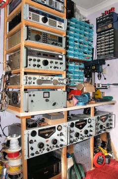
So this completes my Racal collection for the moment:
Below the bench, left to right … RA17 N664, RA17L N8854 and RA117 N0489
Above the bench and going up … MA197 Pre-Selector, RA1217, RA1772, RA1792, RA3701
I also have an RA218 ISB adapter which is missing the 18KHz crystal. These obscure LF dual crystal devices are virtually impossible to come by, so I have designed and built a modern solid-state circuit which derives 18KHz from a 12.6MHz monolithic oscillator. I just have to fit it into the RA218 in such a way that it doesn’t detract from the original build. Once that is done, there is just enough room on top of the big Racals under the bench.