The MA79 Transmitter Drive Unit
37 minute read
This post is part of the series 'MA79 Drive Units':
Since January 2009, I have stripped and refurbished over 50 Racal RA17s, 17Ls etc. and RA117s. I’ve given the same treatment to several RA137s and 37s and at least one of every Racal sideband adapter … I’ve even got an early MA259 Frequency Standard bearing serial number N1 and an SA97 wobbulator for setting up the infamous 40MHz bandpass filter in the ‘Wadley Loop’.
But until about a year ago, I’d never had my hands on an MA79 Transmitter Drive Unit. It therefore goes without saying then that the last 12 months have been both interesting and a very steep learning curve. Whereas there are thousands of working RA17s out there … how many people do you know who have a working MA79?
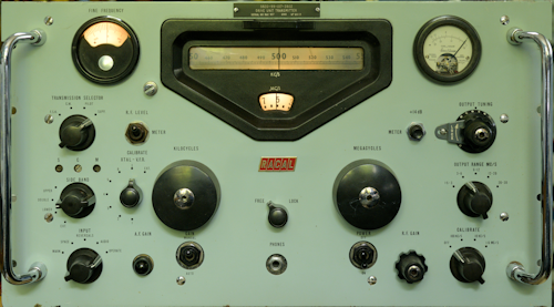
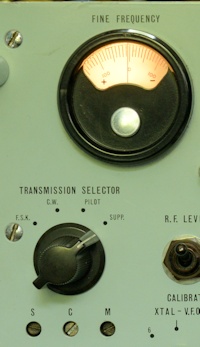
At first glance, the MA79 is often mistaken for an RA17. The front panel layout is initially familiar, until you look more closely. Like the RA17 there is no precise description of what it is on the front panel, although the legends associated with some of the controls might give the game away. The inclusion of a headphone jack, on the other hand, might be seen as a tad confusing.
I have just spent the best part of a year, maybe longer, getting to grips with an MA79H. A very good friend who had no less than four untested MA79s asked if I was interested in taking them on as a project. Not being one for turning down a challenge, I said yes, and arranged to pick them up.
An initial survey suggested that I was looking at a couple of MA79Hs, an MA79G (or maybe a D?) and an MA79A-1. Closer examination yielded some curiosities ...
MA79 Ser. 753: MA284 and LA255 fitted but no PL20 (1.4MHz o/p) ... so likely to be an MA79A-1 with an MA284 fitted by mistake.
MA79 Ser. 597: Lavoie crystal oven fitted. No PL15 on rear panel! Also, No L7 audio transformer ... so possibly an MA79D, which had no provision for modulation.
MA79H Ser. 937: No MA284 but did have a dual crystal oven with two 1MHz crystals fitted in its place!!
MA79A-1 Ser. 139: MA284 and LA255 both fitted. MA284 clearly fitted by mistake as the MA79A had an internal frequency standard.
Ideally my friend was looking for two working examples. The MA79A-1 was missing more than a few front-panel components and the input side of the PSU was completely smashed, so it was designated as a spare-parts donor. Serial number 597 was also put aside since it lacked PL15 and the input audio transformer. This left me with serial number 937 which was labelled as an MA79H, and MA79 serial number 753. The MA79H was missing an MA284, but I would use the one out of the scrapped MA79A-1. MA79 Ser. 753 is a curious piece. The lack of PL20 indicates that it has no provision for external modulation (It does have the balanced audio input transformer, L7). So that makes it compliant with an MA79A. Fitting an LA255 is not a simple plug-in job, so it is likely that it was officially converted to an MA79A-1 at a later date. It does have the necessary 'free' D-Type connector and fittings for accepting an MA284. So I will probably go ahead and configure it as an MA79H
Unlike the RA17 series of receivers, and I will include the RA117s here too, where good quality manuals, user and service, are freely available, information on the MA79 is a different matter altogether. I am told that Racal never provided any of the end-users with anything remotely like a Service Manual. With that in mind, you might think that there would be plenty of User Manuals out there, but that is not the case. To date, I have come across only three PDF copies of a User/Technical Manual, none of which are complete … all are missing pages … different pages … and the two largest schematics are literally unreadable to be of any use. One of the PDFs has been produced from a non-loose-leaf copy where the text down the left side of many of the pages is unreadable. Here someone has then written the missing words into the margin, using either a blunt pencil, a child’s crayon or a knackered felt-tipped pen! There is even an official stamp on one of the pages stating that that particular copy is the best quality that is available
Given the complexity of the MA79, I can actually see why Racal did not release the Service Manual to the end-users, but why the lack of good quality User Manuals? We will probably never find out.
Note: As with all Racal equipment of the 50s and early 60s, frequency is 'measured' in Cycles per Second as opposed to Hertz. So, before we go on; Where reference is specifically made to the front panel, I will likely use Kc/s or Mc/s, but where I am describing the circuitry, I will probably revert to KHz or MHz.
So now I had the makings of a refurbishment project. At some point I was going to need to power them up. Somebody once said to me “If you’re going to get an MA79, make sure it’s a ‘G’, as the ‘H’ requires an MA350B Decade Frequency Generator in order run”. It is true that the MA79H does require an MA350B to provide 1MHz and 200KHz signals, but initially I got by using my Adret 740A to provide the 1MHz and my HP3325A providing the 200KHz. Although the MA350B is described as a Decade Frequency Generator, specifically designed to replace the Kilocycles VFO, that feature is not mandatory.
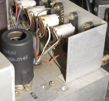
In two of the MA79s that I had chosen for this project, something had leaked a horrible brown sticky substance down the inside of the left side-plate (see image on left). This turned out to be ‘potting goo’ from the AF Input transformer. I can only think that this occurred as a result of the units being stored in a very warm environment. The only way to clean up the mess was to completely remove the metalwork that makes up the left side plate and scrape the 'goo' off with a sharp wood-chisel then use white-spirit to wipe the metalwork clean.
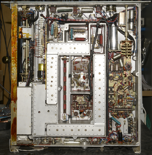
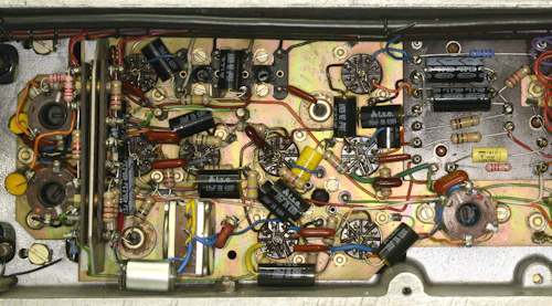
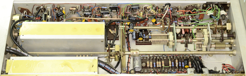
As can be seen from the photograph on the left, much of the underside of the MA79 looks familiar, particularly the compartments that are normally covered by screw-on lids. Indeed, these compartments are more or less identical to those found in any RA17. Even the layout in the PSU area initially resembles that of an RA117, but here, instead of the audio output stages we have the MA79's calibrator sub-assembly ... more on this later.
The MA79 resembles the RA17 in more than looks. It utilises the same ‘Wadley Loop’ drift cancelling technology which right away, makes it that bit more complicated than other transmitter drive units of the day. To be honest though, the MA79 actually has more in common with the RA117, utilising the same frequency conversions, albeit in reverse.
If you think the RA17 looks complicated, take a look at the coax cabling inside any MA79, above the chassis, then count the valves. The basic MA79G embodies no less than 33 valves. The MA79H has 35 since it contains an MA284 Mixer/Amplifier (more on that later). And if you have the LA255 Tone to DC Converter, where a ‘look-up’ of the Nato Stock Number, 5820-99-580-1976, identifies it as ‘KEYER, TONE’, add another two! That’s a possible 37 valves in total. Curiously, the LA255 on MA79 Ser. 753 had been miss-identified as a ‘TONE to DR CONVERTER’; a 'feature' which didn't help trying to figure out what it did.
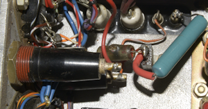
I make a point of never switching something on unless I am 100% confident that it isn’t going to go bang. A quick peak inside one of the MA79s revealed a ruptured 10nF capacitor (see left) which appeared to be across the primary winding of the mains transformer. I figured it was probably a good idea then to fully refurbish everything in the power supply. But there was a problem. What actually constitutes the PSU in the MA79? The User Manual has a schematic (Fig. 4), entitled Ancilliary Circuits. This is a fairly straight-forward schematic which also identifies three different HT and Heater distribution points, as well as the -25V rail, the main 250V HT rail and a +200V rail.
The downside of this is that as with all the schematics, this one has been reduced and each of the distribution points are given a lower-case letter which is difficult to identify. The two main schematics have both been reduced even further to the extent that considerable detective work … you might call it reverse engineering, is required to work out which distribution network serves which part of the MA79. Unlike the RA17 etc. the components which make up the PSU in the MA79 are literally scattered throughout its labyrinthian chassis. I didn’t stop with the PSU, choosing to err on the side of caution, I ended up giving the MA79H the same refurbishing treatment that I give RA17s etc. I figured that if I was going to have to ‘feel’ my way around the unit, it would probably make my life easier if all the Rs and Cs were the correct value … that’s the theory.
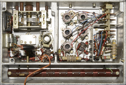
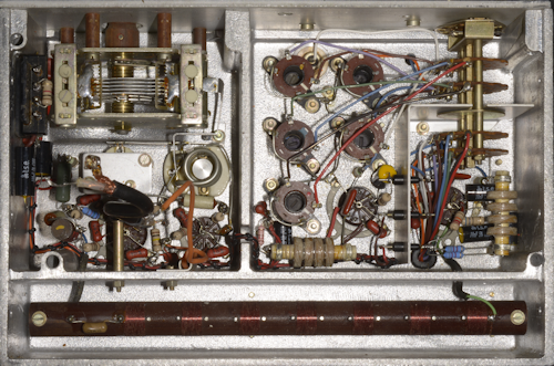
The photograph on the right shows three familiar HT and Heater distribution boards after refurbishment. To the right of these are four capacitors and a wirewound resistor which also form part of the 'distributed' PSU.
With the components in the PSU, and the calibrators (simply because they shared a compartment) replaced with modern types, I slowly powered it up using my big 8A variac. The two 6V lamps lit up and nothing went bang! So I was now ready to check out the MA79 ... But, where to start? A look at the block diagram was initially not very helpful. Like the main schematics, it too has been greatly reduced and badly copied. I decided to look for things that were familiar … like the Wadley Loop … and what exactly is the purpose of the MA284? It was then that I realised that because of the inclusion of the MA284, the MA79H actually has not one but two Wadley loops … How cool is that! Here's how that little extra box works, and why it is there ...
I actually re-drew the MA79H block diagram in such a way that the function of the MA284 was more apparent, and recognisable as forming part of a second 'Wadley Loop'. Without going into too much detail at this point, we need to understand that the basic MA97 relies on three crystal oscillators, running at 1MHz, 5MHz and 5.1MHz. The latter two are doubled to provide base frequencies of 10MHz and 10.2MHz. The 5MHz and 5.1MHz crystals share a common thermostatically-controlled oven which is situated in the Modulator assembly. However, with the use of multiple crystal oscillators comes an inherent risk of reduction in accuracy. A need arose where greater frequency accuracy and stability was required, which is why the MA79H was intended to be used in conjunction with the MA350B Decade Frequency Generator, which replaced the 2nd or KC/S VFO, and the 1MHz crystal oscillator. It also provides a 200KHz signal, the reason for which will become clear. All three of these signals are derived from the MA350B's internal frequency reference. For even greater accuracy and stability, that too could be replaced by the output from an MA259 Frequency standard.
Click here to view the MA79H block diagram.
With the MA284 installed, the 5.0MHz oscillator/doubler is disabled. The output of the 5.1MHz crystal oscillator/doubler is fed to Mixer 5 and the mixer in the MA284 where it is mixed with the 200KHz signal from the MA350B to produce 10MHz. In Mixer 5, the 10.2MHz signal is mixed with 1.4MHz to produce 11.6MHz. The 10MHz signal from the MA284 and the 11.6MHz signal from Mixer 5 are mixed in Mixer 4 to produce a super-stable signal at 1.6MHz. Any inaccuracy and/or drift in the 5.1MHz crystal oscillator is completely eliminated in the same way that 1st VFO drift is eliminated in the RA17 etc, and the MC/S VFO in the MA79 for that matter. AND, since the 1.4MHz signal that the 10.2MHz signal is mixed with is ultimately derived from the 1MHz signal from the MA350B, the accuracy and stability of the MA79H, when used in conjunction with an MA350B, is defined by the 1MHz output from the MA350B alone ... absolute genius!
As mentioned previously, I set up two synthesised signal generators to provide the required 1MHz and 200KHz signals. My first task was to figure out a way to test the MA284 and to confirm that it was doing what it was supposed to do, i.e ensure that anything that was 'tweakable' was in the right position.
Now to see if it would generate any power. A quick referral to the very 'iffy' manual did mention linking pins 3 & 4 and 5 & 6 on PL15 and a couple of necessary front panel settings. This, I did, and things began to happen. I even had a signal at the output, albeit noisy and not in any way related to the frequency that the controls were set to. Then all of a sudden, I had a meaningful output that did relate to the controls and the RF Gain control and ALC even had an effect; my Adret 740A and HP 3325A were clearly doing their thing!
I needed to verify the tuning of the two inductors on the MA284. The tall one clearly had a top core and a bottom core, but the cores had slots rather than hexagonal holes which would have allowed a hex trim tool to reach down through the top core to get at the bottom one. It was a bit tricky lifting the top of the box whilst it was on the main chassis, but I was able to access both cores and connect my spectrum analyser via a suitable isolated probe (coax lead and 100nF capacitor) to TP2 on the MA284. This allowed me to adjust the signal level from the two signal generators for optimum, whilst adjusting L1 (for 10.0MHz) and L2 (a trap to block 10.2MHz) for the best 10.0MHz signal at TP2 whilst minimising the 10.2MHz content. I was able to keep the latter at least 20dB down on the 10MHz product, and that appears to be adequate. I haven't found any specific instruction on setting up the MA284.
The switch in the centre of the MA284 should be set to 'IN' when the TRANSMISSION SELECTOR on the MA97 front panel is set to anything other than F.S.K., when it should be set to 'OUT'. More on this later.
This enabled me to ‘skim’ through some of the features of the Drive Unit, verifying that it would deliver an accurate frequency at the required power over its specified frequency range. It did, up to a point but at times the output signal was unstable and noisy, and the level did vary to the point that it was below spec. at times. If I switched it off for any reason, it was then a struggle to get it working again. There had to be a reason. I did discover that the point on the Octal socket bringing the 1MHz into the MA79 had been taken to chassis via a 68-ohm resistor. The reason for this is that the 1MHz output from the MA350B is designed to drive into 70-ohms. Lifting one end of the 68-ohm resistor did improve the signal significantly.
The failure to ‘start’ problem turned out to be the 100KHz calibrator, of all things. Whereas an RA17 can happily run without a calibrator, the MA79 will simply not function without its calibrator. As said, the calibrator works at 100KHz, 10KHz and 1.6MHz. The 100KHz and 10KHz positions are obvious and are used to calibrate the film-scale. The 1.6MHz part of the calibrator is used to calibrate the Fine-Tune control and/or the Mark/Space offsets. In total, the Calibrator Assembly in the MA79 has no less than eight valves. The reason for this, and why there is a headphone socket on the front is because since the MA79 isn't a receiver, the resulting 'beat frequencies' need to be made audible, by way of a harmonic amplifier (V29), a mixer (V33) and Audio amplifier (V32). The eighth valve is the 100KHz multiplier (V31), providing the basis for the 1.4MHz IF for the Modulator and the 1.6MHz calibrator … a clever use of the existing 100KHz signal.
Right: The underside of the calibrator module. As in the RA17, the 100KHz signal is produced by 'regenerative dividing' from the base 1MHz signal. This is then used in the same manner to subsequently generate the 10KHz calibration signal. Some RA17s were manufactured with such a 4-valve calibrator giving both 100KHz and 10KHz calibration points.
A Regenerative Divider, or Miller Frequency Divider, mixes the input signal with feedback from a multiplier. It operates in a similar way to an injection locked oscillator. Theoretically, division by any integer value is possible. In the MA79 100KHz calibrator, the 1MHz signal is fed into the divider stage (V27) which is tuned to 100KHz. A sample of this output is fed to the multiplier stage (V28) which generates the 9th harmonic, 900KHz. This is then fed back to the divider stage where it is mixed with the 1MHz signal thus ensuring that the output of this stage is exactly one tenth of the 1MHz input.
Should the desired output frequency be 200KHz, the divider stage would be tuned to 200KHz and the multiplier stage tuned to 800KHz. In the case of the MA79, the 10KHz calibrator works in the same way, but in this case, the input is 100KHz, the divider is tuned to 10KHz and the multiplier stage is tuned to 90KHz.
To be honest, Racal's regenerative divider is perhaps the most maligned circuit when discussing RA17s etc. I know of several users who have had so much trouble with the circuit that they have simply removed it. I will confess that although I have never encountered a problem with the calibrator circuit that was not the result of a hard fault, I can testify that for some unknown reason, some calibrators result in a weak, insipid calibration tone whilst others produce a healthy tone. I will also testify that following the detailed initial alignment procedure in the RA17 manual, it is ALWAYS necessary to adjust the tuned circuits slightly off peak to ensure reliable starting ... and the same is true for the MA79. In fact, finding the core positions which resulted in reliable starting of the 100KHz divider required several trial and error iterations. Having achieved this, the MA79H was now producing a healthy and accurate signal across most of its range. So back to checking and verifying the various features ...
But first; a brief synopsis of these features ...
Considering that the MA79 dates from the early 1960s, what it achieves is really very impressive. It can generate AM (full or reduced carrier), Double Sideband (Suppressed or Reduced carrier), Single Sideband (L.S.B. or U.S.B.), CW and F.S.K. (Frequency Shift Keying). All this with a frequency accuracy and stability like the RA17 or better, thanks to the use of Trevor Wadley's ingenious drift-cancelling system. Despite the fact that the power output is only specified as 100mW, a well aligned MA79 is capable of delivering up to 700mW or more, but this is not advised as the life of the output stage will be compromised and the grounded-grid EL821 runs very hot under normal circumstances anyway.
Not all MA79s were made equal ...
Without describing all the variations; To give some examples; The MA79A had no provision for external modulation, i.e. it did not have a 1.4MHz output or a 1.4MHz input. The MA79D was CW only ... and presumably F.S.K. also, but I cannot confirm this.
Although the MA79H was now 'starting' reliably, and delivering what was potentially a good signal, I was still concerned that there was a discernible, albeit low-level amplitude modulation visible on the carrier wave. This was by chance traced to the Cathode Follower on the AF input to the Modulator, or rather the unused half of the 12AT7. Someone had cleverly used what was the unused half of V6 (12AT7) to construct an audio preamplifier and 'slotted' it in between the balanced input transformer and the cathode follower. It actually worked very well but because of its relatively high gain, it was introducing noise into the modulator circuit. I opted to 'take it out' and the noise on the signal disappeared.
So, after a couple of false starts, I was now ready to work my way through the MA79H. My plan with this one was to perform a full system refurbishment. For this reason, the two VFO modules would be removed first, just like working on an RA17. Even if not doing a full 'refurb' on the MA79, it is probably wise to consider removing the two VFO modules and replacing all the carbon resistors and paper capacitors anyway since these are the only components in the MA79 which are not readily accessible.
Left: If this were an RA17, it would be referred to as the 1st VFO. In the MA79, it is referred to as the Mc/s VFO. As you can see from the photograph, the inside looks very similar to that of a MK1 or MK2 RA17. The compartment on the right houses the two tuned amplifier stages. The Low Pass filter is identical to that in the RA17. The technical manual does give a fairly detailed description of the various parts of the MA79, and there is even a comprehensive guide to alignment. But where the manuals for the RA17, RA17L and RA117 all give comprehensive details on how to align the pre-selector, there is no such table of frequencies for aligning the tuned circuits either side of the EL821 in the MA79. It would have been be nice to have a starting point. Initially I treated it like an early RA17, which did work, up to a point, but I ended up with double humps in the tuning and at least one range where the maximum output dropped to as low as 50mW. In the end I found the best approach was to perform the alignment close to the 'top' of each range and then go backwards and forwards over the range to smooth out any extra responses. This also resulted in minimum output over the entire range never being less than 100mW.
The following may be used as a 'guide' for aligning the two sets of tuned circuits associated with V26 (E180F) and V31 (EL821).
Set the OUTPUT TUNING to 8, GAIN to MANUAL and R.F. GAIN fully clock-wise, then either inject a signal at TP3 (between V20 & V23) if testing the module alone, or set the MC/S and KC/S controls to the frequencies listed below and adjust each pair of Input/Output transformers in turn for maximum output at PL12, ensuring also that you do not have a 'double-hump' response.
Trimmer capacitor C168 (6pF) is in parallel with C166 (212pF), which is ganged with C214 (also 212pF). Without wanting to sound cynical, it will come as no surprise that the manual only mentions the existence of C168, but fails to explain its purpose. I can only suggest that it might be there to provide minor adjustment should it be necessary to replace V26, obviating the need to retune all 5 ranges (L39 thru' L44). Thus probably best to leave it set mid-travel.
Above: Before refitting the VFOs, like with the RA17 etc., one of the screws securing the 30MHz LP filter on the output of the harmonic generator is obscured by the MC/S VFO, so whilst the VFO is off the chassis, now is a good time to change the two resistors at one end of the filter.
In the 2nd or KC/S VFO, the VFO (V7, EF91) is based in part on the 2nd VFO in the RA17, however, the module also embodies a 6-channel crystal oscillator (V4, 6AS6). All the passive components are contained within a thermostatically-controlled oven.
As said, the actual VFO here is similar to that found in the RA17 and RA17L, although the enclosure bears an obvious resemblance to that found in the RA117, especially the switch mechanism which, in the case of the MA79, is an 8-way switch. This offers the user up to 6 possible crystal-controlled options, Internal VFO, or External (VFO, Synthesiser or Crystal). In this particular case, positions one and two are populated, with crystals for 4200KHz and 3750KHz which translate to x.400MHz and x.850MHz respectively. Unfortunately, I discovered that the heater element for the oven was open-circuit, and since it is bonded to the inner wall of the upper enclosure, it is far from easy to repair or replace. However, since I have two MA79s sitting here which are either beyond repair or of little use (as in the MA79D) I had access to two potential replacement VFOs. Although both turned out to have intact heaters, I ended up using the VFO out of the MA79D as the VFO in the MA79A-1 turned out to be physically damaged beyond economical repair.
Here's a thought ... I have heard it said that the MA79 is like an RA117, but in reverse. The two main VFOs operate over the same frequency ranges. I read somewhere that since both KHz VFOs tune between 3.6MHz and 4.6MHz, that it may be possible to slave the MA79 to an RA117. However, the KHz tuning in the MA79 is in the opposite direction: The numbers on the scale increase from left to right, as opposed to right to left on the RA117. This is because of the extra conversion stage which 'flips' the tuning. So, much as it sounds like a good idea, it isn't possible to slave an MA79 to an RA117.
With the two VFO modules refurbished and their functions verified and aligned, we move on to more familiar ground, and this is where we realise that the inner workings of the MA79 are not all based on the RA117. For instance, what is the 1MHz oscillator in the RA17 is exactly that in the MA79, when running an internal 1MHz source, otherwise the same circuit (V1) doubles as an amplifier when the 1MHz source is external. Likewise, the Harmonic Amplifier (V3) in the MA79 is almost identical to that in the RA17; the difference being, the cathode is taken to ground via 560 ohms. Also, the MA79 used two EF91s here where the RA117 uses a pair of 6AK5s ... but that's another day.
I have two MA284s in my possession right now. The 'prettier' of the two is in the MA79H. While going through my photographs of this project and looking at the 68-ohm resistor, which acts as a matching load for the 1MHz output from the MA350B. It struck me that whilst one end of the resistor was indeed connected to the point where the 1MHz signal is applied, the other end did not appear to be connected to ground, in the photograph. It was simply soldered to pin 2 on the Octal socket. A quick check with a multimeter confirmed that pin 2 was indeed connected to ground (chassis), implying an internal connection within the MA284. That explains the pink wire in an earlier photograph of the inside of the MA284. Thus when the 1MHz source is internal, the 68-ohm resistor is disconnected. Interestingly, the grubbier and older (Ser. No. 4) of the two MA284s doesn't have this internal wire to ground. Also, there is no link between pin 2 and ground in the adapter lead shown in Fig. 15 of the manual.
Important note: Connecting pin 2 to ground applies only to chassis configured for a Lavoie oven. If configured for a Knight oven, I would expect pin 6 to be connected to ground. See Figs. 3 or A-5, and Fig. A-2 (relates to MA284) in the documentation for more details. Note that these connections are missing from Fig. A-3.
The Harmonic Mixer stage and first two 37.5MHz tuned amplifiers are identical to that found in the RA17.
Mixer-2 in the MA79 is almost identical to the 2nd Mixer in the RA17 etc. and very likely prone to the same failure, that of the 1K resistor R183, at the bottom of the above photographs. If for any reason, trimmer C87 is inadvertently short-circuited, R183 (1K) will burn out. In the MA79, there is an additional resistor R90 (also 1K) which will also burn out for the same reason ... AND, looking at the photograph on the left, it does indeed look like both R183 and R90 have been replaced. R84 (33R) does not appear in the RA17 etc. and has been omitted from the component layout diagram (Fig. 8) in the MA79. Whilst re-drawing all the circuit diagrams it did strike me that the component designations do not appear to be logical. A case in point being resistors R90 and R183, where although R90 is more or less in sequence with the resistors around Mixer-2, it is actually the one which has been added later and I would have thought it more logical for it to be designated R183.
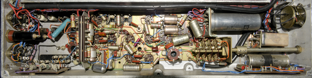
 Above and below: Two views of what I refer to as the Modulator assembly, although it is much more than that ...
This is where I say "I should have remembered to take a 'before' photograph!". I get the impression that this may NOT be the original 'Modulator'. Reason being, this particular MA79H is a relatively 'late model' with serial number 937, yet the Sideband filters are the early 'discrete component' type. The small board between them with the wave-wound inductor is referred to as the DSB filter but in reality is an attenuator whose value is such that it matches the insertion loss of the sideband filters.
As I said, this assembly is really a lot more than just a modulator. In fact, what constitutes the modulator is limited to V9 and V13 in the top left corner of the photograph! From the top right, we have the dual crystal oven with the 5MHz and 5.1MHz crystals and the oscillator-doublers V5 and V19 respectively. Sitting next to them we have the FSK reactance valve, V2. Then we have the ALC stage, V22 followed by Mixer-5, V25 (which for some reason, the circuit diagram calls the 11.6MHz amplifier), where the 1.4MHz base carrier is mixed with 10.2MHz to produce a signal at 11.6MHz. This is then fed to Mixer-4, V8 (see what I mean by illogical designations?), where the 11.6MHz is mixed with 10MHz to produce a signal of 1.6MHz. The output of this circuit is fed through V12 which acts as the CW keyer, (controlled by V16) and then on to V10, which is somewhat confusingly designated Mixer-1, where the 1.6MHz is mixed with the output of the KC/s VFO (3.6MHz to 4.6MHz) to produce an output between 2MHz and 3MHz which is passed through a bandpass filter identical to that found in the RA117.
The large variable capacitor in the centre of the photograph is accessible via a hole in the front panel designate 'C'. This is part of the carrier re-insertion circuit and serves to set the level of Pilot Carrier (typically 6dB down). The other two variable capacitors accessible via holes 'S' and 'M' serve to set the Space and Mark frequency shifts when the mode of transmission is FSK. A fourth variable capacitor (not in the photograph) is accessible via a hole in the 'FINE FREQUENCY' bezel, is used to fine-tune the 5.1MHz crystal (doubled to 10.2MHz) and thus the 1.6MHz signal. Similarly, the Reactance Valve, V2, is used to apply the Mark and Space 'shifts' by slightly altering the frequency of the 5MHz (doubled to 10MHz) signal. Note: When FSK is used, the MA284 must be switched 'OUT'.
Back to the signal path: The 2-3MHz signal is then mixed with 37.5MHz in Mixer-2 to produce a signal between 39.5MHz and 40.5MHz. Finally, this is mixed with the Mc/s VFO to generate the output frequency range of 0 - 30MHz (theoretical) which is limited to 1.5MHz to 30MHz by virtue of design.
Note: Unlike the RA117, the KHz VFO in the MA79 actually tunes in 'reverse'. The block diagram does not make this clear. Thus, when calculating the output frequency it is important to think of the Kc/s VFO as tuning from 4.6MHz to 3.6MHz, thus the output of Mixer-1 tunes between 40.5MHz and 39.5MHz. Subtracting this from the Mc/s VFO, tuning from 40.5MHz to 69.5MHz, is how we get a theoretical range of 0MHz to 30MHz. Component constraints limit the lowest output frequency to 1.5MHz.
Above and right: MA79H N937 undergoing final test. Although Racal's literature gives the level of RF output as 100mW into 75-ohms, it is not difficult to get up to 1W out ... but just how much life that takes out of the EL821 is anyone's guess. These drive units were designed to run 24/7, so it makes sense to keep the output to a moderate level and add gain to the system en-route to the antenna.
The larger of the two photographs shows the level of carrier suppression than can be achieved when DSB is selected. I was driving into a Racal-Dana absorbtion power meter via a 75 to 50-ohm adapter (incurs 6dB loss). The display on the oscilloscope shows the waveform for a DSB signal at 5.5MHz. The power meter has a -23dB monitor output for connection to the spectrum analyser.
Connection to the MA79 is via a 12-way Belling Lee connector at the rear. I was exceptionally fortunate to get my hands on a brand-new mating socket and fashioned a break-out box, allowing me to make the relevant patches and connect the modulation drive. The unit in the bottom right of the smaller photograph is my poor man's MA350 ... more on that in another article.
Warm-up time is, as per the manual, about 1 hour ... after which, the frequency stability is excellent.
As well as re-drawing most, but not all the schematics, I also put together (from three sources) a credible and much more readable technical manual for the MA79G and H. Links to downloadable PDFs of all documents and drawings are below:
Technical Manual ... Includes section on the MA284 and a circuit diagram for the LA255.
Block diagram for MA79G (Fig. 1)
Block diagram for MA79H (Fig. A-1)
MA79G Calibration and Output Stages, (Fig. 3) ... updated May 2025
MA79H Calibration and Output Stages, (Fig. A-5) ... updated May 2025
MA79G Modulation and IF Stages, (Fig. 2) ... updated May 2025
MA79H Modulation and IF Stages, (Fig. A-4) ... updated May 2025 ... Figures 2 and A-4 have been modified to reflect Change No. 2, Issue 6, June 1971. Included in the manual. Note the reference to a -35V line. I have kept to this reference when making changes to the circuit diagrams. This may be a genuine 'typo', or it may be a 'nod' to the fact that the -25V line is nominal and is actually closer to -35V at the best of times.
MA79 Ancilliary Circuits, (Fig. 4)
MA79 Ancilliary Circuits, (Fig. 4), modified ... Updated March 2025 ... Modified to reflect units where three additional HT fuses have been fitted, notably when the LA255 is fitted.
Next post in the series: Poor Man's MA350
- The MA79 Transmitter Drive Unit
- Poor Man's MA350
- Fully Loaded MA79G
- Transmitter Drive Unit Type MA79H
May 2022
Since January 2009, I have stripped and refurbished over 50 Racal RA17s, 17Ls etc. and RA117s. I’ve given the same treatment to several RA137s and 37s and at least one of every Racal sideband adapter … I’ve even got an early MA259 Frequency Standard bearing serial number N1 and an SA97 wobbulator for setting up the infamous 40MHz bandpass filter in the ‘Wadley Loop’.
But until about a year ago, I’d never had my hands on an MA79 Transmitter Drive Unit. It therefore goes without saying then that the last 12 months have been both interesting and a very steep learning curve. Whereas there are thousands of working RA17s out there … how many people do you know who have a working MA79?
At first glance, the MA79 is often mistaken for an RA17. The front panel layout is initially familiar, until you look more closely. Like the RA17 there is no precise description of what it is on the front panel, although the legends associated with some of the controls might give the game away. The inclusion of a headphone jack, on the other hand, might be seen as a tad confusing.
I have just spent the best part of a year, maybe longer, getting to grips with an MA79H. A very good friend who had no less than four untested MA79s asked if I was interested in taking them on as a project. Not being one for turning down a challenge, I said yes, and arranged to pick them up.
An initial survey suggested that I was looking at a couple of MA79Hs, an MA79G (or maybe a D?) and an MA79A-1. Closer examination yielded some curiosities ...
MA79 Ser. 753: MA284 and LA255 fitted but no PL20 (1.4MHz o/p) ... so likely to be an MA79A-1 with an MA284 fitted by mistake.
MA79 Ser. 597: Lavoie crystal oven fitted. No PL15 on rear panel! Also, No L7 audio transformer ... so possibly an MA79D, which had no provision for modulation.
MA79H Ser. 937: No MA284 but did have a dual crystal oven with two 1MHz crystals fitted in its place!!
MA79A-1 Ser. 139: MA284 and LA255 both fitted. MA284 clearly fitted by mistake as the MA79A had an internal frequency standard.
Ideally my friend was looking for two working examples. The MA79A-1 was missing more than a few front-panel components and the input side of the PSU was completely smashed, so it was designated as a spare-parts donor. Serial number 597 was also put aside since it lacked PL15 and the input audio transformer. This left me with serial number 937 which was labelled as an MA79H, and MA79 serial number 753. The MA79H was missing an MA284, but I would use the one out of the scrapped MA79A-1. MA79 Ser. 753 is a curious piece. The lack of PL20 indicates that it has no provision for external modulation (It does have the balanced audio input transformer, L7). So that makes it compliant with an MA79A. Fitting an LA255 is not a simple plug-in job, so it is likely that it was officially converted to an MA79A-1 at a later date. It does have the necessary 'free' D-Type connector and fittings for accepting an MA284. So I will probably go ahead and configure it as an MA79H
Unlike the RA17 series of receivers, and I will include the RA117s here too, where good quality manuals, user and service, are freely available, information on the MA79 is a different matter altogether. I am told that Racal never provided any of the end-users with anything remotely like a Service Manual. With that in mind, you might think that there would be plenty of User Manuals out there, but that is not the case. To date, I have come across only three PDF copies of a User/Technical Manual, none of which are complete … all are missing pages … different pages … and the two largest schematics are literally unreadable to be of any use. One of the PDFs has been produced from a non-loose-leaf copy where the text down the left side of many of the pages is unreadable. Here someone has then written the missing words into the margin, using either a blunt pencil, a child’s crayon or a knackered felt-tipped pen! There is even an official stamp on one of the pages stating that that particular copy is the best quality that is available
Given the complexity of the MA79, I can actually see why Racal did not release the Service Manual to the end-users, but why the lack of good quality User Manuals? We will probably never find out.
Note: As with all Racal equipment of the 50s and early 60s, frequency is 'measured' in Cycles per Second as opposed to Hertz. So, before we go on; Where reference is specifically made to the front panel, I will likely use Kc/s or Mc/s, but where I am describing the circuitry, I will probably revert to KHz or MHz.
So now I had the makings of a refurbishment project. At some point I was going to need to power them up. Somebody once said to me “If you’re going to get an MA79, make sure it’s a ‘G’, as the ‘H’ requires an MA350B Decade Frequency Generator in order run”. It is true that the MA79H does require an MA350B to provide 1MHz and 200KHz signals, but initially I got by using my Adret 740A to provide the 1MHz and my HP3325A providing the 200KHz. Although the MA350B is described as a Decade Frequency Generator, specifically designed to replace the Kilocycles VFO, that feature is not mandatory.
In two of the MA79s that I had chosen for this project, something had leaked a horrible brown sticky substance down the inside of the left side-plate (see image on left). This turned out to be ‘potting goo’ from the AF Input transformer. I can only think that this occurred as a result of the units being stored in a very warm environment. The only way to clean up the mess was to completely remove the metalwork that makes up the left side plate and scrape the 'goo' off with a sharp wood-chisel then use white-spirit to wipe the metalwork clean.
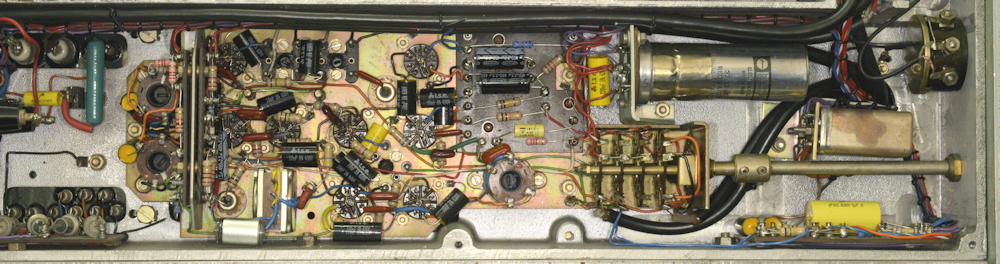
As can be seen from the photograph on the left, much of the underside of the MA79 looks familiar, particularly the compartments that are normally covered by screw-on lids. Indeed, these compartments are more or less identical to those found in any RA17. Even the layout in the PSU area initially resembles that of an RA117, but here, instead of the audio output stages we have the MA79's calibrator sub-assembly ... more on this later.
The MA79 resembles the RA17 in more than looks. It utilises the same ‘Wadley Loop’ drift cancelling technology which right away, makes it that bit more complicated than other transmitter drive units of the day. To be honest though, the MA79 actually has more in common with the RA117, utilising the same frequency conversions, albeit in reverse.
If you think the RA17 looks complicated, take a look at the coax cabling inside any MA79, above the chassis, then count the valves. The basic MA79G embodies no less than 33 valves. The MA79H has 35 since it contains an MA284 Mixer/Amplifier (more on that later). And if you have the LA255 Tone to DC Converter, where a ‘look-up’ of the Nato Stock Number, 5820-99-580-1976, identifies it as ‘KEYER, TONE’, add another two! That’s a possible 37 valves in total. Curiously, the LA255 on MA79 Ser. 753 had been miss-identified as a ‘TONE to DR CONVERTER’; a 'feature' which didn't help trying to figure out what it did.
MA79 PSU (part of) and Calibrators
I make a point of never switching something on unless I am 100% confident that it isn’t going to go bang. A quick peak inside one of the MA79s revealed a ruptured 10nF capacitor (see left) which appeared to be across the primary winding of the mains transformer. I figured it was probably a good idea then to fully refurbish everything in the power supply. But there was a problem. What actually constitutes the PSU in the MA79? The User Manual has a schematic (Fig. 4), entitled Ancilliary Circuits. This is a fairly straight-forward schematic which also identifies three different HT and Heater distribution points, as well as the -25V rail, the main 250V HT rail and a +200V rail.
The downside of this is that as with all the schematics, this one has been reduced and each of the distribution points are given a lower-case letter which is difficult to identify. The two main schematics have both been reduced even further to the extent that considerable detective work … you might call it reverse engineering, is required to work out which distribution network serves which part of the MA79. Unlike the RA17 etc. the components which make up the PSU in the MA79 are literally scattered throughout its labyrinthian chassis. I didn’t stop with the PSU, choosing to err on the side of caution, I ended up giving the MA79H the same refurbishing treatment that I give RA17s etc. I figured that if I was going to have to ‘feel’ my way around the unit, it would probably make my life easier if all the Rs and Cs were the correct value … that’s the theory.
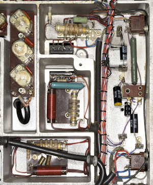
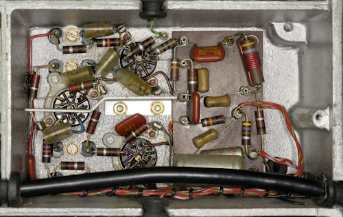
The photograph on the right shows three familiar HT and Heater distribution boards after refurbishment. To the right of these are four capacitors and a wirewound resistor which also form part of the 'distributed' PSU.
MA79 PSU (part of) and Calibrators after refurbishment
With the components in the PSU, and the calibrators (simply because they shared a compartment) replaced with modern types, I slowly powered it up using my big 8A variac. The two 6V lamps lit up and nothing went bang! So I was now ready to check out the MA79 ... But, where to start? A look at the block diagram was initially not very helpful. Like the main schematics, it too has been greatly reduced and badly copied. I decided to look for things that were familiar … like the Wadley Loop … and what exactly is the purpose of the MA284? It was then that I realised that because of the inclusion of the MA284, the MA79H actually has not one but two Wadley loops … How cool is that! Here's how that little extra box works, and why it is there ...
I actually re-drew the MA79H block diagram in such a way that the function of the MA284 was more apparent, and recognisable as forming part of a second 'Wadley Loop'. Without going into too much detail at this point, we need to understand that the basic MA97 relies on three crystal oscillators, running at 1MHz, 5MHz and 5.1MHz. The latter two are doubled to provide base frequencies of 10MHz and 10.2MHz. The 5MHz and 5.1MHz crystals share a common thermostatically-controlled oven which is situated in the Modulator assembly. However, with the use of multiple crystal oscillators comes an inherent risk of reduction in accuracy. A need arose where greater frequency accuracy and stability was required, which is why the MA79H was intended to be used in conjunction with the MA350B Decade Frequency Generator, which replaced the 2nd or KC/S VFO, and the 1MHz crystal oscillator. It also provides a 200KHz signal, the reason for which will become clear. All three of these signals are derived from the MA350B's internal frequency reference. For even greater accuracy and stability, that too could be replaced by the output from an MA259 Frequency standard.
Click here to view the MA79H block diagram.
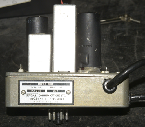
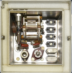
Mixer Unit type MA284
With the MA284 installed, the 5.0MHz oscillator/doubler is disabled. The output of the 5.1MHz crystal oscillator/doubler is fed to Mixer 5 and the mixer in the MA284 where it is mixed with the 200KHz signal from the MA350B to produce 10MHz. In Mixer 5, the 10.2MHz signal is mixed with 1.4MHz to produce 11.6MHz. The 10MHz signal from the MA284 and the 11.6MHz signal from Mixer 5 are mixed in Mixer 4 to produce a super-stable signal at 1.6MHz. Any inaccuracy and/or drift in the 5.1MHz crystal oscillator is completely eliminated in the same way that 1st VFO drift is eliminated in the RA17 etc, and the MC/S VFO in the MA79 for that matter. AND, since the 1.4MHz signal that the 10.2MHz signal is mixed with is ultimately derived from the 1MHz signal from the MA350B, the accuracy and stability of the MA79H, when used in conjunction with an MA350B, is defined by the 1MHz output from the MA350B alone ... absolute genius!
As mentioned previously, I set up two synthesised signal generators to provide the required 1MHz and 200KHz signals. My first task was to figure out a way to test the MA284 and to confirm that it was doing what it was supposed to do, i.e ensure that anything that was 'tweakable' was in the right position.
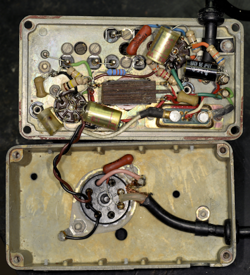
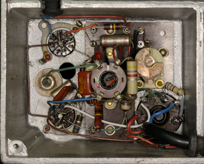
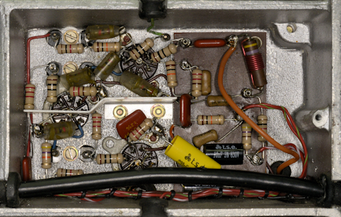
Mixer Unit type MA284, refurbished
Now to see if it would generate any power. A quick referral to the very 'iffy' manual did mention linking pins 3 & 4 and 5 & 6 on PL15 and a couple of necessary front panel settings. This, I did, and things began to happen. I even had a signal at the output, albeit noisy and not in any way related to the frequency that the controls were set to. Then all of a sudden, I had a meaningful output that did relate to the controls and the RF Gain control and ALC even had an effect; my Adret 740A and HP 3325A were clearly doing their thing!
I needed to verify the tuning of the two inductors on the MA284. The tall one clearly had a top core and a bottom core, but the cores had slots rather than hexagonal holes which would have allowed a hex trim tool to reach down through the top core to get at the bottom one. It was a bit tricky lifting the top of the box whilst it was on the main chassis, but I was able to access both cores and connect my spectrum analyser via a suitable isolated probe (coax lead and 100nF capacitor) to TP2 on the MA284. This allowed me to adjust the signal level from the two signal generators for optimum, whilst adjusting L1 (for 10.0MHz) and L2 (a trap to block 10.2MHz) for the best 10.0MHz signal at TP2 whilst minimising the 10.2MHz content. I was able to keep the latter at least 20dB down on the 10MHz product, and that appears to be adequate. I haven't found any specific instruction on setting up the MA284.
The switch in the centre of the MA284 should be set to 'IN' when the TRANSMISSION SELECTOR on the MA97 front panel is set to anything other than F.S.K., when it should be set to 'OUT'. More on this later.
This enabled me to ‘skim’ through some of the features of the Drive Unit, verifying that it would deliver an accurate frequency at the required power over its specified frequency range. It did, up to a point but at times the output signal was unstable and noisy, and the level did vary to the point that it was below spec. at times. If I switched it off for any reason, it was then a struggle to get it working again. There had to be a reason. I did discover that the point on the Octal socket bringing the 1MHz into the MA79 had been taken to chassis via a 68-ohm resistor. The reason for this is that the 1MHz output from the MA350B is designed to drive into 70-ohms. Lifting one end of the 68-ohm resistor did improve the signal significantly.
The failure to ‘start’ problem turned out to be the 100KHz calibrator, of all things. Whereas an RA17 can happily run without a calibrator, the MA79 will simply not function without its calibrator. As said, the calibrator works at 100KHz, 10KHz and 1.6MHz. The 100KHz and 10KHz positions are obvious and are used to calibrate the film-scale. The 1.6MHz part of the calibrator is used to calibrate the Fine-Tune control and/or the Mark/Space offsets. In total, the Calibrator Assembly in the MA79 has no less than eight valves. The reason for this, and why there is a headphone socket on the front is because since the MA79 isn't a receiver, the resulting 'beat frequencies' need to be made audible, by way of a harmonic amplifier (V29), a mixer (V33) and Audio amplifier (V32). The eighth valve is the 100KHz multiplier (V31), providing the basis for the 1.4MHz IF for the Modulator and the 1.6MHz calibrator … a clever use of the existing 100KHz signal.
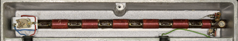
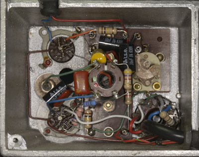
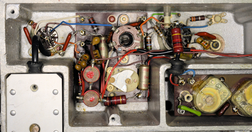
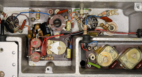
Calibrators, refurbished
Right: The underside of the calibrator module. As in the RA17, the 100KHz signal is produced by 'regenerative dividing' from the base 1MHz signal. This is then used in the same manner to subsequently generate the 10KHz calibration signal. Some RA17s were manufactured with such a 4-valve calibrator giving both 100KHz and 10KHz calibration points.
A Regenerative Divider, or Miller Frequency Divider, mixes the input signal with feedback from a multiplier. It operates in a similar way to an injection locked oscillator. Theoretically, division by any integer value is possible. In the MA79 100KHz calibrator, the 1MHz signal is fed into the divider stage (V27) which is tuned to 100KHz. A sample of this output is fed to the multiplier stage (V28) which generates the 9th harmonic, 900KHz. This is then fed back to the divider stage where it is mixed with the 1MHz signal thus ensuring that the output of this stage is exactly one tenth of the 1MHz input.
Should the desired output frequency be 200KHz, the divider stage would be tuned to 200KHz and the multiplier stage tuned to 800KHz. In the case of the MA79, the 10KHz calibrator works in the same way, but in this case, the input is 100KHz, the divider is tuned to 10KHz and the multiplier stage is tuned to 90KHz.
To be honest, Racal's regenerative divider is perhaps the most maligned circuit when discussing RA17s etc. I know of several users who have had so much trouble with the circuit that they have simply removed it. I will confess that although I have never encountered a problem with the calibrator circuit that was not the result of a hard fault, I can testify that for some unknown reason, some calibrators result in a weak, insipid calibration tone whilst others produce a healthy tone. I will also testify that following the detailed initial alignment procedure in the RA17 manual, it is ALWAYS necessary to adjust the tuned circuits slightly off peak to ensure reliable starting ... and the same is true for the MA79. In fact, finding the core positions which resulted in reliable starting of the 100KHz divider required several trial and error iterations. Having achieved this, the MA79H was now producing a healthy and accurate signal across most of its range. So back to checking and verifying the various features ...
But first; a brief synopsis of these features ...
Considering that the MA79 dates from the early 1960s, what it achieves is really very impressive. It can generate AM (full or reduced carrier), Double Sideband (Suppressed or Reduced carrier), Single Sideband (L.S.B. or U.S.B.), CW and F.S.K. (Frequency Shift Keying). All this with a frequency accuracy and stability like the RA17 or better, thanks to the use of Trevor Wadley's ingenious drift-cancelling system. Despite the fact that the power output is only specified as 100mW, a well aligned MA79 is capable of delivering up to 700mW or more, but this is not advised as the life of the output stage will be compromised and the grounded-grid EL821 runs very hot under normal circumstances anyway.
Not all MA79s were made equal ...
Without describing all the variations; To give some examples; The MA79A had no provision for external modulation, i.e. it did not have a 1.4MHz output or a 1.4MHz input. The MA79D was CW only ... and presumably F.S.K. also, but I cannot confirm this.
Although the MA79H was now 'starting' reliably, and delivering what was potentially a good signal, I was still concerned that there was a discernible, albeit low-level amplitude modulation visible on the carrier wave. This was by chance traced to the Cathode Follower on the AF input to the Modulator, or rather the unused half of the 12AT7. Someone had cleverly used what was the unused half of V6 (12AT7) to construct an audio preamplifier and 'slotted' it in between the balanced input transformer and the cathode follower. It actually worked very well but because of its relatively high gain, it was introducing noise into the modulator circuit. I opted to 'take it out' and the noise on the signal disappeared.
So, after a couple of false starts, I was now ready to work my way through the MA79H. My plan with this one was to perform a full system refurbishment. For this reason, the two VFO modules would be removed first, just like working on an RA17. Even if not doing a full 'refurb' on the MA79, it is probably wise to consider removing the two VFO modules and replacing all the carbon resistors and paper capacitors anyway since these are the only components in the MA79 which are not readily accessible.
Left: If this were an RA17, it would be referred to as the 1st VFO. In the MA79, it is referred to as the Mc/s VFO. As you can see from the photograph, the inside looks very similar to that of a MK1 or MK2 RA17. The compartment on the right houses the two tuned amplifier stages. The Low Pass filter is identical to that in the RA17. The technical manual does give a fairly detailed description of the various parts of the MA79, and there is even a comprehensive guide to alignment. But where the manuals for the RA17, RA17L and RA117 all give comprehensive details on how to align the pre-selector, there is no such table of frequencies for aligning the tuned circuits either side of the EL821 in the MA79. It would have been be nice to have a starting point. Initially I treated it like an early RA17, which did work, up to a point, but I ended up with double humps in the tuning and at least one range where the maximum output dropped to as low as 50mW. In the end I found the best approach was to perform the alignment close to the 'top' of each range and then go backwards and forwards over the range to smooth out any extra responses. This also resulted in minimum output over the entire range never being less than 100mW.
The following may be used as a 'guide' for aligning the two sets of tuned circuits associated with V26 (E180F) and V31 (EL821).
Set the OUTPUT TUNING to 8, GAIN to MANUAL and R.F. GAIN fully clock-wise, then either inject a signal at TP3 (between V20 & V23) if testing the module alone, or set the MC/S and KC/S controls to the frequencies listed below and adjust each pair of Input/Output transformers in turn for maximum output at PL12, ensuring also that you do not have a 'double-hump' response.
Range
1.5 - 3
3 - 6
6 - 12
12 - 20
20 - 30
1.5 - 3
3 - 6
6 - 12
12 - 20
20 - 30
Frequency
2.5MHz
5.5MHz
10.5MHz
19.5MHz
29.5MHz
2.5MHz
5.5MHz
10.5MHz
19.5MHz
29.5MHz
Input
L39
L41
L42
L43
L44
L39
L41
L42
L43
L44
Output
L47
L48
L49
L51
L52
L47
L48
L49
L51
L52
Trimmer capacitor C168 (6pF) is in parallel with C166 (212pF), which is ganged with C214 (also 212pF). Without wanting to sound cynical, it will come as no surprise that the manual only mentions the existence of C168, but fails to explain its purpose. I can only suggest that it might be there to provide minor adjustment should it be necessary to replace V26, obviating the need to retune all 5 ranges (L39 thru' L44). Thus probably best to leave it set mid-travel.
Mc/s VFO Module, after refurbishment
Close-up of L39 thru' L44, cover removed.
30MHz Low-Pass filter on the output of the harmonic generator.
Above: Before refitting the VFOs, like with the RA17 etc., one of the screws securing the 30MHz LP filter on the output of the harmonic generator is obscured by the MC/S VFO, so whilst the VFO is off the chassis, now is a good time to change the two resistors at one end of the filter.
In the 2nd or KC/S VFO, the VFO (V7, EF91) is based in part on the 2nd VFO in the RA17, however, the module also embodies a 6-channel crystal oscillator (V4, 6AS6). All the passive components are contained within a thermostatically-controlled oven.
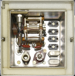
Kc/s VFO Module, underside.
Kc/s VFO, inside of oven.
As said, the actual VFO here is similar to that found in the RA17 and RA17L, although the enclosure bears an obvious resemblance to that found in the RA117, especially the switch mechanism which, in the case of the MA79, is an 8-way switch. This offers the user up to 6 possible crystal-controlled options, Internal VFO, or External (VFO, Synthesiser or Crystal). In this particular case, positions one and two are populated, with crystals for 4200KHz and 3750KHz which translate to x.400MHz and x.850MHz respectively. Unfortunately, I discovered that the heater element for the oven was open-circuit, and since it is bonded to the inner wall of the upper enclosure, it is far from easy to repair or replace. However, since I have two MA79s sitting here which are either beyond repair or of little use (as in the MA79D) I had access to two potential replacement VFOs. Although both turned out to have intact heaters, I ended up using the VFO out of the MA79D as the VFO in the MA79A-1 turned out to be physically damaged beyond economical repair.
Kc/s VFO Module, underside, after refurbishment.
Kc/s VFO, inside of oven, after refurb.
Here's a thought ... I have heard it said that the MA79 is like an RA117, but in reverse. The two main VFOs operate over the same frequency ranges. I read somewhere that since both KHz VFOs tune between 3.6MHz and 4.6MHz, that it may be possible to slave the MA79 to an RA117. However, the KHz tuning in the MA79 is in the opposite direction: The numbers on the scale increase from left to right, as opposed to right to left on the RA117. This is because of the extra conversion stage which 'flips' the tuning. So, much as it sounds like a good idea, it isn't possible to slave an MA79 to an RA117.
1MHz Oscillator/Amplifier.
With the two VFO modules refurbished and their functions verified and aligned, we move on to more familiar ground, and this is where we realise that the inner workings of the MA79 are not all based on the RA117. For instance, what is the 1MHz oscillator in the RA17 is exactly that in the MA79, when running an internal 1MHz source, otherwise the same circuit (V1) doubles as an amplifier when the 1MHz source is external. Likewise, the Harmonic Amplifier (V3) in the MA79 is almost identical to that in the RA17; the difference being, the cathode is taken to ground via 560 ohms. Also, the MA79 used two EF91s here where the RA117 uses a pair of 6AK5s ... but that's another day.
1MHz Oscillator/Amplifier, after refurb.
I have two MA284s in my possession right now. The 'prettier' of the two is in the MA79H. While going through my photographs of this project and looking at the 68-ohm resistor, which acts as a matching load for the 1MHz output from the MA350B. It struck me that whilst one end of the resistor was indeed connected to the point where the 1MHz signal is applied, the other end did not appear to be connected to ground, in the photograph. It was simply soldered to pin 2 on the Octal socket. A quick check with a multimeter confirmed that pin 2 was indeed connected to ground (chassis), implying an internal connection within the MA284. That explains the pink wire in an earlier photograph of the inside of the MA284. Thus when the 1MHz source is internal, the 68-ohm resistor is disconnected. Interestingly, the grubbier and older (Ser. No. 4) of the two MA284s doesn't have this internal wire to ground. Also, there is no link between pin 2 and ground in the adapter lead shown in Fig. 15 of the manual.
Important note: Connecting pin 2 to ground applies only to chassis configured for a Lavoie oven. If configured for a Knight oven, I would expect pin 6 to be connected to ground. See Figs. 3 or A-5, and Fig. A-2 (relates to MA284) in the documentation for more details. Note that these connections are missing from Fig. A-3.
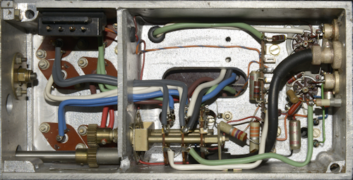
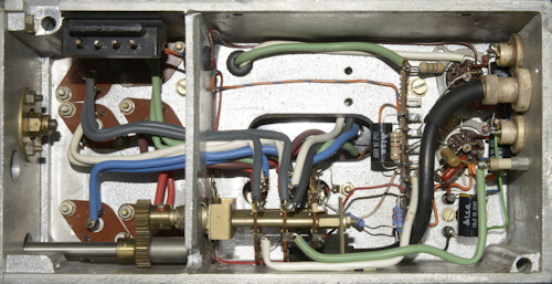
Harmonic Mixer and first two 37.5MHz Amps.
Harmonic Mixer and first two 37.5MHz Amps., after refurb.
The Harmonic Mixer stage and first two 37.5MHz tuned amplifiers are identical to that found in the RA17.
Mixer-2 and third 37.5MHz Amp.
Mixer-2 and third 37.5MHz Amp., after refurb.
Mixer-2 in the MA79 is almost identical to the 2nd Mixer in the RA17 etc. and very likely prone to the same failure, that of the 1K resistor R183, at the bottom of the above photographs. If for any reason, trimmer C87 is inadvertently short-circuited, R183 (1K) will burn out. In the MA79, there is an additional resistor R90 (also 1K) which will also burn out for the same reason ... AND, looking at the photograph on the left, it does indeed look like both R183 and R90 have been replaced. R84 (33R) does not appear in the RA17 etc. and has been omitted from the component layout diagram (Fig. 8) in the MA79. Whilst re-drawing all the circuit diagrams it did strike me that the component designations do not appear to be logical. A case in point being resistors R90 and R183, where although R90 is more or less in sequence with the resistors around Mixer-2, it is actually the one which has been added later and I would have thought it more logical for it to be designated R183.
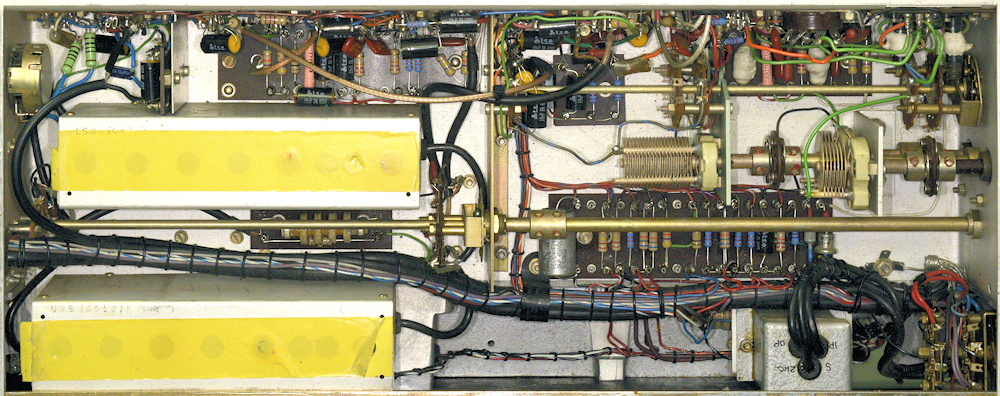
Above and below: Two views of what I refer to as the Modulator assembly, although it is much more than that ...
This is where I say "I should have remembered to take a 'before' photograph!". I get the impression that this may NOT be the original 'Modulator'. Reason being, this particular MA79H is a relatively 'late model' with serial number 937, yet the Sideband filters are the early 'discrete component' type. The small board between them with the wave-wound inductor is referred to as the DSB filter but in reality is an attenuator whose value is such that it matches the insertion loss of the sideband filters.
As I said, this assembly is really a lot more than just a modulator. In fact, what constitutes the modulator is limited to V9 and V13 in the top left corner of the photograph! From the top right, we have the dual crystal oven with the 5MHz and 5.1MHz crystals and the oscillator-doublers V5 and V19 respectively. Sitting next to them we have the FSK reactance valve, V2. Then we have the ALC stage, V22 followed by Mixer-5, V25 (which for some reason, the circuit diagram calls the 11.6MHz amplifier), where the 1.4MHz base carrier is mixed with 10.2MHz to produce a signal at 11.6MHz. This is then fed to Mixer-4, V8 (see what I mean by illogical designations?), where the 11.6MHz is mixed with 10MHz to produce a signal of 1.6MHz. The output of this circuit is fed through V12 which acts as the CW keyer, (controlled by V16) and then on to V10, which is somewhat confusingly designated Mixer-1, where the 1.6MHz is mixed with the output of the KC/s VFO (3.6MHz to 4.6MHz) to produce an output between 2MHz and 3MHz which is passed through a bandpass filter identical to that found in the RA117.
The large variable capacitor in the centre of the photograph is accessible via a hole in the front panel designate 'C'. This is part of the carrier re-insertion circuit and serves to set the level of Pilot Carrier (typically 6dB down). The other two variable capacitors accessible via holes 'S' and 'M' serve to set the Space and Mark frequency shifts when the mode of transmission is FSK. A fourth variable capacitor (not in the photograph) is accessible via a hole in the 'FINE FREQUENCY' bezel, is used to fine-tune the 5.1MHz crystal (doubled to 10.2MHz) and thus the 1.6MHz signal. Similarly, the Reactance Valve, V2, is used to apply the Mark and Space 'shifts' by slightly altering the frequency of the 5MHz (doubled to 10MHz) signal. Note: When FSK is used, the MA284 must be switched 'OUT'.
Back to the signal path: The 2-3MHz signal is then mixed with 37.5MHz in Mixer-2 to produce a signal between 39.5MHz and 40.5MHz. Finally, this is mixed with the Mc/s VFO to generate the output frequency range of 0 - 30MHz (theoretical) which is limited to 1.5MHz to 30MHz by virtue of design.
Note: Unlike the RA117, the KHz VFO in the MA79 actually tunes in 'reverse'. The block diagram does not make this clear. Thus, when calculating the output frequency it is important to think of the Kc/s VFO as tuning from 4.6MHz to 3.6MHz, thus the output of Mixer-1 tunes between 40.5MHz and 39.5MHz. Subtracting this from the Mc/s VFO, tuning from 40.5MHz to 69.5MHz, is how we get a theoretical range of 0MHz to 30MHz. Component constraints limit the lowest output frequency to 1.5MHz.
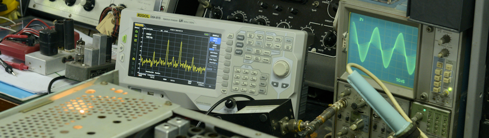
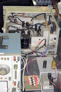
Above and right: MA79H N937 undergoing final test. Although Racal's literature gives the level of RF output as 100mW into 75-ohms, it is not difficult to get up to 1W out ... but just how much life that takes out of the EL821 is anyone's guess. These drive units were designed to run 24/7, so it makes sense to keep the output to a moderate level and add gain to the system en-route to the antenna.
The larger of the two photographs shows the level of carrier suppression than can be achieved when DSB is selected. I was driving into a Racal-Dana absorbtion power meter via a 75 to 50-ohm adapter (incurs 6dB loss). The display on the oscilloscope shows the waveform for a DSB signal at 5.5MHz. The power meter has a -23dB monitor output for connection to the spectrum analyser.
Connection to the MA79 is via a 12-way Belling Lee connector at the rear. I was exceptionally fortunate to get my hands on a brand-new mating socket and fashioned a break-out box, allowing me to make the relevant patches and connect the modulation drive. The unit in the bottom right of the smaller photograph is my poor man's MA350 ... more on that in another article.
Warm-up time is, as per the manual, about 1 hour ... after which, the frequency stability is excellent.
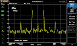
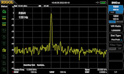
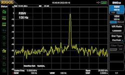
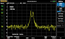
Some spectrum analyser screen-grabs ...
DSB signal.
LSB signal.
USB signal.
FSK signal.
As well as re-drawing most, but not all the schematics, I also put together (from three sources) a credible and much more readable technical manual for the MA79G and H. Links to downloadable PDFs of all documents and drawings are below:
Technical Manual ... Includes section on the MA284 and a circuit diagram for the LA255.
Block diagram for MA79G (Fig. 1)
Block diagram for MA79H (Fig. A-1)
MA79G Calibration and Output Stages, (Fig. 3) ... updated May 2025
MA79H Calibration and Output Stages, (Fig. A-5) ... updated May 2025
MA79G Modulation and IF Stages, (Fig. 2) ... updated May 2025
MA79H Modulation and IF Stages, (Fig. A-4) ... updated May 2025 ... Figures 2 and A-4 have been modified to reflect Change No. 2, Issue 6, June 1971. Included in the manual. Note the reference to a -35V line. I have kept to this reference when making changes to the circuit diagrams. This may be a genuine 'typo', or it may be a 'nod' to the fact that the -25V line is nominal and is actually closer to -35V at the best of times.
MA79 Ancilliary Circuits, (Fig. 4)
MA79 Ancilliary Circuits, (Fig. 4), modified ... Updated March 2025 ... Modified to reflect units where three additional HT fuses have been fitted, notably when the LA255 is fitted.
Next post in the series: Poor Man's MA350