A High Power UHF Power Meter
5 minute read
September 2007
I was very fortunate to be loaned, on a long term basis, a Tokyo HL-130U solid-state PA for 70cm. Although I have been QRV on 70cm since 1977, I have never had the capability to run more than 30W at any time. This is about to change! My initial concern was that since the PA belonged to someone else, I should ensure that my antenna VSWR was acceptable. My old Pye reflectometer for that band did not cater for power levels above 75W and I was increasingly suspicious of it’s reliability in respect to VSWR indication.
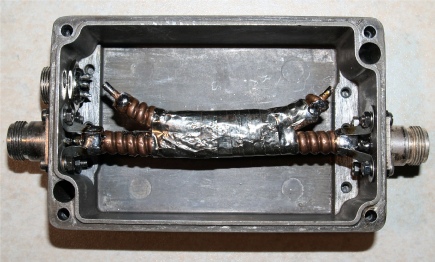
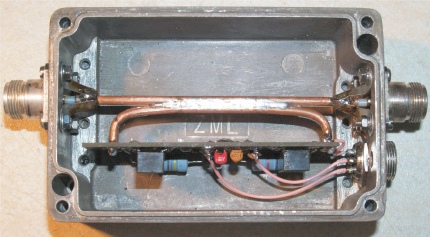
I had read about using parallel lengths of semi-rigid coax to make a directional coupler. I didn’t have any 0.25” semi-rigid but did have some FSJ-2/50 coax. The photograph on the right, I think, explains the construction. The copper outer is filed away on each length of coax over a length of about 45mm and maybe 3mm wide. The corrugation of the outer can be a problem, but with care, it can be done. Bind the lengths together with copper wire such that the openings in the outer are face to face, and carefully bend up the ends of the coupled line. Finally solder the two lines together. I sealed the assembly with conductive tape for good measure. I could have kept it simple and just gone for a single directional coupler, but that would have required turning it around to compare reflected and forward power levels. I didn’t
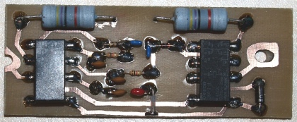
Detector PCB
want to have to do that, so this had to be a bi-directional device, and given the relatively high isolation between lines (~50dB, I’m told), I figured that a little PCB (left) would suffice for ‘swapping ends’. Two miniature relays are used to alternatively connect the 47R resistors or BAT85 diodes to the appropriate ends of the coupled line. One of the relays also selects the appropriate diode output. It is true to say that I could have used just one diode and switched it from one end of the line to the other but since I was planning on separate calibration pots for forward and reverse indication anyway, I included the second diode.
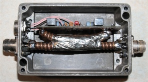
Detector PCB mounted on the coupler
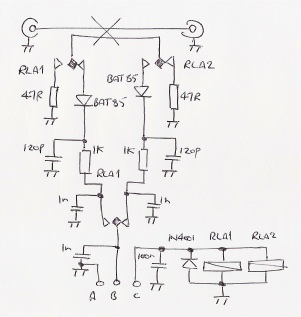
Power Head Schematic
Testing ...
After a slight hiccup which revealed a fault actually inside the 100uA meter, I would have liked to have said that I was satisfied with the results, but something wasn’t right. There was little distinction between forward and reverse power when remotely ‘swapping ends’. So much so that I had to concede that the directivity between the two ports on the coupled line was very poor. The book which had inspired this project made reference to an article in a issue of the RSGB Microwave Newsletter from 04/82. I posted a request for further
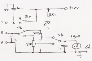
Controller Schematic
information on the UKUG reflector and very quickly received the information that I was looking for. It became very clear that my decision to use FSJ-2/50 coax was nothing less than folly! With no 0.25” semi-rigid coax to hand, I decided to make another coupler out of UT141 semi-rigid coax.
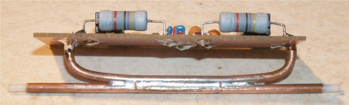
The new coupler (left), unlike the previous, was very easy to make. Clamping the coax in a vice such that only a small area is above the level of the jaws makes it easy to ‘machine’ a 1mm wide slot in the coax outer jacket with a small file. The coupled line needs to be bent in such a way that the mating faces are in good mechanical contact. Initially I used steel wire, tightly twisted around the two lines whilst I soldered them together.
The end result (right) is a much neater and confidence-inspiring assembly. I can also confirm that the new coupler exhibits a far greater level of directivity between the coupled ports to the extent that there is now a very clear distinction between forward and reverse measurements. So much so that although it is possible to ‘cheat’ by adjusting the level at the controller end, very little adjustment is in fact required.
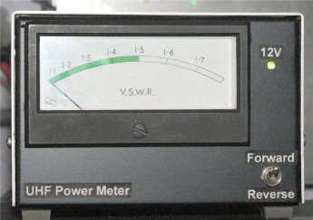
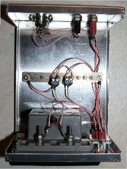
Below are a couple of photographs of the controller ... A fancy name for a simple box.
Below are a couple of photographs of the controller ... A fancy name for a simple box.