GM0UHC is back on 4m
4 minute read
Re-vamping the 4m transverter
October 2006
I last had a 4m QSO back in April 1999. Soon after, I sold my transverter and 3 element beam. Little did I know I’d be back! You see, there was still a spare run of LDF4/50 up the main mast ... And then a friend asked me to look into building him a big solid state amplifier for 4m. This got me thinking. I still had my old 6m transverter, now redundant since I have an IC706 ... and the 6m transverter could easily be modified for 4m, but it would only deliver about 0.5W. I would need an amplifier. My previous attempt at a 4m PA was a miserable failure, attempting to use an arbitrary RF power transistor in a stock design only produced an amplifier that barely delivered 10W when it wasn’t ‘hooting’. This time round I had done some calculations based on G3WZT’s guidelines, and it looked like a single BLY89A would deliver close to 40W from a 13.8V supply provided it was driven properly. My plan of action was divided into four distinct stages. Build an antenna, modify the 6m transverter for 4m then build the PA. Not necessarily in that order. Strictly speaking, the transverter is in fact two transverters back to back. Like all my transverters, the IF is 144MHz. There is an obvious problem with 144MHz when seeking to transvert to 70MHz in that the local oscillator is very close to the desired 70MHz output. For this reason, 28MHz is therefore the IF of choice. Thus we transvert from 144MHz down to 28MHz, then from 28MHz back up to 70MHz.
The 2m/10m transverter during re-test with the pre-selector now mounted at the rear
The 144/28 conversion is handled by G4DHF’s 2m/HF transverter (right), published in HRT back in 1983. I had built it originally with the sole intention of ‘winding up’ CBers ... but I couldn’t get it to work. Later that year, I moved house and all the radios were packed away not to see the light of day until 1988! Then in 1989 with the allocation of 50MHz to the UK amateur spectrum I built the G3WPO 10m/6m transverter and used the now mysteriously working 2m/HF transverter (on 28MHz) to drive it.
The 2m/HF transverter was originally built into two back-to-back die-cast boxes, which in 1989 was satisfactory. However, my plan was to build both transverters into a single unit using two back-to-back aluminium enclosures like my 13cm transverter and 300W HF amplifier. Thus the DHF transverter was duly gutted and rebuilt into a single box having first removed the LOs for 20m and 15m, the 20m LP filter and associated relays. Incidentally, when I graduated from GM8LWR to GM0UHC in 1993, I worked all over Europe using this ‘wee’ transverter.
The 10m/4m transverter with the BLY89A PA.
The task of modifying the 6m transverter for 4m involved replacing most of the Toko S18 type inductors and a fair number of capacitors, not to mention the crystal. Initially, since Toko do not appear to manufacture the so-called S18 range any longer, I thought it would be difficult to obtain the necessary replacements, but in the end I found two UK suppliers. Like my original 4m transverter which was a home-brew ‘Chinese copy’ of the WPO board by Cirkit, the modified transverter appears to out-perform the 6m version on both transmit and receive. According to the data sheet, the BLY89A has a power gain of around 16dB at 70MHz and a typical efficiency of 75%.The PA DC-input power is a little over 40W, and at 75% efficiency, this equates to 30W o/p, which assuming a device power gain of 16dB suggests that the transverter itself is delivering 750mW. I am reliably informed that the signal sounds good too!
Click the play button below to hear what it sounds like on air.
Click the play button below to hear what it sounds like on air.
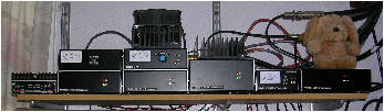
Left to right - 2m linear (80W), 4m (30W), 13cm (50W), 23cm (30W), 9cm (15W), 70cm (10W) and Bobby
For an antenna, I made a simple light-weight 3-ele affair with gamma-match which is mounted between my 25-ele on 13m and 3-ele on 6m. Nowhere near optimum spacing but it works!