My philosophy regarding refurbishing RA17s
52 minute read
August 2025
To date, I've refurbished around sixty RA17s and associated variants, and it is safe to say that I can almost 'do' these in my sleep. However, I've just finished an RA17L from 1962 which really kept me on my toes. This one was full of surprises, and as I hadn't intended doing a write-up on it, I don't have any photographs of it before I stripped it down.
I frequently receive emails from RA17 owners who are either themselves refurbishing one or are in the process of repairing one. Often they are simply writing to acknowledge what I do and to let me know that my articles have inspired them, while others might be seeking help with a tricky problem. Either way I appreciate these emails and it is most gratifying to read how much my efforts have inspired and helped so many RA17 enthusiast.
My initial encounter with an RA17 left me very unimpressed. The owner had been most enthusiastic, describing it as a 'classic' and that the performance was 'legendary'. To me, it was noisy, deaf, and smelly. As I was short of space at the time, I politely handed it back. Years later when I 'inherited' it, I had been inspired by Peter Holtham's (now deleted) blog on his RA117 total strip-down and re-build. That was back in 2009, and I've been refurbishing RA17s and the like ever since. Like Peter, I replace all the carbon-composite resistors and all the tubular paper capacitors. Some will think this unnecessary, but after sixty RA17s through the workshop, I can confirm that the effort is definitely worth it ... and, I can remove and replace these components quicker than it takes to isolate and test them.
So, I thought it might be a good idea to write an article on how I go about aligning these receivers and why my method differs from that in the manual. Also, I will endeavour to highlight as many of the possible issues that one could expect to encounter whilst bringing an RA17 back to life.
We start with a close examination of the receiver ...
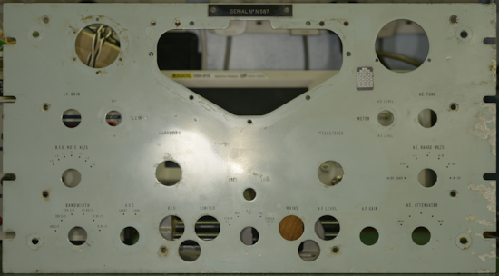
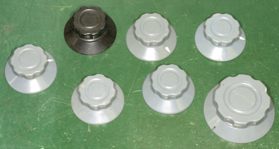
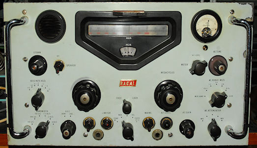
It isn't unusual to find the occasional knob in the wrong place, but in this case no less than seven of the knobs on the front panel were actually wrong. Six of these looked like they might have come from a piece of Marconi test equipment.
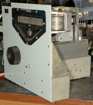
The front panel was in terrible condition, with several square centimetres of paint chipped off and several deep ugly scratches. It was questionable if the handles were genuine as both had been painted silver, the 'shoulders' were missing and it turned out that the threads for the screws were metric, not BA threads. I was told it was an RA17L, but straight away I could tell that the front panel was from an RA17, a MK2, if the serial number on the front had any bearing.
Three of the toggle switches didn't look right. The mains switch was not original and the nuts retaining the Speaker and Meter switches were grey plastic! The Ernest Turner meter had been replaced with a modern square type.
And, I was still yet to take the covers off ...
Often an RA17 turns up without a top cover, and occasionally the bottom cover can be missing. This one came with both covers, so that was a plus. Once these were removed, I noticed that a previous owner had replaced ALL the Hunts tubular capacitors, with one or two exceptions. Also, it was clear to my 'experienced eye' that many of the screws holding the receiver together were wrong. Most noticeable was the use of cross-head, or Phillips screws on the individual compartment covers, some of which were very bright, which made me think that they might be M3 ... and an M3 screw will not go into a 6BA thread without considerable persuasion. The serial plate confirmed that his was indeed an RA17L with Serial Number N6065 and the year of manufacture was given as TB, which is February of 1962
As well as the front panel being from a MK2, distinguishable by the range of Filter Bandwidths and BFO scale, I also noticed that the shaft on the BFO control was NOT a reduction drive ... so was the 100KHz IF strip the correct type?
Something worth mentioning here is that almost all removeable assemblies in the RA17 (and RA17L etc.) will have a serial number written on them somewhere. This includes the Crystal and LC filter modules, the two VFOs and even the small 'rear panel' on which the serial plate is attached. These serial numbers will not necessarily match that on the serial plate, but they do serve to indicate if a sub-assembly has been replaced, if for instance there is a marked difference.
In this case, the 100KHz IF strip was marked 6219, thus likely original, and the crystal and LC modules were marked 6918 and 6919 respectively. Lifting the lid off the crystal filter revealed four crystals, confirming the 300Hz and 100Hz bandwidths for an RA17L. MK1 and MK2 RA17s have three crystal filters and thus this module would then have six crystals fitted. A quick look at the top of the BFO module revealed a serial number of 780 ... definitely removed from an RA17 MK2 ... why?
It always amazes me, the ignorance (and I don't mean that disrespectfully) that some RA17 owners exhibit regards the differences between the RA17 and the RA17L. RA17s can be classed as MK1s, which might include all early production models up to serial 510, although the jury is still out on that. MK2s are all the others up until the introduction of the RA17L which can be considered a MK3. All variations thereafter are still MK3s with the exception of the RA17N from which the RA117 was developed ... more on that later.
For now, here is a list of external differences relating to the RA17 and RA17L ...
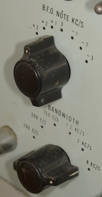
Early MK1 receivers will have the early 'bat wing' knobs on the rotary switches and BFO (see left). Note that the BFO range is +/- 3KHz with no reduction drive.
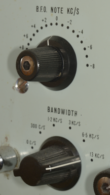
RA17Ls and thereafter will have the later style of knobs (see right). Note that the BFO range is +/- 8KHz and that the knob is a two-part affair incorporating a reduction drive.
MK2 receivers will look very similar to MK3s with the exception that the BFO range and filter bandwidths will be like that on the MK1. The BFO knob might be different. I have seen some where the knob is the same as the filter B/W switch, and others where the knob has the same profile as that on the MK3 but without the moving disc.
Note the difference in filter bandwidths between the RA17L (right) and those that preceded it (left). A quick check is to look for the widest bandwidth, where 8KHz is a good indicator of a MK1 or MK2 and 13KHz indicates an RA17L etc. Other filter bandwidth combinations are available ... but far too many to list.
Very early RA17s might have knurled tuning knobs, like the one in the photograph on the right.
The only other external differentiating feature can be found on the serial plate at the rear. MK1s will be labelled RA17, MK2s will be labelled RA17 MK2 and all the rest will be labelled as RA17L, RA17W etc.
Back to RA17L N6065 ...
As I said, a previous owner had judiciously removed almost all the 'Hunts Horrors' capacitors and replaced them with modern types ... although I think that might have taken place thirty years ago. However, rather than replacing old axial capacitors with modern axial types, they had fitted radial types ... functional, but not so neat. Also, it was clear that most of the 50nF capacitors had been replaced with 68nF capacitors. Since 47nF capacitors are the modern replacement for 50nF and are readily available, I believe that perhaps an abundance of 68nF capacitors had been at hand. The difference in performance would have been nil, but I prefer to keep all replacement components as close as possible to the original.
Several of the original carbon resistors had also been replaced. These were likely ones that had shown external signs of stress. Some had been replaced with wrong values and this I found worrying. There are three possible reasons why a 'wrong' value might be fitted. Perhaps the owner didn't have the correct value at hand so simply fitted the next resistance value in the series ... not likely to cause big problems, but also not really a good idea. Another reason might be that the original resistor was so badly cooked that the colour bands were mis-read. I've done that at least once. The third reason, and I've seen this on a couple of occasions is where Racal had fitted two 1K resistors in parallel to spread the power dissipation, and someone has then fitted a suitable 470 ohm resistor in their place. Yes it works with zero change in performance, but the moment you replace a parallel pair with a single resistor, the physical circuit then differs from the schematic. Always replace parallel pairs with parallel pairs, it avoids confusion.
New components are easy to spot, and I couldn't help noticing that the two 10 megohm resistors in series, connected between the AGC line at V3 (EA76) Anode and the +220V rail, had been replaced with two 1 megohm resistors. Why would anyone do that? Firstly, these resistors are in a very stress-free part of the circuit. Even if for some reason C159A or C159B had gone short-circuit, the resulting power dissipation in each resistor would only be in the region of 2.4mW. So why replace them? I will probably never know.
What purpose do these two 10 megohm resistors serve? Curiously, Racal's description of the AGC (AVC) circuit in the RA17L manual is identical to that in the RA17 manual. i.e. they never bothered to update Part 1, Section 5 of the manual, the Detailed Circuit Description, to reflect the updated AGC circuitry in the RA17L. However, I remembered reading an excellent description of the latter but couldn't remember where I'd found it ... until I found my own notes referring to the same circuit in the RA17W, which I apparently found in a discussion on the UK Vintage Radio Repair and Restoration forum. Here is the essence of that explanation ...
In the original RA17, V24 (or MR8) does not appear: AGC is applied to the 1st IF amp. (V14), 2nd IF amp. (V16) and IF O/P (V17) only. There is no AGC voltage applied to the RF amp. (V3, E180F) at all. Consequentially the RF amp. could easily be overloaded - especially when the receiver is operated in close proximity to an associated transmitter.
The RA17L (and RA17W) which uses a cascode RF amp (ECC189) - however does have AGC applied to this stage - which, of course, circumvents this overload problem. However, to optimise the S/N ratio, the AGC voltage on this RF amp. is only required to 'come on' for large signals. Hence, by biassing the AGC line to the RF amp. slightly positive - by the action of V24 and the two 10M-ohm resistors, which are connected to HT+, the -ve AGC line will have to become significantly large to overcome this +ve bias. That is, it will only go -ve for really strong signals, so the RF amp. becomes the last stage to have its gain reduced under these conditions. Note that R91A (470K) substantially reduces the possibility of this +ve bias upsetting the -ve AGC voltage that is applied to the 100Kc/s 1st IF amplifier. In the RA17L, this is the ONLY IF stage to which AGC is applied.
Thus, the two 10 megohm resistors form part of a potential divider which ensures that the AGC to the RF amplifier stage is held slightly positive until the actual AGC line becomes negative enough to overcome it. Therefore replacing these two resistors with two 1 megohm resistors changes the characteristic of the potential divider resulting in an even higher +ve bias. It is highly likely that this mistake meant that the gain of the RF amplifier was never affected by the AGC. When I refurbished the 100KHz module, I fitted two 10 megohm resistors.
These days when I take on an RA17 refurbishment job, I don't bother switching on the receiver to see if it works. The first thing I do is strip it down to its individual assemblies. This involves removing the front panel and the two side panels. Everything that is removed is then carefully stored in a series of boxes and any fixings (screws etc.) are stored in a separate partitioned box with individual compartments allocated to different assemblies. This way I can ensure that what comes out, goes back in (as long as it is correct!). This was when I realised that RA17L Ser. N6065 had clearly been stripped down and then reassembled ... but not before many of the associated fixings had been lost. The front and side panels are normally secured using counter-sunk screws. Half of the front panel screws were not the originals and about half of those securing the side panels were NOT counter-sunk.
When I removed the two VFO modules, I found that in both cases the bottom cover was missing, which implied that at least 15 6BA screws were missing ... and not only that, one of the long 2BA screws that secures the 2nd VFO to the chassis was missing. Two of the 4BA screws securing the 100KHz module were missing ... and the top cover over L70 and L75 on the calibrator was missing. I suspect that this RA17L lay in pieces for quite some time! ... long enough to loose bits of it.
There was no 56K resistor in series with the AGC at the connection to the 1st VFO module, nor was there the associated ceramic stand-off. The addition of this resistor is the subject of Modification Instruction 11, issued in September of 1965. The fact that Mod 11 is not struck through on the Mod Strike Label at the rear may suggest that this receiver 'slipped though the net' to the extent that this mod was never carried out.
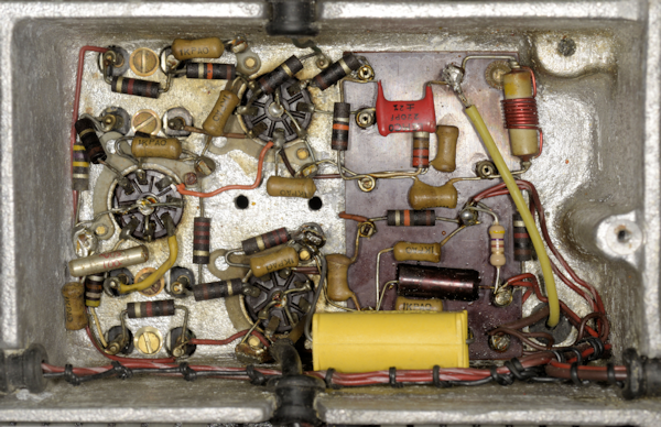
Up to this point, the only other major issue that I discovered was that the aluminium screen which divides the Harmonic Mixer/37MHz Amplifier compartment was missing; as can be seen in the photograph on the left. Also in this compartment, the orange wire connecting V4 pin 4 and V6 pin 3 is confusing, since in these receivers, orange is traditionally associated with Screen Grid circuits. This should be a brown wire as it is part of the heater circuit.
It is probably worth pointing out here that the heater wiring for V6 is not as per the schematic since pins 3 and 4 are swapped. This is the case for ALL RA17s.
At risk of sounding pedantic, the yellow wire from V6 pin 5 is the wrong type of wire and the wrong gauge so likely not original. The capacitor decoupling V6 pin 7 to ground is the correct value (1nF) but should be ceramic. The big yellow capacitor at the bottom is 0.5uF and connected across the heater supply in this compartment. For authenticity's sake, this should be 0.22uF.
It is worth saying here that taking an RA17 or any of its variants apart is a tedious affair. The side panels are easy enough, but to remove the front panel, ALL the knobs must first be removed. Thereafter, the wires to the meter must be disconnected, and probably also remove the meter toggle-switch from the panel since the wires are just that little bit too short for comfort. You could also remove the Speaker-switch at this point but it is just as easy to de-solder the two wires from the centre pins. Only then can the panel be put aside. For some reason, the rear of the front panel of this receiver had been painted a metallic grey colour ... never seen that before.
Frustratingly, the 1st VFO module cannot be removed from the chassis unless the 2nd VFO module is first removed ... and neither can be removed until the Calibrator is removed first. Fortunately this is the easy bit. Removing the 2nd VFO is not so easy. The first thing to do is turn the chassis upside-down and remove the covers from the 40MHz filter. There will be a red wire and an orange wire from the 1st VFO going to one end of the filter. Convention dictates that the red wire should go to the tag closest to the front of the receiver. Next, remove the yellow wire from the 1st VFO where it connects to the junction of L20 and C42 adjacent to the Harmonic mixer (V4).
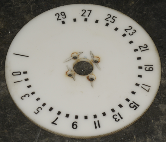
Disconnect the HT and Heater wiring from both VFOs and remove the coax from the Aerial Attenuator that feeds up through the chassis to the RF amplifier. Now you can disconnect the three coaxes to the 2nd VFO module. The plastic MHz disc must be removed before the 2nd VFO can be removed (See the photograph below). This is more fragile than it looks. Why on earth had someone found it necessary to do that to get the four 6BA C/SK screws out?
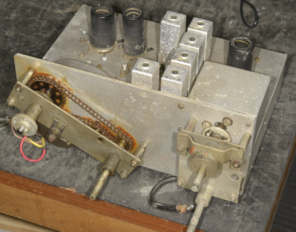
Both VFO modules in the RA17L are secured by three 2BA screws. On the 1st VFO they are obvious ... but not so the 2nd VFO. One is at the rear left corner. A second shorter screw can be found at the front left corner where it goes through a small lug. This screw does NOT feature in MK1 receivers. The third is hidden inside the module itself, and to gain access to it, the top cover of the module must be removed ... requiring the removal of no less than sixteen 6BA CH/HD screws! After which, the last 2BA screw will be found front-right. Withdraw all three screws and carefully lift the module up then slide it forward. This is why the MHz disc must first be removed. Now you can do the same to remove the 1st VO module. In this case, the 1st VFO module was not a pretty sight (see the photograph below). Most of the screws securing the Pre-Selector tuning capacitor cover were missing and there was a heavy rust residue from the Meccano chain and gears encrusted on the front aluminium plate.
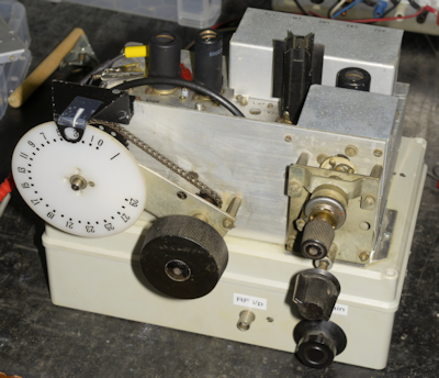 The 1st VFO module actually comprises four circuits: A passive Pre-Selector covering 500KHz to 30MHz in 6 switchable bands, a wide-band RF amplifier, the 1st VFO covering 40.5MHz thru' 69.5MHz and the 1st Mixer stage. All of this can be tested and/or aligned off the main chassis. Racal produced their own bespoke test jig for this purpose. Since designing 'special' test equipment was latterly my job at Racal Defence, I made my own test-jig for the 1st VFO module. This test-jig can also accommodate the RF output module for the MA79, as shown in the photograph on the right.
Although Part 2, Section 5 of the User Manual does provide an alignment procedure, I prefer to refer to EMER E724 when aligning RA17s etc. This document can be obtained from the manuals section of The Wireless-Set-No19 Group.
Bear in mind that when these procedures were written, test equipment was somewhat less sophisticated than what many of us have at our disposal today. Oscilloscopes with a bandwidth in excess of 10MHz were few and far between. Thus a lot of measurements call for an (rms) Valve Voltmeter, but there is no mention of input impedance. I have a Marconi TF.1041B which would be appropriate, with an input impedance of greater than 5 Megohms.
I've also got a Racal-Dana 9301A true rms Voltmeter ... a superb bit of kit, BUT unfortunately the input impedance is 50 ohms, so not appropriate in this case. However, these days, an oscilloscope with a Y-bandwidth of 100MHz is considered quite modest. Thus, when the procedure refers to a reading on the 'valve voltmeter' it is just a case of taking the peak-to-peak reading from the oscilloscope and multiplying it by the reciprocal of 2 x root 2 (or 0.353). Using an oscilloscope also has another benefit ... you can instantly see the shape of the waveform, which can often alert you to distortion or noise issues.
When aligning the 1st VFO module, I start with the Pre-Selector. This part of the procedure actually tests the RF amplifier as well as the Pre-Selector. My signal generator (Adret 740A, or 7100D) is obviously connected to the RF input, whilst my oscilloscope (Tektronix 7603 with 7A26 Y-plug-in) is connected to TP2. I will be honest, I don't actually pay too much attention to the voltage swing at TP2, other than to verify that there is appropriate gain. I find that if the output from the RF amplifier is in the right 'ball park' for the prescribed input level, then all is well.
If you find that there is no signal at TP2, check the continuity of the Low-Pass filter. I know of two occasions where one of the series inductors has failed open circuit for no obvious reason. My theory is that both these failures were the result of too much tension where the thin enamelled copper wire is wound round one of the sixteen pins along the length of Tufnol tube during manufacture.
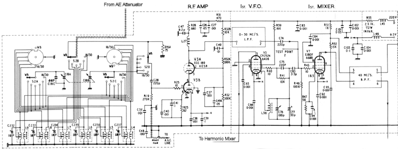 RA17L VFO1 Schematic
Note that the preselctor in the RA17L comprises six double-tuned transformers, each of which contains two ferrite cores. Both windings are resonated by a separate ganged variable capacitor and a tubular trimmer capacitor on each primary winding provides fine adjustment at the high end of each range. The alignment procedure calls for the low end of each range to be set first, yet Racal do not suggest an initial setting for the individual trimmer capacitors. When aligning each of these at the low frequency end, it is important to remove the top core first. This will reduce the output at TP2, so the sensitivity of the oscilloscope will need to be increased to about 10mV/div. Then adjust the bottom core for a peak in amplitude. This will be small and will be found when the core is close to the bottom of the former. There is no risk of screwing the bottom core so far that it falls inside the module, but you will need a long non-metallic tool. Then re-fit the top core and adjust for maximum amplitude again. The cores should NOT touch. On each range, the single tubular trimmer capacitor is then used to peak the response at the top end of the range. Obviously the inductance and capacitance settings are co-dependant. Thus the final setting for the trimer capacitors will depend on the transformer cores and vice-versa. If you find that the capacitor is either too far "out" or fully "in" and still not providing a discernible peak, then it might be necessary to set it mid-travel at the high end then re-adjust the transformer at the bottom end.
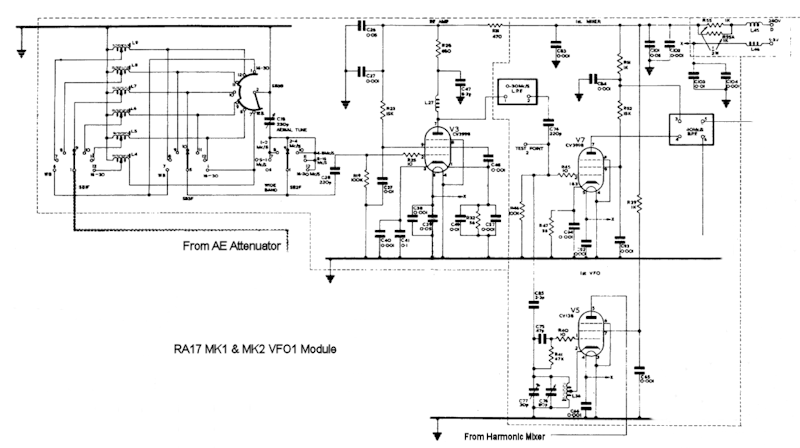 RA17 VFO1 Schematic
The preselector in the MK1 and MK2 RA17 is significantly simpler than the RA17L. Each of the six bands is covered by a single-tuned tapped inductor resonated by a single variable capacitor. Alignment is carried out at a single frequency on each range ... and this time it is possible to screw the core so far that it can fall inside the module. This is why we align the preselector on the bench, not on the chassis. The other obvious difference between the RA17L and the RA17 is that the latter employs a pentode as the RF amplifier whilst the former employs a cascode-configured double triode.
Next we come to the VFO. As part of the refurbishment process, there are two things that I always do with respect the VFO. One is to remove and clean the small trimmer capacitor C77 (30pF). This little capacitor is used for setting the high frequency end of the VFO and is accessible through a hole in the top of the module. Inevitably dust and other contaminants, depending on the environment, can find their way into the space between the vanes and seriously change the value of capacitance. I once had one which measured more than 100nF! Consequently the VFO will not run, and if you find this out while both VFOs are on the chassis, you will need to remove the 2nd VFO before you can remove the 1st VFO in order to clean the capacitor. I learned this the hard way. The second thing I do is ensure good contact between the rotor of C76 and the chassis, as any form of contact uncertainty can result in noise when tuning or in some cases cause the VFO to stop oscillating. Eliminate the likelihood of these issues before screwing the lid back on the module.
Caution!: It is imperative that before aligning the VFO, verify that when the MHz disc is fully counter-clock-wise, the 'zero' calibration mark which is the vertical line to the right of the figure zero, is in line with the MHz cursor. This should also coincide with C76 being not quite fully meshed. If not, the hub that the disc attaches to will need to be rotated. This requires that two 0.005" Allen screws be slackened off. Heat may need to be applied in order to 'unlock' these. DO NOT apply heat when the disc is in place. Also be aware that the markings on the disc are very likely water-soluble ... crazy!
In the past, measuring the frequency of the 1st VFO (40.5MHz to 69.5MHz) could be a tricky affair, as attaching any test equipment to the output of the VFO inevitably led to the frequency being 'pulled'. The original procedure called for a wire loop to be placed around the valve (V5), then connected to a frequency counter. I always found this method tricky as even then, the frequency was still influenced by the test equipment, making calibration of the MHz VFO fraught with uncertainty. However I recently found that my very affordable Tiny SA Ultra is probably the best tool around for this purpose. I simply set it to scan 40MHz to 70MHz, fit the telescopic antenna to the input and set it in the vicinity of the VFO. There is no need to enable to LNA either. The display will show the VFO signal and can be set to identify the frequency. This way I can calibrate the VFO in minutes and have the confidence that no further adjustment will be required.
Finally we have the 1st Mixer. No alignment here ... it either works or it doesn't ... and in sixty RA17s, I've yet to find a fault here that wasn't a duff E180F ... and since I test every valve before I get to this stage, it always works. As with the VFO, something like the TinySA will make your life so much easier. The 1st mixer is an up-converter i.e. the 1st IF is higher than the input. In this case, the IF is 40MHz. So you need to set the spectrum analyser to sweep either side of 40MHz. Set the sweep to something like 1MHz. Choose a MHz, i.e. set the MHz dial to 5 and then apply a 5MHz signal of about 30mV emf to the module RF input. This should result in an output at 40MHz on the spectrum analyser. This can be verified at frequencies across the range of 1MHz to 29MHz.
Finally, and this might be amusing. The second RA17 that I refurbished was a MK1 RA17. Thus the RF amplifier in the module was based around an E180F or CV3998. When I opened it up, R28 (680R) was toast. I mentioned this to the owner (a good friend of mine) and he laughed. According to him, the person from whom he got it had made a rather uninformed and ultimately unwise decision ... based on the fact that RA17Ls were 'better' than RA17s ... and since RA17Ls used ECC189s in the RF amplifier, replacing the E180F with an ECC189 would improve the performance ... hmmm? ... moving on ...
 Simpler than the 1st VFO module, the 2nd VFO, or KHz VFO, is sometimes referred to as 'the Interpolation Receiver'. This module incorporates a very-stable oscillator which is tuneable over the range of 2.1MHz to 3.1MHz and a mixer stage. As with the 1st VFO module, Racal also made their own in-house test-jig (see the photograph on the right) which can also accommodate the 2nd VFO for the RA117 and the KHz VFO for the MA79. Technically, this test-jig only provides a means of verifying the oscillator.
On it's own it does not provide a way of verifying the operation of the mixer stage. Testing what is the 3rd mixer in the RA17, requires another in-house test-jig used for testing the 100KHz IF strip, and a working IF strip. Since testing the latter is a simple matter when it is part of the receiver, I choose to forego testing the 3rd mixer on its own. Like the 1st Mixer, the 3rd Mixer is so simple that I have yet to encounter one that didn't work.
The tuning mechanism of the VFO employs a factory-sealed inductor ... i.e. the inductance cannot be varied. The variable capacitor which tunes the oscillator is third from the front of the 4-gang capacitor assembly. The other three ganged variable capacitors are configured as a tuneable band-pass filter between the 2nd and 3rd mixer stages. Thus at this stage in the alignment process, the only adjustments that need to be made are to set the VFO frequency by way of the trimmer capacitor C136 or to physically move the film scale.
At this stage, I refurbish several under-chassis parts which would otherwise be difficult or even impossible to access whilst their retaining screws are obscured by one or other of the two VFOs. These parts are the Aerial Attenuator, the Meter Rectifier and the two resistors on the end of the 30MHz Low-Pass filter which follows the Harmonic Generator. Only then do I re-fit the two VFOs and remove the 100KHz IF strip in order to refurbish it.
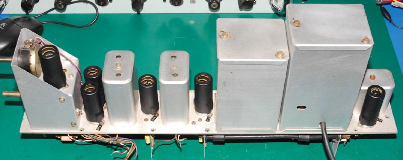 Typical RA17 IF module.
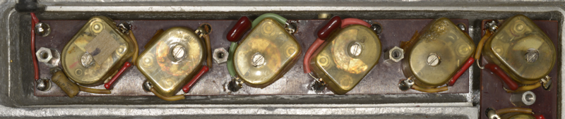
In terms of component count, the 100KHz IF strip is the largest single removable assembly in the RA17. It comprises a two-stage IF amplifier, an IF buffer stage for driving external side-band adapters, an AGC generator and distribution circuit, two filter modules and the BFO.
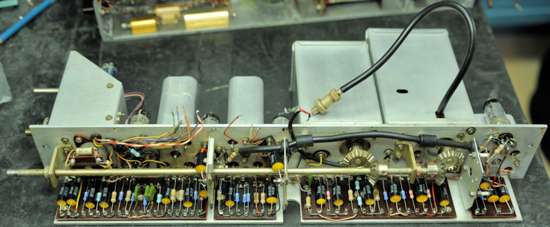 Typical RA17L IF module, underside.
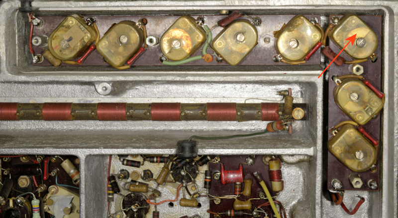
With reference to the photograph above, the tag-boards are, from left to right, AGC and Detector, two-stage IF Amplifier, AGC Distribution, and finally the IF output Buffer stage.
As you can see, there are no less than twenty tubular capacitors, originally by Hunts, which get replaced when I do a refurbishment. Statistically this assembly yields the worst-case out of spec. resistors, especially from the IF amplifier stages, where the resistors are frequently so badly cooked that I can't read the colour bands. 'Leaky' decoupling capacitors are invariably the cause.
The BFO can be tested on the bench. Do not be alarmed that the waveform is so clipped that it is almost a square-wave. The 100KHz IF strip will be aligned as part of the fully assembled receiver ... so now is the time re-fit it and the front panel, in that order.
The procedure in the manual for aligning the IF amplifiers is excellent from a diagnostics point of view, but I admit that I haven't had need to use that method for some time. Instead I have adapted that procedure to involve my Rigol Spectrum Analyser and Tracking Generator. V12 is removed and a connector is inserted into the socket to allow the output of the tracking generator to be connected to pin 5 via a 100nF isolating capacitor. The input to the analyser is connected to the junction of C193 (100pF) and V18 pin 7, again using a 100nF isolating capacitor. Initially I configure the the analyser and tracking generator to operate over a range of 80KHz to 120KHz, and find that the output of the tracking generator can be kept at -10dBm. The sweep width can then be adjusted pro rata with respect to the filter under test. This setup enables me to adjust the gain and bandwidth of the two IF amplifiers, the LC filters and the crystal filters in real-time without the need to connect the damping resistors. I also remove the 1MHz crystal as a precaution, just to keep any unwanted signals to a minimum.
Once again, this assumes that all of these areas have been cleared of 50s or 60s paper capacitors and carbon resistors. The Oscillator either works or it doesn't. If the output is low, replace the 4.7nF capacitor. I replace this as a matter of course as I find that it more often than not degrades upwards in value, and thus attenuates the input to the Harmonic Generator. Adjust L2 for maximum signal at the pair of Pye Pattern 12 connectors. Adjust C2 to set the frequency to exactly 1MHz. Ensure that C7 in the anode circuit of the Harmonic Generator is only slightly meshed. This is located on top of the 30MHz Low-Pass filter adjacent to the Harmonic mixer. There is no point in trying to measure the level of output from the Harmonic Generator.
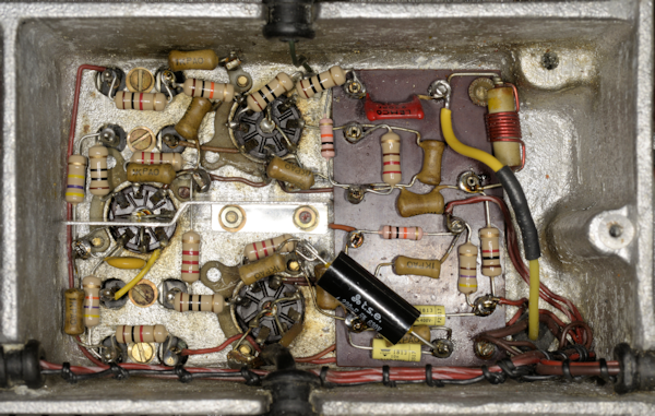
The photograph on the left is the same Harmonic Mixer shown earlier in this article. This time though, it has been fully refurbished and sports a custom-made aluminium screen to replace the one that had been removed. This compartment is actually the heart of what is erroneously called a Wadley Loop. In fact there is no loop. Instead, what happens is this. The Harmonic Generator produces a 'comb' of harmonics from 1MHz upwards. The upper extent is limited by the 30MHz Low-Pass filter. This restricted 'comb' of signals comes into this compartment at the top. The yellow wire on the right is the HT supply to the 1st Local Oscillator and also serves to provide a sample of this signal via the red silvered mica capacitor to the Harmonic Mixer where it is mixed with the 'comb' of harmonics. The two subsequent stages which are tuned to 37.5MHz ensure that there is always an output of 37.5MHz. Thus for every MHz setting, the output of this module is always 37.5MHz. This is effectively the 2nd Local Oscillator, and because it is derived from the 1st Local Oscillator, any drift there is automatically cancelled out. Thus the frequency stability of the RA17 is limited to whatever tiny drift there is in the 2nd VFO (2.1MHz - 3.1MHz).
The output of this compartment is fed to the 37.5MHz filter, which unlike the 40MHz filter, is easy to adjust. But first we need to visit the 2nd Mixer, which technically also involves the 3rd 37.5MHz amplifier.
This compartment mixes the outputs of the 40MHz filter and the 37.5MHz filter. Great care should be exercised when working in here as the trimmer capacitor C108 is technically across the 220V HT line. So it is always a good idea to fully mesh the vanes in case wayward solder-splashes find their way onto the moving vanes. The 1K resistor at the bottom of the photograph will go up in smoke if for any reason C108 is short-circuited. Thus, take care when adjusting C108. TP3, which is at the top right corner of the board is where we hang our oscilloscope probe next. What we're looking for is a healthy 'wad' of signal for every MHz on the MHz dial. I know that sounds vague, but it's not a signal that can be used to trigger the oscilloscope time-base as it's full of noise from the output of the first mixer. This is the characteristic 'chuffing' that RA17 owners talk about.
Set C108 to 50% mesh. With the oscilloscope monitoring TP3, ensure that there is a significant increase in signal for every MHz position. Adjust C7 on the output of the Harmonic Generator so that the level of signal at TP3 at 28MHz and 29MHz are the same. This is not too critical, but the idea is that there should not be a significant drop in receiver sensitivity at 29MHz. Ideally C7 should not be more than 10% meshed.
As previously mentioned, the 2nd VFO and 2nd I.F. are often referred to as the Interpolation Receiver, since it covers the 1000KHz between each MHz. Thus for this procedure, the actual MHz setting is not important, other than it is correctly set (maximum 'chuff').
The 2nd VFO actually tunes 'backwards', i.e. when set to 0KHz, the VFO is at 3.1MHz, and 2.1MHz when set to 1000KHz. The alignment points for this circuit are 100KHz and 800KHz. Thus, if the MHz dial is set to 5, the R.F. input signals will be 5.1MHz and 5.8MHz.
Set the Meter Switch to R.F. Level and adjust C122, C125 and C128 at 5.1MHz, and L57, L58 and L59 at 5.8MHz. Repeat this process until the alignment is correct at both frequencies.
I may be wrong, but I don't think adjustment of these is discussed in the manual. They are however covered in EMER E724 in paragraphs 69 and 70. These form a 'trap' at 2.35MHz, corresponding to 750KHz on the KHz scale. If not aligned, there will be a 'spurious' signal at 750KHz for every MHz setting. If such a response is present, the best way to align these two inductors is to detune them both by unscrewing their cores as far as possible then gradually screw them in simultaneously until the spurious signal disappears.
Connect a signal generator set to provide a CW signal of 50uV to the aerial input.
Set the receiver front panel controls as follows:
RF/IF GAIN ................ mid point
Bandwidth ................ 3KHz
System Switch .......... MAN
AE Attenuator ........... MIN
Tune in the signal using appropriate Preselector settings and adjust the IF/RF Gain and AE Attenuator if necessary, for a reading of mid-scale on the front panel meter. Adjust L50 in the 2nd mixer for maximum meter deflection. Adjust L28 and L33 in the Harmonic Mixer for maximum deflection. The 37.5MHz filter can now be adjusted for maximum deflection. Care should be taken when adjusting the first and last trimmers in this filter since they are at HT potential.
 The 40MHz filter.
Like the 37.5MHz filter, the 40MHz filter is distributed over two boards. The photograph above shows the 40MHz filter of RA17L Ser. N6065. Looking at it, it is very obvious that this has been 'worked on'. One of the 39pF silvered mica capacitors has been replaced with a miniature ceramic type and another has clearly been de-soldered then re-soldered. But it is also obvious that the third trimmer capacitor in the 'chain' (top right) has been tweaked. Something that I have noticed over the years is that one rarely finds trimmer capacitors in RA17s etc. which are barely meshed or fully un-meshed. To my mind, this is a feature of good design, with the lone exception of C7 as previously mentioned. Over time the silver plating on the exposed parts of these trimmers eventually tarnishes. Tweaking one of these will subsequently expose the previously meshed part of the trimmer which has not tarnished, as in the photograph above. Someone has committed the cardinal sin of tweaking the 40MHz filter ... and to what effect? The trimmer on the output of the filter is also fully unmeshed.
 The 40MHz filter (partial) after re-work.
Normally I would have 'reset' these trimmers, using the un-tarnished segments as a guide, but I was curious to see how much this tweaking affected the profile of the filter. It cannot be stressed more strongly that the 40MHz filter is the most critical filter in the entire receiver. This is because this filter sets the input bandwidth of the receiver by limiting the output bandwidth of the 1st mixer to just over 1MHz ... i.e. to cover the 1000KHz on the KHz Film-Scale. Thus, the 'ripple' within the pass-band is actually more important than the insertion loss. The 6dB bandwidth is ideally 40MHz +/- 650KHz and the ripple is ideally no more than 2dB. In today's world, this is what would be referred to as the roofing filter.
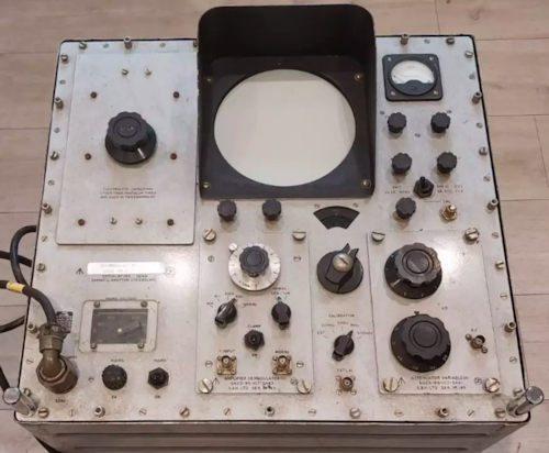
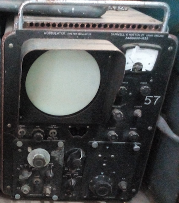
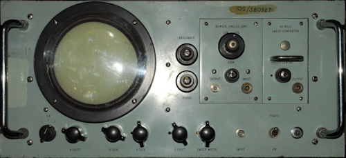
Back in the day, the 40MHz filter was very likely aligned using a Samwell & Hutton CT-501 or Type 78M Wobbulator (above) or maybe even the Racal SA.97 Wobbulator (Left) ... although 10S/5809271 indicates that my SA.97 was from an RAF workshop. All three of these Wobbulators have no calibrated graticule over the CRT, thus requiring them to be calibrated and marked prior to use ... not exactly 'plug and play'.
I currently use my Rigol Spectrum analyser with built-in Tracking Generator when aligning the 40MHz filter. The setup I use is more or less the same as described in A.P.116E-0704-16. V5, V9 and the 1MHz crystal are removed. The output of the Tracking Generator is connected to TP2 and TP3 is connected to the input of the Spectrum Analyser. Both leads use 100nF isolating capacitors. The output level of the Tracking Generator can be set at -10dBm. Obviously, since the 1st mixer is in-circuit, the RA17 needs to be switched on, hence why V5 and the 1MHz crystal are removed ... removing any risk of unwanted responses on the analyser. The covers need to be on the filter, so if the factory-fitted tamper-proof labels are intact, either make the holes yourself or use a set of covers with the holes already present.
Note that although this filter has the same number of elements as the 37.5MHz filter, it is significantly shorter. This is because the 40MHz filter is what is termed 'over-coupled', resulting in every tuned element ultimately influencing all the other elements. Thus, there is no set procedure for aligning it. Therefore it is best left alone. So, why would someone wish to muck up such a critical and difficult to align filter?
There could be any number of reasons, but the most obvious one might be to improve the performance of an ageing receiver. Some people believe that these filters go off with age. They don't, well, not to such an extent that you would see ... that's why silvered mica capacitors are used. As I said in a previous paragraph, the pass-band of the 40MHz filter defines the bandwidth of the RF stage over a 1MHz bandwidth, i.e. that which is covered by the KHz tuning.
Should someone be foolish enough to attempt to tweak the 40MHz filter at a frequency of their choice, they may indeed succeed, or so it would initially appear. The hapless individual would soon realise that although they improved performance at say 14.19MHz, the performance at 14.3MHz might now be considerably worse than before. This is because the filter alignment is required to satisfy several criteria ... >20dB rejection at 40MHz +/- 1.5MHz, no more than 6dB attenuation at 1MHz +/- 650KHz, and a pass-band ripple of no greater than 2dB. One does not simply 'tune' the 40MHz for maximum signal! I decided to see what extent the two maladjusted trimmers had on the grand scheme of things.
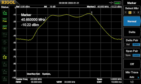

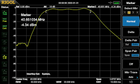
Any adjustment made must be small, starting with the trimmer closest to the 1st Mixer and progressing towards the 2nd Mixer. The image above-left is the response of the filter one I had replaced the ceramic capacitor with a silvered mica one and re-soldered the other one. At this point I have NOT made any adjustments. The response is not bad, but the pass-band ripple is about 6dB. The image above-right is after several iterations of minor adjustments. Note how the insertion-loss is better, but the ripple is still about 6dB.
Finally, I set the third and eighth trimmers to what appeared to be the factory settings ... using the un-tarnished sections of the trimmers as a guide. I then went back over all eight trimmers and obtained the image on the left. Bingo! Note how the pass-band ripple is significantly lower and the rejection at 40MHz +/- 1.5MHz is greatly increased. This is what the profile of the 40MHz filter should look like.
The only thing to do now is the final sensitivity test ...
18dB s+n/n with BANDWIDTH set to 3KHz for 1uV CW, and for 3uV AM at 30% modulation at 1KHz.
Although I have an HP8920A Transceiver Test Set, I am more comfortable using my Adret 740A signal generator and Marconi 893B Audio Power Meter for this test.
The procedure is as per the manual. Set the receiver controls as follows ...
AE ATTENUATOR to MIN
I.F. GAIN to MAX
A.F. GAIN to MAX
BANDWIDTH to 3KHz
AE RANGE, MC/S and KC/S to appropriate setting
METER switch to R.F. LEVEL
System switch to MAN
Connect the input of the AF power meter to the '50mW' terminals at the rear of the receiver and set the impedance of the AF power meter to 3 ohms. Leave the SPEAKER switch set to ON for the moment. I find this helpful. Set the signal generator for 1uV CW. Tune in the signal for maximum deflection on the meter. Now set the meter switch to A.F LEVEL and switch on the BFO. The RA17 and RA17L use RF Pentodes as audio amplifiers which is not ideal. I find that it is not difficult to over drive them at this point, so with the BFO on I back off the A.F. GAIN control to a point where the tone is clear. Adjust the BFO for maximum deflection on the meter and if necessary back off the A.F. GAIN if distortion returns. Now switch off the Speaker on the front panel. Using the I.F. GAIN control reduce the gain such that the power meter reads 100mW. This is your reference. Now switch off or remove the RF signal and measure the new reading on the power meter. It should read at least 18dB less than the reference. Do this at 1.6MHz, 14.6MHz and 28.6MHz. There is nothing special about these frequencies other than I have found them to be free from strong external signals.
The test for AM sensitivity is slightly different. Set the receiver controls as before. Set the signal generator for 3uV with 30% Amplitude Modulation. Leave the meter switch to R.F LEVEL. The BFO should be OFF and SPEAKER switch initially set to ON. Tune in the signal and make any necessary changes to the A.F. GAIN setting such that the distortion in the speaker is at a minimum as before. Switch off the loudspeaker and using the I.F. GAIN control reduce the gain such that the power meter reads 100mW. I find it helpful at this point to re-tune the receiver to maximize the deflection on the power meter. Re-ajust the I.F.GAIN for 100mW on the power meter. As before, this is your reference. Now switch OFF the modulation and measure the level on the power meter. It should be at least 18dB less than the reference. Do this at 1.6MHz, 14.6MHz and 28.6MHz as before.
RA17L Serial N6065 out-performed Racal's specification thus ...
Note: I have experimented with different settings for the I.F and A.F Gain controls for setting the output level to 100mW and find that it makes little difference to the final result.
Since I replace ALL the carbon resistors with 1W (or 800mW) carbon-film or metal-film ones, both types being lower noise than the old-fashioned composite types, the overall nose figure is naturally reduced. The original paper capacitors tended to morph into resistors over time, with heat being a catalyst. The more d.c. a capacitor passed, the more heat was produced and thus more leakage. Hence the term 'leaky' capacitors. The most vulnerable capacitors are those across the HT line or decoupling screen supplies where they are usually in parallel with the bottom resistor in a potential divider. In this case the d.c. resistance of the leaky capacitor, being across the bottom resistor, causes the screen voltage to rise, the resistance continues to rise across the capacitor and it degrades further, resulting in a runaway failure where the top resistor in the potential divider heats up to a point that it burns out, but not before the poor valve suffers terminal damage.
As these capacitors are failing, they generate noise as a result of the wax impregnated tissue paper dielectric breaking down ... thus another source of noise. And for this reason I replace ALL tubular paper capacitors, AND the smoothing pack. The latter is replaced with aluminium electrolytics and the former are replaced with polypropylene types. Polypropylene is inert compared to wax impregnated paper.
Another source of noise is obviously the valves themselves. Poor heater-cathode insulation is the most common cause, although other inter-electrode shorts can occur. For some reason EF93s appear to be the most susceptible to this type of failure. Failure of vacuum, or compromised vacuum can also result in noise. Interestingly, in over sixty receivers and ancillary items (ISB adapters etc.), the only valves that I have encountered where the gettering has turned white, indicating vacuum failure, have been E180Fs. These are the only valves in the RA17 with gold-plated pins. These valves run extremely hot and it is my theory that since gold is both soft and porous, that over time the seal around the pins fails at a microscopic level, allowing molecules of gasses present in the air to be drawn into the glass envelope. I was discussing this with one of my clients when he confirmed my theory. When working for Marconi, he too had witnessed this failure in E180Fs and managed to link the failure to the gold-plated pins.
I am very fortunate to have an AVO VCM-163 Valve Characteristic Meter on which I test all the valves. Interestingly, I have noticed that many of the last EF91s (CV4014) that Mullard produced in the 1980s, do not perform as well as earlier ones. This too, was confirmed by my client.
I frequently receive emails from RA17 owners who are either themselves refurbishing one or are in the process of repairing one. Often they are simply writing to acknowledge what I do and to let me know that my articles have inspired them, while others might be seeking help with a tricky problem. Either way I appreciate these emails and it is most gratifying to read how much my efforts have inspired and helped so many RA17 enthusiast.
My initial encounter with an RA17 left me very unimpressed. The owner had been most enthusiastic, describing it as a 'classic' and that the performance was 'legendary'. To me, it was noisy, deaf, and smelly. As I was short of space at the time, I politely handed it back. Years later when I 'inherited' it, I had been inspired by Peter Holtham's (now deleted) blog on his RA117 total strip-down and re-build. That was back in 2009, and I've been refurbishing RA17s and the like ever since. Like Peter, I replace all the carbon-composite resistors and all the tubular paper capacitors. Some will think this unnecessary, but after sixty RA17s through the workshop, I can confirm that the effort is definitely worth it ... and, I can remove and replace these components quicker than it takes to isolate and test them.
So, I thought it might be a good idea to write an article on how I go about aligning these receivers and why my method differs from that in the manual. Also, I will endeavour to highlight as many of the possible issues that one could expect to encounter whilst bringing an RA17 back to life.
We start with a close examination of the receiver ...
Not an RA17L front panel.
Wrong knobs.
It isn't unusual to find the occasional knob in the wrong place, but in this case no less than seven of the knobs on the front panel were actually wrong. Six of these looked like they might have come from a piece of Marconi test equipment.
The front panel was in terrible condition, with several square centimetres of paint chipped off and several deep ugly scratches. It was questionable if the handles were genuine as both had been painted silver, the 'shoulders' were missing and it turned out that the threads for the screws were metric, not BA threads. I was told it was an RA17L, but straight away I could tell that the front panel was from an RA17, a MK2, if the serial number on the front had any bearing.
Three of the toggle switches didn't look right. The mains switch was not original and the nuts retaining the Speaker and Meter switches were grey plastic! The Ernest Turner meter had been replaced with a modern square type.
And, I was still yet to take the covers off ...
Often an RA17 turns up without a top cover, and occasionally the bottom cover can be missing. This one came with both covers, so that was a plus. Once these were removed, I noticed that a previous owner had replaced ALL the Hunts tubular capacitors, with one or two exceptions. Also, it was clear to my 'experienced eye' that many of the screws holding the receiver together were wrong. Most noticeable was the use of cross-head, or Phillips screws on the individual compartment covers, some of which were very bright, which made me think that they might be M3 ... and an M3 screw will not go into a 6BA thread without considerable persuasion. The serial plate confirmed that his was indeed an RA17L with Serial Number N6065 and the year of manufacture was given as TB, which is February of 1962
As well as the front panel being from a MK2, distinguishable by the range of Filter Bandwidths and BFO scale, I also noticed that the shaft on the BFO control was NOT a reduction drive ... so was the 100KHz IF strip the correct type?
Something worth mentioning here is that almost all removeable assemblies in the RA17 (and RA17L etc.) will have a serial number written on them somewhere. This includes the Crystal and LC filter modules, the two VFOs and even the small 'rear panel' on which the serial plate is attached. These serial numbers will not necessarily match that on the serial plate, but they do serve to indicate if a sub-assembly has been replaced, if for instance there is a marked difference.
In this case, the 100KHz IF strip was marked 6219, thus likely original, and the crystal and LC modules were marked 6918 and 6919 respectively. Lifting the lid off the crystal filter revealed four crystals, confirming the 300Hz and 100Hz bandwidths for an RA17L. MK1 and MK2 RA17s have three crystal filters and thus this module would then have six crystals fitted. A quick look at the top of the BFO module revealed a serial number of 780 ... definitely removed from an RA17 MK2 ... why?
It always amazes me, the ignorance (and I don't mean that disrespectfully) that some RA17 owners exhibit regards the differences between the RA17 and the RA17L. RA17s can be classed as MK1s, which might include all early production models up to serial 510, although the jury is still out on that. MK2s are all the others up until the introduction of the RA17L which can be considered a MK3. All variations thereafter are still MK3s with the exception of the RA17N from which the RA117 was developed ... more on that later.
For now, here is a list of external differences relating to the RA17 and RA17L ...
Early Bat-Wing knobs.
Early MK1 receivers will have the early 'bat wing' knobs on the rotary switches and BFO (see left). Note that the BFO range is +/- 3KHz with no reduction drive.
RA17Ls and thereafter will have the later style of knobs (see right). Note that the BFO range is +/- 8KHz and that the knob is a two-part affair incorporating a reduction drive.
MK2 receivers will look very similar to MK3s with the exception that the BFO range and filter bandwidths will be like that on the MK1. The BFO knob might be different. I have seen some where the knob is the same as the filter B/W switch, and others where the knob has the same profile as that on the MK3 but without the moving disc.
Note the difference in filter bandwidths between the RA17L (right) and those that preceded it (left). A quick check is to look for the widest bandwidth, where 8KHz is a good indicator of a MK1 or MK2 and 13KHz indicates an RA17L etc. Other filter bandwidth combinations are available ... but far too many to list.
Later Knobs.
Very Early RA17, Ser. N54
Very early RA17s might have knurled tuning knobs, like the one in the photograph on the right.
The only other external differentiating feature can be found on the serial plate at the rear. MK1s will be labelled RA17, MK2s will be labelled RA17 MK2 and all the rest will be labelled as RA17L, RA17W etc.
Back to RA17L N6065 ...
As I said, a previous owner had judiciously removed almost all the 'Hunts Horrors' capacitors and replaced them with modern types ... although I think that might have taken place thirty years ago. However, rather than replacing old axial capacitors with modern axial types, they had fitted radial types ... functional, but not so neat. Also, it was clear that most of the 50nF capacitors had been replaced with 68nF capacitors. Since 47nF capacitors are the modern replacement for 50nF and are readily available, I believe that perhaps an abundance of 68nF capacitors had been at hand. The difference in performance would have been nil, but I prefer to keep all replacement components as close as possible to the original.
Several of the original carbon resistors had also been replaced. These were likely ones that had shown external signs of stress. Some had been replaced with wrong values and this I found worrying. There are three possible reasons why a 'wrong' value might be fitted. Perhaps the owner didn't have the correct value at hand so simply fitted the next resistance value in the series ... not likely to cause big problems, but also not really a good idea. Another reason might be that the original resistor was so badly cooked that the colour bands were mis-read. I've done that at least once. The third reason, and I've seen this on a couple of occasions is where Racal had fitted two 1K resistors in parallel to spread the power dissipation, and someone has then fitted a suitable 470 ohm resistor in their place. Yes it works with zero change in performance, but the moment you replace a parallel pair with a single resistor, the physical circuit then differs from the schematic. Always replace parallel pairs with parallel pairs, it avoids confusion.
New components are easy to spot, and I couldn't help noticing that the two 10 megohm resistors in series, connected between the AGC line at V3 (EA76) Anode and the +220V rail, had been replaced with two 1 megohm resistors. Why would anyone do that? Firstly, these resistors are in a very stress-free part of the circuit. Even if for some reason C159A or C159B had gone short-circuit, the resulting power dissipation in each resistor would only be in the region of 2.4mW. So why replace them? I will probably never know.
What purpose do these two 10 megohm resistors serve? Curiously, Racal's description of the AGC (AVC) circuit in the RA17L manual is identical to that in the RA17 manual. i.e. they never bothered to update Part 1, Section 5 of the manual, the Detailed Circuit Description, to reflect the updated AGC circuitry in the RA17L. However, I remembered reading an excellent description of the latter but couldn't remember where I'd found it ... until I found my own notes referring to the same circuit in the RA17W, which I apparently found in a discussion on the UK Vintage Radio Repair and Restoration forum. Here is the essence of that explanation ...
In the original RA17, V24 (or MR8) does not appear: AGC is applied to the 1st IF amp. (V14), 2nd IF amp. (V16) and IF O/P (V17) only. There is no AGC voltage applied to the RF amp. (V3, E180F) at all. Consequentially the RF amp. could easily be overloaded - especially when the receiver is operated in close proximity to an associated transmitter.
The RA17L (and RA17W) which uses a cascode RF amp (ECC189) - however does have AGC applied to this stage - which, of course, circumvents this overload problem. However, to optimise the S/N ratio, the AGC voltage on this RF amp. is only required to 'come on' for large signals. Hence, by biassing the AGC line to the RF amp. slightly positive - by the action of V24 and the two 10M-ohm resistors, which are connected to HT+, the -ve AGC line will have to become significantly large to overcome this +ve bias. That is, it will only go -ve for really strong signals, so the RF amp. becomes the last stage to have its gain reduced under these conditions. Note that R91A (470K) substantially reduces the possibility of this +ve bias upsetting the -ve AGC voltage that is applied to the 100Kc/s 1st IF amplifier. In the RA17L, this is the ONLY IF stage to which AGC is applied.
Thus, the two 10 megohm resistors form part of a potential divider which ensures that the AGC to the RF amplifier stage is held slightly positive until the actual AGC line becomes negative enough to overcome it. Therefore replacing these two resistors with two 1 megohm resistors changes the characteristic of the potential divider resulting in an even higher +ve bias. It is highly likely that this mistake meant that the gain of the RF amplifier was never affected by the AGC. When I refurbished the 100KHz module, I fitted two 10 megohm resistors.
These days when I take on an RA17 refurbishment job, I don't bother switching on the receiver to see if it works. The first thing I do is strip it down to its individual assemblies. This involves removing the front panel and the two side panels. Everything that is removed is then carefully stored in a series of boxes and any fixings (screws etc.) are stored in a separate partitioned box with individual compartments allocated to different assemblies. This way I can ensure that what comes out, goes back in (as long as it is correct!). This was when I realised that RA17L Ser. N6065 had clearly been stripped down and then reassembled ... but not before many of the associated fixings had been lost. The front and side panels are normally secured using counter-sunk screws. Half of the front panel screws were not the originals and about half of those securing the side panels were NOT counter-sunk.
When I removed the two VFO modules, I found that in both cases the bottom cover was missing, which implied that at least 15 6BA screws were missing ... and not only that, one of the long 2BA screws that secures the 2nd VFO to the chassis was missing. Two of the 4BA screws securing the 100KHz module were missing ... and the top cover over L70 and L75 on the calibrator was missing. I suspect that this RA17L lay in pieces for quite some time! ... long enough to loose bits of it.
There was no 56K resistor in series with the AGC at the connection to the 1st VFO module, nor was there the associated ceramic stand-off. The addition of this resistor is the subject of Modification Instruction 11, issued in September of 1965. The fact that Mod 11 is not struck through on the Mod Strike Label at the rear may suggest that this receiver 'slipped though the net' to the extent that this mod was never carried out.
Missing screen.
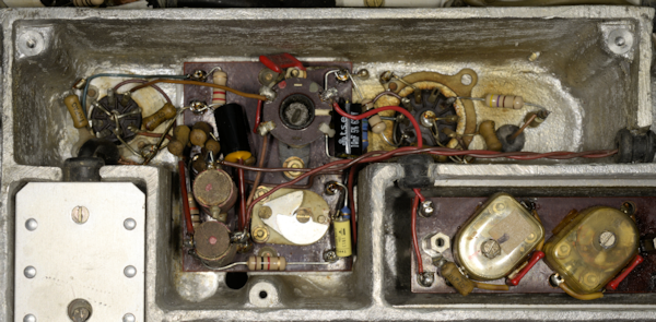
Up to this point, the only other major issue that I discovered was that the aluminium screen which divides the Harmonic Mixer/37MHz Amplifier compartment was missing; as can be seen in the photograph on the left. Also in this compartment, the orange wire connecting V4 pin 4 and V6 pin 3 is confusing, since in these receivers, orange is traditionally associated with Screen Grid circuits. This should be a brown wire as it is part of the heater circuit.
It is probably worth pointing out here that the heater wiring for V6 is not as per the schematic since pins 3 and 4 are swapped. This is the case for ALL RA17s.
At risk of sounding pedantic, the yellow wire from V6 pin 5 is the wrong type of wire and the wrong gauge so likely not original. The capacitor decoupling V6 pin 7 to ground is the correct value (1nF) but should be ceramic. The big yellow capacitor at the bottom is 0.5uF and connected across the heater supply in this compartment. For authenticity's sake, this should be 0.22uF.
It is worth saying here that taking an RA17 or any of its variants apart is a tedious affair. The side panels are easy enough, but to remove the front panel, ALL the knobs must first be removed. Thereafter, the wires to the meter must be disconnected, and probably also remove the meter toggle-switch from the panel since the wires are just that little bit too short for comfort. You could also remove the Speaker-switch at this point but it is just as easy to de-solder the two wires from the centre pins. Only then can the panel be put aside. For some reason, the rear of the front panel of this receiver had been painted a metallic grey colour ... never seen that before.
Frustratingly, the 1st VFO module cannot be removed from the chassis unless the 2nd VFO module is first removed ... and neither can be removed until the Calibrator is removed first. Fortunately this is the easy bit. Removing the 2nd VFO is not so easy. The first thing to do is turn the chassis upside-down and remove the covers from the 40MHz filter. There will be a red wire and an orange wire from the 1st VFO going to one end of the filter. Convention dictates that the red wire should go to the tag closest to the front of the receiver. Next, remove the yellow wire from the 1st VFO where it connects to the junction of L20 and C42 adjacent to the Harmonic mixer (V4).
Disconnect the HT and Heater wiring from both VFOs and remove the coax from the Aerial Attenuator that feeds up through the chassis to the RF amplifier. Now you can disconnect the three coaxes to the 2nd VFO module. The plastic MHz disc must be removed before the 2nd VFO can be removed (See the photograph below). This is more fragile than it looks. Why on earth had someone found it necessary to do that to get the four 6BA C/SK screws out?
Both VFO modules in the RA17L are secured by three 2BA screws. On the 1st VFO they are obvious ... but not so the 2nd VFO. One is at the rear left corner. A second shorter screw can be found at the front left corner where it goes through a small lug. This screw does NOT feature in MK1 receivers. The third is hidden inside the module itself, and to gain access to it, the top cover of the module must be removed ... requiring the removal of no less than sixteen 6BA CH/HD screws! After which, the last 2BA screw will be found front-right. Withdraw all three screws and carefully lift the module up then slide it forward. This is why the MHz disc must first be removed. Now you can do the same to remove the 1st VO module. In this case, the 1st VFO module was not a pretty sight (see the photograph below). Most of the screws securing the Pre-Selector tuning capacitor cover were missing and there was a heavy rust residue from the Meccano chain and gears encrusted on the front aluminium plate.
Not a pretty sight.
MHz disc.
Alignment procedure
This assumes that all tubular paper capacitors have been replaced with modern aluminium or polypropylene types and that all carbon-composite resistors have been replaced with carbon-film or metal-film types. I use 1W types up to 1M then 0.5W up to 10M.1st VFO module
VFO1 Test Jig.
Although Part 2, Section 5 of the User Manual does provide an alignment procedure, I prefer to refer to EMER E724 when aligning RA17s etc. This document can be obtained from the manuals section of The Wireless-Set-No19 Group.
Bear in mind that when these procedures were written, test equipment was somewhat less sophisticated than what many of us have at our disposal today. Oscilloscopes with a bandwidth in excess of 10MHz were few and far between. Thus a lot of measurements call for an (rms) Valve Voltmeter, but there is no mention of input impedance. I have a Marconi TF.1041B which would be appropriate, with an input impedance of greater than 5 Megohms.
I've also got a Racal-Dana 9301A true rms Voltmeter ... a superb bit of kit, BUT unfortunately the input impedance is 50 ohms, so not appropriate in this case. However, these days, an oscilloscope with a Y-bandwidth of 100MHz is considered quite modest. Thus, when the procedure refers to a reading on the 'valve voltmeter' it is just a case of taking the peak-to-peak reading from the oscilloscope and multiplying it by the reciprocal of 2 x root 2 (or 0.353). Using an oscilloscope also has another benefit ... you can instantly see the shape of the waveform, which can often alert you to distortion or noise issues.
When aligning the 1st VFO module, I start with the Pre-Selector. This part of the procedure actually tests the RF amplifier as well as the Pre-Selector. My signal generator (Adret 740A, or 7100D) is obviously connected to the RF input, whilst my oscilloscope (Tektronix 7603 with 7A26 Y-plug-in) is connected to TP2. I will be honest, I don't actually pay too much attention to the voltage swing at TP2, other than to verify that there is appropriate gain. I find that if the output from the RF amplifier is in the right 'ball park' for the prescribed input level, then all is well.
If you find that there is no signal at TP2, check the continuity of the Low-Pass filter. I know of two occasions where one of the series inductors has failed open circuit for no obvious reason. My theory is that both these failures were the result of too much tension where the thin enamelled copper wire is wound round one of the sixteen pins along the length of Tufnol tube during manufacture.
RA17L VFO1 Schematic
Note that the preselctor in the RA17L comprises six double-tuned transformers, each of which contains two ferrite cores. Both windings are resonated by a separate ganged variable capacitor and a tubular trimmer capacitor on each primary winding provides fine adjustment at the high end of each range. The alignment procedure calls for the low end of each range to be set first, yet Racal do not suggest an initial setting for the individual trimmer capacitors. When aligning each of these at the low frequency end, it is important to remove the top core first. This will reduce the output at TP2, so the sensitivity of the oscilloscope will need to be increased to about 10mV/div. Then adjust the bottom core for a peak in amplitude. This will be small and will be found when the core is close to the bottom of the former. There is no risk of screwing the bottom core so far that it falls inside the module, but you will need a long non-metallic tool. Then re-fit the top core and adjust for maximum amplitude again. The cores should NOT touch. On each range, the single tubular trimmer capacitor is then used to peak the response at the top end of the range. Obviously the inductance and capacitance settings are co-dependant. Thus the final setting for the trimer capacitors will depend on the transformer cores and vice-versa. If you find that the capacitor is either too far "out" or fully "in" and still not providing a discernible peak, then it might be necessary to set it mid-travel at the high end then re-adjust the transformer at the bottom end.
RA17 VFO1 Schematic
The preselector in the MK1 and MK2 RA17 is significantly simpler than the RA17L. Each of the six bands is covered by a single-tuned tapped inductor resonated by a single variable capacitor. Alignment is carried out at a single frequency on each range ... and this time it is possible to screw the core so far that it can fall inside the module. This is why we align the preselector on the bench, not on the chassis. The other obvious difference between the RA17L and the RA17 is that the latter employs a pentode as the RF amplifier whilst the former employs a cascode-configured double triode.
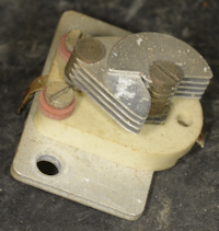
C77.
Next we come to the VFO. As part of the refurbishment process, there are two things that I always do with respect the VFO. One is to remove and clean the small trimmer capacitor C77 (30pF). This little capacitor is used for setting the high frequency end of the VFO and is accessible through a hole in the top of the module. Inevitably dust and other contaminants, depending on the environment, can find their way into the space between the vanes and seriously change the value of capacitance. I once had one which measured more than 100nF! Consequently the VFO will not run, and if you find this out while both VFOs are on the chassis, you will need to remove the 2nd VFO before you can remove the 1st VFO in order to clean the capacitor. I learned this the hard way. The second thing I do is ensure good contact between the rotor of C76 and the chassis, as any form of contact uncertainty can result in noise when tuning or in some cases cause the VFO to stop oscillating. Eliminate the likelihood of these issues before screwing the lid back on the module.
Caution!: It is imperative that before aligning the VFO, verify that when the MHz disc is fully counter-clock-wise, the 'zero' calibration mark which is the vertical line to the right of the figure zero, is in line with the MHz cursor. This should also coincide with C76 being not quite fully meshed. If not, the hub that the disc attaches to will need to be rotated. This requires that two 0.005" Allen screws be slackened off. Heat may need to be applied in order to 'unlock' these. DO NOT apply heat when the disc is in place. Also be aware that the markings on the disc are very likely water-soluble ... crazy!
In the past, measuring the frequency of the 1st VFO (40.5MHz to 69.5MHz) could be a tricky affair, as attaching any test equipment to the output of the VFO inevitably led to the frequency being 'pulled'. The original procedure called for a wire loop to be placed around the valve (V5), then connected to a frequency counter. I always found this method tricky as even then, the frequency was still influenced by the test equipment, making calibration of the MHz VFO fraught with uncertainty. However I recently found that my very affordable Tiny SA Ultra is probably the best tool around for this purpose. I simply set it to scan 40MHz to 70MHz, fit the telescopic antenna to the input and set it in the vicinity of the VFO. There is no need to enable to LNA either. The display will show the VFO signal and can be set to identify the frequency. This way I can calibrate the VFO in minutes and have the confidence that no further adjustment will be required.
Finally we have the 1st Mixer. No alignment here ... it either works or it doesn't ... and in sixty RA17s, I've yet to find a fault here that wasn't a duff E180F ... and since I test every valve before I get to this stage, it always works. As with the VFO, something like the TinySA will make your life so much easier. The 1st mixer is an up-converter i.e. the 1st IF is higher than the input. In this case, the IF is 40MHz. So you need to set the spectrum analyser to sweep either side of 40MHz. Set the sweep to something like 1MHz. Choose a MHz, i.e. set the MHz dial to 5 and then apply a 5MHz signal of about 30mV emf to the module RF input. This should result in an output at 40MHz on the spectrum analyser. This can be verified at frequencies across the range of 1MHz to 29MHz.
Finally, and this might be amusing. The second RA17 that I refurbished was a MK1 RA17. Thus the RF amplifier in the module was based around an E180F or CV3998. When I opened it up, R28 (680R) was toast. I mentioned this to the owner (a good friend of mine) and he laughed. According to him, the person from whom he got it had made a rather uninformed and ultimately unwise decision ... based on the fact that RA17Ls were 'better' than RA17s ... and since RA17Ls used ECC189s in the RF amplifier, replacing the E180F with an ECC189 would improve the performance ... hmmm? ... moving on ...
2nd VFO module
VFO2 Test-Jig.
On it's own it does not provide a way of verifying the operation of the mixer stage. Testing what is the 3rd mixer in the RA17, requires another in-house test-jig used for testing the 100KHz IF strip, and a working IF strip. Since testing the latter is a simple matter when it is part of the receiver, I choose to forego testing the 3rd mixer on its own. Like the 1st Mixer, the 3rd Mixer is so simple that I have yet to encounter one that didn't work.
The tuning mechanism of the VFO employs a factory-sealed inductor ... i.e. the inductance cannot be varied. The variable capacitor which tunes the oscillator is third from the front of the 4-gang capacitor assembly. The other three ganged variable capacitors are configured as a tuneable band-pass filter between the 2nd and 3rd mixer stages. Thus at this stage in the alignment process, the only adjustments that need to be made are to set the VFO frequency by way of the trimmer capacitor C136 or to physically move the film scale.
At this stage, I refurbish several under-chassis parts which would otherwise be difficult or even impossible to access whilst their retaining screws are obscured by one or other of the two VFOs. These parts are the Aerial Attenuator, the Meter Rectifier and the two resistors on the end of the 30MHz Low-Pass filter which follows the Harmonic Generator. Only then do I re-fit the two VFOs and remove the 100KHz IF strip in order to refurbish it.
The 3rd, or 100KHz I.F. module
Typical RA17 IF module.
In terms of component count, the 100KHz IF strip is the largest single removable assembly in the RA17. It comprises a two-stage IF amplifier, an IF buffer stage for driving external side-band adapters, an AGC generator and distribution circuit, two filter modules and the BFO.
Typical RA17L IF module, underside.
With reference to the photograph above, the tag-boards are, from left to right, AGC and Detector, two-stage IF Amplifier, AGC Distribution, and finally the IF output Buffer stage.
As you can see, there are no less than twenty tubular capacitors, originally by Hunts, which get replaced when I do a refurbishment. Statistically this assembly yields the worst-case out of spec. resistors, especially from the IF amplifier stages, where the resistors are frequently so badly cooked that I can't read the colour bands. 'Leaky' decoupling capacitors are invariably the cause.
The BFO can be tested on the bench. Do not be alarmed that the waveform is so clipped that it is almost a square-wave. The 100KHz IF strip will be aligned as part of the fully assembled receiver ... so now is the time re-fit it and the front panel, in that order.
The procedure in the manual for aligning the IF amplifiers is excellent from a diagnostics point of view, but I admit that I haven't had need to use that method for some time. Instead I have adapted that procedure to involve my Rigol Spectrum Analyser and Tracking Generator. V12 is removed and a connector is inserted into the socket to allow the output of the tracking generator to be connected to pin 5 via a 100nF isolating capacitor. The input to the analyser is connected to the junction of C193 (100pF) and V18 pin 7, again using a 100nF isolating capacitor. Initially I configure the the analyser and tracking generator to operate over a range of 80KHz to 120KHz, and find that the output of the tracking generator can be kept at -10dBm. The sweep width can then be adjusted pro rata with respect to the filter under test. This setup enables me to adjust the gain and bandwidth of the two IF amplifiers, the LC filters and the crystal filters in real-time without the need to connect the damping resistors. I also remove the 1MHz crystal as a precaution, just to keep any unwanted signals to a minimum.
1MHz Oscillator, Harmonic Generator, Harmonic Mixer, 37.5MHz Amplifiers and the 2nd Mixer
Once again, this assumes that all of these areas have been cleared of 50s or 60s paper capacitors and carbon resistors. The Oscillator either works or it doesn't. If the output is low, replace the 4.7nF capacitor. I replace this as a matter of course as I find that it more often than not degrades upwards in value, and thus attenuates the input to the Harmonic Generator. Adjust L2 for maximum signal at the pair of Pye Pattern 12 connectors. Adjust C2 to set the frequency to exactly 1MHz. Ensure that C7 in the anode circuit of the Harmonic Generator is only slightly meshed. This is located on top of the 30MHz Low-Pass filter adjacent to the Harmonic mixer. There is no point in trying to measure the level of output from the Harmonic Generator.
Harmonic Mixer and first two 37.5MHz amplifiers.
The photograph on the left is the same Harmonic Mixer shown earlier in this article. This time though, it has been fully refurbished and sports a custom-made aluminium screen to replace the one that had been removed. This compartment is actually the heart of what is erroneously called a Wadley Loop. In fact there is no loop. Instead, what happens is this. The Harmonic Generator produces a 'comb' of harmonics from 1MHz upwards. The upper extent is limited by the 30MHz Low-Pass filter. This restricted 'comb' of signals comes into this compartment at the top. The yellow wire on the right is the HT supply to the 1st Local Oscillator and also serves to provide a sample of this signal via the red silvered mica capacitor to the Harmonic Mixer where it is mixed with the 'comb' of harmonics. The two subsequent stages which are tuned to 37.5MHz ensure that there is always an output of 37.5MHz. Thus for every MHz setting, the output of this module is always 37.5MHz. This is effectively the 2nd Local Oscillator, and because it is derived from the 1st Local Oscillator, any drift there is automatically cancelled out. Thus the frequency stability of the RA17 is limited to whatever tiny drift there is in the 2nd VFO (2.1MHz - 3.1MHz).
The output of this compartment is fed to the 37.5MHz filter, which unlike the 40MHz filter, is easy to adjust. But first we need to visit the 2nd Mixer, which technically also involves the 3rd 37.5MHz amplifier.
2nd Mixer and third 37.5MHz amplifier.
This compartment mixes the outputs of the 40MHz filter and the 37.5MHz filter. Great care should be exercised when working in here as the trimmer capacitor C108 is technically across the 220V HT line. So it is always a good idea to fully mesh the vanes in case wayward solder-splashes find their way onto the moving vanes. The 1K resistor at the bottom of the photograph will go up in smoke if for any reason C108 is short-circuited. Thus, take care when adjusting C108. TP3, which is at the top right corner of the board is where we hang our oscilloscope probe next. What we're looking for is a healthy 'wad' of signal for every MHz on the MHz dial. I know that sounds vague, but it's not a signal that can be used to trigger the oscilloscope time-base as it's full of noise from the output of the first mixer. This is the characteristic 'chuffing' that RA17 owners talk about.
Set C108 to 50% mesh. With the oscilloscope monitoring TP3, ensure that there is a significant increase in signal for every MHz position. Adjust C7 on the output of the Harmonic Generator so that the level of signal at TP3 at 28MHz and 29MHz are the same. This is not too critical, but the idea is that there should not be a significant drop in receiver sensitivity at 29MHz. Ideally C7 should not be more than 10% meshed.
2nd I.F. Alignment
The procedure in the manual calls for a signal to be injected at TP3. This is probably only necessary when fault-finding. As we have already refurbished, tested and aligned every stage prior to and after, all we need to do is apply a suitable R.F. signal at the Aerial Connector.As previously mentioned, the 2nd VFO and 2nd I.F. are often referred to as the Interpolation Receiver, since it covers the 1000KHz between each MHz. Thus for this procedure, the actual MHz setting is not important, other than it is correctly set (maximum 'chuff').
The 2nd VFO actually tunes 'backwards', i.e. when set to 0KHz, the VFO is at 3.1MHz, and 2.1MHz when set to 1000KHz. The alignment points for this circuit are 100KHz and 800KHz. Thus, if the MHz dial is set to 5, the R.F. input signals will be 5.1MHz and 5.8MHz.
Set the Meter Switch to R.F. Level and adjust C122, C125 and C128 at 5.1MHz, and L57, L58 and L59 at 5.8MHz. Repeat this process until the alignment is correct at both frequencies.
Inductors L51 and L52
These are the two cans, one shorter than the other, immediately behind the 2nd VFO module.I may be wrong, but I don't think adjustment of these is discussed in the manual. They are however covered in EMER E724 in paragraphs 69 and 70. These form a 'trap' at 2.35MHz, corresponding to 750KHz on the KHz scale. If not aligned, there will be a 'spurious' signal at 750KHz for every MHz setting. If such a response is present, the best way to align these two inductors is to detune them both by unscrewing their cores as far as possible then gradually screw them in simultaneously until the spurious signal disappears.
The 37.5MHz Filter
Unlike the 40MHz filter, the 37.5MHz filter can be aligned simply by tuning to a steady signal (ideally from a signal generator) and 'peaking' each trimmer for a maximum reading on the front panel meter.Connect a signal generator set to provide a CW signal of 50uV to the aerial input.
Set the receiver front panel controls as follows:
RF/IF GAIN ................ mid point
Bandwidth ................ 3KHz
System Switch .......... MAN
AE Attenuator ........... MIN
Tune in the signal using appropriate Preselector settings and adjust the IF/RF Gain and AE Attenuator if necessary, for a reading of mid-scale on the front panel meter. Adjust L50 in the 2nd mixer for maximum meter deflection. Adjust L28 and L33 in the Harmonic Mixer for maximum deflection. The 37.5MHz filter can now be adjusted for maximum deflection. Care should be taken when adjusting the first and last trimmers in this filter since they are at HT potential.
The 'infamous' 40MHz Filter
The 40MHz filter.
Like the 37.5MHz filter, the 40MHz filter is distributed over two boards. The photograph above shows the 40MHz filter of RA17L Ser. N6065. Looking at it, it is very obvious that this has been 'worked on'. One of the 39pF silvered mica capacitors has been replaced with a miniature ceramic type and another has clearly been de-soldered then re-soldered. But it is also obvious that the third trimmer capacitor in the 'chain' (top right) has been tweaked. Something that I have noticed over the years is that one rarely finds trimmer capacitors in RA17s etc. which are barely meshed or fully un-meshed. To my mind, this is a feature of good design, with the lone exception of C7 as previously mentioned. Over time the silver plating on the exposed parts of these trimmers eventually tarnishes. Tweaking one of these will subsequently expose the previously meshed part of the trimmer which has not tarnished, as in the photograph above. Someone has committed the cardinal sin of tweaking the 40MHz filter ... and to what effect? The trimmer on the output of the filter is also fully unmeshed.
The 40MHz filter (partial) after re-work.
Normally I would have 'reset' these trimmers, using the un-tarnished segments as a guide, but I was curious to see how much this tweaking affected the profile of the filter. It cannot be stressed more strongly that the 40MHz filter is the most critical filter in the entire receiver. This is because this filter sets the input bandwidth of the receiver by limiting the output bandwidth of the 1st mixer to just over 1MHz ... i.e. to cover the 1000KHz on the KHz Film-Scale. Thus, the 'ripple' within the pass-band is actually more important than the insertion loss. The 6dB bandwidth is ideally 40MHz +/- 650KHz and the ripple is ideally no more than 2dB. In today's world, this is what would be referred to as the roofing filter.
CT-501 Wobbulator.
Type 78M Wobbulator.
Racal SA.97 Wobbulator.
Back in the day, the 40MHz filter was very likely aligned using a Samwell & Hutton CT-501 or Type 78M Wobbulator (above) or maybe even the Racal SA.97 Wobbulator (Left) ... although 10S/5809271 indicates that my SA.97 was from an RAF workshop. All three of these Wobbulators have no calibrated graticule over the CRT, thus requiring them to be calibrated and marked prior to use ... not exactly 'plug and play'.
I currently use my Rigol Spectrum analyser with built-in Tracking Generator when aligning the 40MHz filter. The setup I use is more or less the same as described in A.P.116E-0704-16. V5, V9 and the 1MHz crystal are removed. The output of the Tracking Generator is connected to TP2 and TP3 is connected to the input of the Spectrum Analyser. Both leads use 100nF isolating capacitors. The output level of the Tracking Generator can be set at -10dBm. Obviously, since the 1st mixer is in-circuit, the RA17 needs to be switched on, hence why V5 and the 1MHz crystal are removed ... removing any risk of unwanted responses on the analyser. The covers need to be on the filter, so if the factory-fitted tamper-proof labels are intact, either make the holes yourself or use a set of covers with the holes already present.
Note that although this filter has the same number of elements as the 37.5MHz filter, it is significantly shorter. This is because the 40MHz filter is what is termed 'over-coupled', resulting in every tuned element ultimately influencing all the other elements. Thus, there is no set procedure for aligning it. Therefore it is best left alone. So, why would someone wish to muck up such a critical and difficult to align filter?
There could be any number of reasons, but the most obvious one might be to improve the performance of an ageing receiver. Some people believe that these filters go off with age. They don't, well, not to such an extent that you would see ... that's why silvered mica capacitors are used. As I said in a previous paragraph, the pass-band of the 40MHz filter defines the bandwidth of the RF stage over a 1MHz bandwidth, i.e. that which is covered by the KHz tuning.
Should someone be foolish enough to attempt to tweak the 40MHz filter at a frequency of their choice, they may indeed succeed, or so it would initially appear. The hapless individual would soon realise that although they improved performance at say 14.19MHz, the performance at 14.3MHz might now be considerably worse than before. This is because the filter alignment is required to satisfy several criteria ... >20dB rejection at 40MHz +/- 1.5MHz, no more than 6dB attenuation at 1MHz +/- 650KHz, and a pass-band ripple of no greater than 2dB. One does not simply 'tune' the 40MHz for maximum signal! I decided to see what extent the two maladjusted trimmers had on the grand scheme of things.
Initial 40MHz filter response.
Filter response after first readjustment.
Any adjustment made must be small, starting with the trimmer closest to the 1st Mixer and progressing towards the 2nd Mixer. The image above-left is the response of the filter one I had replaced the ceramic capacitor with a silvered mica one and re-soldered the other one. At this point I have NOT made any adjustments. The response is not bad, but the pass-band ripple is about 6dB. The image above-right is after several iterations of minor adjustments. Note how the insertion-loss is better, but the ripple is still about 6dB.
Filter response after final readjustment.
Finally, I set the third and eighth trimmers to what appeared to be the factory settings ... using the un-tarnished sections of the trimmers as a guide. I then went back over all eight trimmers and obtained the image on the left. Bingo! Note how the pass-band ripple is significantly lower and the rejection at 40MHz +/- 1.5MHz is greatly increased. This is what the profile of the 40MHz filter should look like.
The only thing to do now is the final sensitivity test ...
Final Test!
The sensitivity of any receiver is defined as the signal-plus-noise to noise ratio at a given emf. Racal gave the sensitivity of the RA17L as follows ...18dB s+n/n with BANDWIDTH set to 3KHz for 1uV CW, and for 3uV AM at 30% modulation at 1KHz.
Although I have an HP8920A Transceiver Test Set, I am more comfortable using my Adret 740A signal generator and Marconi 893B Audio Power Meter for this test.
The procedure is as per the manual. Set the receiver controls as follows ...
AE ATTENUATOR to MIN
I.F. GAIN to MAX
A.F. GAIN to MAX
BANDWIDTH to 3KHz
AE RANGE, MC/S and KC/S to appropriate setting
METER switch to R.F. LEVEL
System switch to MAN
Connect the input of the AF power meter to the '50mW' terminals at the rear of the receiver and set the impedance of the AF power meter to 3 ohms. Leave the SPEAKER switch set to ON for the moment. I find this helpful. Set the signal generator for 1uV CW. Tune in the signal for maximum deflection on the meter. Now set the meter switch to A.F LEVEL and switch on the BFO. The RA17 and RA17L use RF Pentodes as audio amplifiers which is not ideal. I find that it is not difficult to over drive them at this point, so with the BFO on I back off the A.F. GAIN control to a point where the tone is clear. Adjust the BFO for maximum deflection on the meter and if necessary back off the A.F. GAIN if distortion returns. Now switch off the Speaker on the front panel. Using the I.F. GAIN control reduce the gain such that the power meter reads 100mW. This is your reference. Now switch off or remove the RF signal and measure the new reading on the power meter. It should read at least 18dB less than the reference. Do this at 1.6MHz, 14.6MHz and 28.6MHz. There is nothing special about these frequencies other than I have found them to be free from strong external signals.
The test for AM sensitivity is slightly different. Set the receiver controls as before. Set the signal generator for 3uV with 30% Amplitude Modulation. Leave the meter switch to R.F LEVEL. The BFO should be OFF and SPEAKER switch initially set to ON. Tune in the signal and make any necessary changes to the A.F. GAIN setting such that the distortion in the speaker is at a minimum as before. Switch off the loudspeaker and using the I.F. GAIN control reduce the gain such that the power meter reads 100mW. I find it helpful at this point to re-tune the receiver to maximize the deflection on the power meter. Re-ajust the I.F.GAIN for 100mW on the power meter. As before, this is your reference. Now switch OFF the modulation and measure the level on the power meter. It should be at least 18dB less than the reference. Do this at 1.6MHz, 14.6MHz and 28.6MHz as before.
RA17L Serial N6065 out-performed Racal's specification thus ...
Frequency
1.6MHz
14.6MHz
28.6MHz
1.6MHz
14.6MHz
28.6MHz
CW
26dB
25dB
27dB
26dB
25dB
27dB
AM
23dB
27dB
22dB
23dB
27dB
22dB
Note: I have experimented with different settings for the I.F and A.F Gain controls for setting the output level to 100mW and find that it makes little difference to the final result.
Conclusion
I have heard it said that towards the end, RA17Ls were leaving the factory at Bracknell with a signal-to-noise performance of around 24dB ... 6dB better than spec. This was likely due to better quality resistors as they employed the Hunts tubular capacitors right up to the end. The original resistors used were of the sort fitted in domestic radios and television sets. These carbon composite resistors used a percentage mix of carbon and silica. The more carbon, the lower the resistance. This construction lends itself to inherently noisy resistors ... over time they become more noisy. The way these were constructed allowed them to 'breathe', and over time and with often dramatic climatic changes, the integrity of the composite resulted in the resistors failing upwards. i.e. the resistance increased. The higher the original value, the higher the percentage of resistance increase. Since 2009, I have noticed that in any RA17 or RA17L etc., 30% of the resistors will be significantly out of spec. Of that 30%, 30% will be more than 30% high in value ... some as much as 500% high.Since I replace ALL the carbon resistors with 1W (or 800mW) carbon-film or metal-film ones, both types being lower noise than the old-fashioned composite types, the overall nose figure is naturally reduced. The original paper capacitors tended to morph into resistors over time, with heat being a catalyst. The more d.c. a capacitor passed, the more heat was produced and thus more leakage. Hence the term 'leaky' capacitors. The most vulnerable capacitors are those across the HT line or decoupling screen supplies where they are usually in parallel with the bottom resistor in a potential divider. In this case the d.c. resistance of the leaky capacitor, being across the bottom resistor, causes the screen voltage to rise, the resistance continues to rise across the capacitor and it degrades further, resulting in a runaway failure where the top resistor in the potential divider heats up to a point that it burns out, but not before the poor valve suffers terminal damage.
As these capacitors are failing, they generate noise as a result of the wax impregnated tissue paper dielectric breaking down ... thus another source of noise. And for this reason I replace ALL tubular paper capacitors, AND the smoothing pack. The latter is replaced with aluminium electrolytics and the former are replaced with polypropylene types. Polypropylene is inert compared to wax impregnated paper.
Another source of noise is obviously the valves themselves. Poor heater-cathode insulation is the most common cause, although other inter-electrode shorts can occur. For some reason EF93s appear to be the most susceptible to this type of failure. Failure of vacuum, or compromised vacuum can also result in noise. Interestingly, in over sixty receivers and ancillary items (ISB adapters etc.), the only valves that I have encountered where the gettering has turned white, indicating vacuum failure, have been E180Fs. These are the only valves in the RA17 with gold-plated pins. These valves run extremely hot and it is my theory that since gold is both soft and porous, that over time the seal around the pins fails at a microscopic level, allowing molecules of gasses present in the air to be drawn into the glass envelope. I was discussing this with one of my clients when he confirmed my theory. When working for Marconi, he too had witnessed this failure in E180Fs and managed to link the failure to the gold-plated pins.
I am very fortunate to have an AVO VCM-163 Valve Characteristic Meter on which I test all the valves. Interestingly, I have noticed that many of the last EF91s (CV4014) that Mullard produced in the 1980s, do not perform as well as earlier ones. This too, was confirmed by my client.