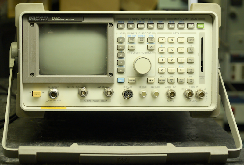
HP 8920A Transceiver Test Set
13 minute read
This post is part of the series 'Test Equipment':
 I came by this compact piece of test equipment back in January of this year (2025). For its size, it is surprisingly heavy at a shade over 17kg, leading me to believe that it had a linear power supply ... but that is not the case, it has a proprietary, off-the-shelf Switch Mode PSU made by Artesyn.
What makes the HP8920A so heavy is the fact that it is really a whole rack of test equipment, encompassing all the necessary 'bits' to test AM, FM and SSB transceivers, including mobile phones, all crammed into a very small space. To accomplish this, it includes a communications-grade signal generator with all the bells and whistles of a stand-alone generator. It includes a spectrum analyser with tracking-generator. It even includes an oscilloscope ... although, here I need to point out that this feature is really only intended for monitoring signals in the audio range. I could go on listing all the features ... but if you're reading this article, you probably have an 8920 and have already found the manual on-line.
I'm always very careful the first time I switch on something that I know has lain dormant for an undisclosed period. This piece of kit was no different from several items in my possession, in that it went bang as soon as I switched it on. Powering it via a variac would have made little difference since the internal SMPS is designed to operate between 85V and 265V. And switching PSUs can be a tad unpredictable when operated below their minimum supply voltage
The bang was immediately followed by a very familiar dead-capacitor smell and identifying which capacitor was not going to be easy since the SMPS needs to be removed in order to examine it.
And ... in order to remove the SMPS, one has to remove the 8920 outer case, obviously. Thereafter, the A23 unit (essentially the main RF module) first needs to be removed to allow the kinked plastic ON/Off actuator to be lifted out. Once you have done this (and it is no easy task), the screws retaining the SMPS can then be removed. Call me a cynic, but in these situations, I always look for a moulded Rifa capacitor. Again, not disappointed, it was very obvious that C7, 47nF/630V had exploded. Normally replacing such a capacitor would be relatively simple, but not here. Reason being, although the board is secured to the chassis by three screws, there are no less than ten plastic pillars with clips than need to be released. I'm sure the factory in Hong Kong has a tool for releasing all ten at once but it is possible to release them one by one whilst easing the board away from the chassis. There is also a daughter board plugged into the main board which needs to come off first.
I replaced C7 and whilst the board was off the chassis I replaced a couple of 10nF/100V Rifa capacitors which were cracked. The silk-screen on the board does not match the component designations on the schematic, but I think these were associated with the alternative 12V DC input.
Satisfied that there were no other damaged components on the board, I reassembled the PSU, refitted it and switched it on. It worked! And the monitor displayed a line informing me that all self tests had passed. Now to see if the 8920A was going to be of use to me. That perhaps sounds a bit brutal ... but typically, with the work that I do with vintage Racal kit, I'm looking for a minimum operating frequency of 100KHz (maybe a bit lower?) and an upper frequency of at least 30MHz.
HP made the 8920A configurable to the customer's needs. Thus there is a label on the back listing which 'mods' are fitted.
On this one, these are as follows ...
001 ............ High stability reference OCXO ...... Nice!
002 ............ Spectrum Analyzer
003 ............ GPIB
004 ............ Audio Signalling
005 ............ 512K RAM ... likely the default 256K plus an additional 256K.
010 ............ 400Hz High Pass Filter
012 ............ 4KHz Bandpass Filter
020 ............ Radio Interface ... since removed, but would have been of no use to me.
Not listed but definitely fitted ...
055 ............ 0.4-1000MHz mechanical input module (the A23 unit mentioned earlier) ...... very nice!
103 ............ DC Current Meter and Remote Programming
The A23 unit, referred to as the Electronic Input Module (option 009) restricts the RF Frequency range of the 8920A to 30MHz to 1000MHz.
With option 055 fitted, the A23 unit is known as the Mechanical Input Module and the RF Frequency Range is 400KHz to 1000MHz.
In my case, option 055 is definitely fitted. I can confirm that the lower frequency limit is not 30MHz and is actually useable below 100KHz ... which makes this particular 8920A a viable piece of test equipment for what I do.
However, something was wrong. The spectrum analyser was extremely deaf ... by about 60dB!!. The analyser is one of the plug-in modules and so not necessarily the faulty item. The actual culprit turned out to be the 5V line (or lack of it) from the secondary regulator board. Here, the 5V output is on a pin which is sleeved with heat-shrink ... and in this case, the wire had fractured within the heat-shrink ... easily sorted.
With that fixed, the spectrum analyser worked beautifully, with accurate power measurements. Further self tests hinted that something was not right with the two optional filters; options 010 and 012. These appeared to be missing. Because these are 'factory-fitted', and the diagnostics are not geared towards component-level repair, the location of these two filters was not instantly apparent. I eventually found them languishing on a small board mounted vertically behind the front panel, under a metal plate. These two filters are small daughter-boards which interface with the board via convenient header pins. I simply eased them up a bit then back down and re-ran the test ... The test passed. Conclusion? Localised tarnishing of the pins or sockets.
But there was still a lingering smell which probably did not bode well, and I had an MA79 project lined up for the bench, so the 8920 was temporarily put to one side.
After finishing the MA79G, I heaved the 8920 back onto the bench, removed the case and switched it on. There was a loud rasping noise from the SMPS with a large localised 'fireworks display' in the area adjacent to the 14-way connector. I switched it off.
So, the process of removing the SMPS was repeated ... and the board was again removed from the chassis. Apart from a very obvious acrid smell, there wasn't really anything instantly obvious. The arcing had appeared to come from the connector, but there was no evidence of damage or burning there. Neither was there any evidence of bulging capacitors. Then I noticed that one of the tall 470uF/50V electrolytics (C45) appeared to be raised up off the board slightly.
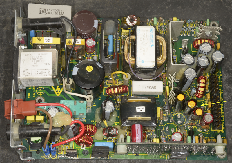
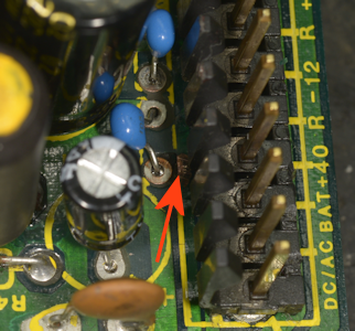
I removed the cluster of 470uF/50V capacitors associated with the +40V, +12V and -12V outputs. C45 on the -12V line, was the only one to resist extraction. This is highlighted by the arrow in the photograph above. When it did come away, one of the legs was still attached to the board and required some care to remove without damaging the through-hole plating. There was a lot of debris under C45 but I'm not convinced that the capacitor had actually ruptured. What I did notice was that there was a dark sticky residue under all four capacitors. I cleaned up the board and replaced all four capacitors, re-built the SMPS and re-installed it ... probably prematurely, as when I switched it on, I was greeted with the same fireworks display from the area around the 14-way connector. So, I stripped it down again. I was getting good at removing the board from the chassis by this time!
I then went looking for clues as to what might be the problem as I could not figure out why there was a massive arcing issue associated with the connector. A trawl of the internet yielded several statements indicating that the Artesyn SMPS in the 8920 was notorious for failing. That was a bit disconcerting, and not very encouraging. I found two videos, one of which although it was an SMPS from an 8920, the board was different ... so that was ignored. The other video was more promising ... same PCB as mine. All the guy did was replace every single electrolytic capacitor. Although to be fair, he had discovered a seriously bulging capacitor. I was also amused by his testing of the diodes on the board without isolating one end ... and when he came to test CR5, he initially declared it u/s as it measured 150 ohms in both directions ... and I'm wanting to shout 'there's a 150-ohm resistor across it!'. He must have read my mind because he then spotted the resistor. But surely he should have known that the 'diode test' on multimeters is NOT suitable for in-circuit testing.
In the top right corner of the schematic for the SMPS there is a revision list. So I decided to pay attention to this and verify that what I had was compliant with the final revision. The first change related to changing R7 from 750 ohms to 1000 ohms. Curiously, on the schematic, R7 is shown as 100 ohms and on my board it was 75 ohms ... hmmm? So I left it alone. The next change was changing R35 from 4K7/1W to 1K5/2W, and here I found that the 4K7 resistor on my board was open-circuit. R35 is a bleed-resistor across C31 (470uF/50V) on the output of the +40V line.
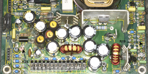
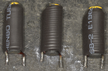
R35 was duly replaced with a 1K5/2W resistor (see left), and R19 was changed from 499K to 100K as per revision L. The three inductors (marked 'L') had been wrapped in black tape. Further examination revealed when the tape was removed that each was covered in the same black residue that had been found under the capacitors. I cleaned the inductors and replaced the tape with black heat-shrink.
The presence of the black residue was increasingly suspicious and I began to suspect that it was the cause of the arcing. I noticed that several of the 1uF/50V ceramic capacitors along the length of the 14-way connector looked burned, yet all tested good. I removed the five 1000uF/35V capacitors associated with the 5V line and found the same residue under them. There are four more 1000uF/35V capacitors on the board whose designations do not match anything on the schematic. These too also had the black residue under them. After the board was thoroughly cleaned with IPA and wiped dry with cotton buds, I replaced all the 1uF ceramic capacitors and electrolytics except the two big fat ones.
I had also noticed that the connector that mated with the 14-pin header had some of the black residue inside each receptacle ... very suspicious. Each contact was carefully extracted and cleaned , and the plastic part thoroughly cleaned and dried. I decided to try powering the board up on its own ... see what happened. I also opted to run it up via a variac. As I did this, I could hear the inverter attempting to start (little pings from the transformer). Then the meter attached to the +40V line registered 40V and surprise! surprise!, there was arcing adjacent to the 14-way connector.
This time though, it wasn't a big fat rasping flare like before. This time the arcing was limited to a localised arcing between a solder-pad and an adjacent track, almost underneath the 14-way connector. The solder-resist had been burned or scraped away and the track showed signs of scratching. Investigation showed that the track was sitting at +40V and the pad was at -12V, giving a potential difference of at least 52V ... the voltage varies with loading. I initially thought about daubing something on the exposed track but decided that cutting back the pad and the track to increase the gap was a more reliable solution.
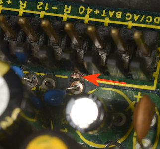
In fact, trimming about half a millimetre from the track and the pad was all that was required to stop the arcing, but I have to admit that the whole thing is bizarre ... and why had the solder-resist been scraped off the track?
My theory is that at some point someone dowsed the board or part of the board with a cleaning solvent. This solvent or whatever it was then found its way into the 14-way connector, under the 14-way header and under the tall electrolytic capacitors. Some of it even wicked its way up under the tape wound around the three inductors. It would only require some localised arcing to burn away some of the solder-resist/mask. Then perhaps someone tried to clean the board at that location by scratching away the remnants and carbon deposits ... unsuccessfully.
Anyway, the 8920A is all back together, is working perfectly and doesn't smell!
- Test Equipment for Test Equipment
- Two Adret Signal Generators
- Hewlett Packard HP1740A Repair
- HP 5065A Rubidium Vapour Frequency Standard
- HP 8920A Transceiver Test Set
April 2025
What makes the HP8920A so heavy is the fact that it is really a whole rack of test equipment, encompassing all the necessary 'bits' to test AM, FM and SSB transceivers, including mobile phones, all crammed into a very small space. To accomplish this, it includes a communications-grade signal generator with all the bells and whistles of a stand-alone generator. It includes a spectrum analyser with tracking-generator. It even includes an oscilloscope ... although, here I need to point out that this feature is really only intended for monitoring signals in the audio range. I could go on listing all the features ... but if you're reading this article, you probably have an 8920 and have already found the manual on-line.
I'm always very careful the first time I switch on something that I know has lain dormant for an undisclosed period. This piece of kit was no different from several items in my possession, in that it went bang as soon as I switched it on. Powering it via a variac would have made little difference since the internal SMPS is designed to operate between 85V and 265V. And switching PSUs can be a tad unpredictable when operated below their minimum supply voltage
The bang was immediately followed by a very familiar dead-capacitor smell and identifying which capacitor was not going to be easy since the SMPS needs to be removed in order to examine it.
And ... in order to remove the SMPS, one has to remove the 8920 outer case, obviously. Thereafter, the A23 unit (essentially the main RF module) first needs to be removed to allow the kinked plastic ON/Off actuator to be lifted out. Once you have done this (and it is no easy task), the screws retaining the SMPS can then be removed. Call me a cynic, but in these situations, I always look for a moulded Rifa capacitor. Again, not disappointed, it was very obvious that C7, 47nF/630V had exploded. Normally replacing such a capacitor would be relatively simple, but not here. Reason being, although the board is secured to the chassis by three screws, there are no less than ten plastic pillars with clips than need to be released. I'm sure the factory in Hong Kong has a tool for releasing all ten at once but it is possible to release them one by one whilst easing the board away from the chassis. There is also a daughter board plugged into the main board which needs to come off first.
I replaced C7 and whilst the board was off the chassis I replaced a couple of 10nF/100V Rifa capacitors which were cracked. The silk-screen on the board does not match the component designations on the schematic, but I think these were associated with the alternative 12V DC input.
Satisfied that there were no other damaged components on the board, I reassembled the PSU, refitted it and switched it on. It worked! And the monitor displayed a line informing me that all self tests had passed. Now to see if the 8920A was going to be of use to me. That perhaps sounds a bit brutal ... but typically, with the work that I do with vintage Racal kit, I'm looking for a minimum operating frequency of 100KHz (maybe a bit lower?) and an upper frequency of at least 30MHz.
HP made the 8920A configurable to the customer's needs. Thus there is a label on the back listing which 'mods' are fitted.
On this one, these are as follows ...
001 ............ High stability reference OCXO ...... Nice!
002 ............ Spectrum Analyzer
003 ............ GPIB
004 ............ Audio Signalling
005 ............ 512K RAM ... likely the default 256K plus an additional 256K.
010 ............ 400Hz High Pass Filter
012 ............ 4KHz Bandpass Filter
020 ............ Radio Interface ... since removed, but would have been of no use to me.
Not listed but definitely fitted ...
055 ............ 0.4-1000MHz mechanical input module (the A23 unit mentioned earlier) ...... very nice!
103 ............ DC Current Meter and Remote Programming
The A23 unit, referred to as the Electronic Input Module (option 009) restricts the RF Frequency range of the 8920A to 30MHz to 1000MHz.
With option 055 fitted, the A23 unit is known as the Mechanical Input Module and the RF Frequency Range is 400KHz to 1000MHz.
In my case, option 055 is definitely fitted. I can confirm that the lower frequency limit is not 30MHz and is actually useable below 100KHz ... which makes this particular 8920A a viable piece of test equipment for what I do.
However, something was wrong. The spectrum analyser was extremely deaf ... by about 60dB!!. The analyser is one of the plug-in modules and so not necessarily the faulty item. The actual culprit turned out to be the 5V line (or lack of it) from the secondary regulator board. Here, the 5V output is on a pin which is sleeved with heat-shrink ... and in this case, the wire had fractured within the heat-shrink ... easily sorted.
With that fixed, the spectrum analyser worked beautifully, with accurate power measurements. Further self tests hinted that something was not right with the two optional filters; options 010 and 012. These appeared to be missing. Because these are 'factory-fitted', and the diagnostics are not geared towards component-level repair, the location of these two filters was not instantly apparent. I eventually found them languishing on a small board mounted vertically behind the front panel, under a metal plate. These two filters are small daughter-boards which interface with the board via convenient header pins. I simply eased them up a bit then back down and re-ran the test ... The test passed. Conclusion? Localised tarnishing of the pins or sockets.
But there was still a lingering smell which probably did not bode well, and I had an MA79 project lined up for the bench, so the 8920 was temporarily put to one side.
After finishing the MA79G, I heaved the 8920 back onto the bench, removed the case and switched it on. There was a loud rasping noise from the SMPS with a large localised 'fireworks display' in the area adjacent to the 14-way connector. I switched it off.
So, the process of removing the SMPS was repeated ... and the board was again removed from the chassis. Apart from a very obvious acrid smell, there wasn't really anything instantly obvious. The arcing had appeared to come from the connector, but there was no evidence of damage or burning there. Neither was there any evidence of bulging capacitors. Then I noticed that one of the tall 470uF/50V electrolytics (C45) appeared to be raised up off the board slightly.
I removed the cluster of 470uF/50V capacitors associated with the +40V, +12V and -12V outputs. C45 on the -12V line, was the only one to resist extraction. This is highlighted by the arrow in the photograph above. When it did come away, one of the legs was still attached to the board and required some care to remove without damaging the through-hole plating. There was a lot of debris under C45 but I'm not convinced that the capacitor had actually ruptured. What I did notice was that there was a dark sticky residue under all four capacitors. I cleaned up the board and replaced all four capacitors, re-built the SMPS and re-installed it ... probably prematurely, as when I switched it on, I was greeted with the same fireworks display from the area around the 14-way connector. So, I stripped it down again. I was getting good at removing the board from the chassis by this time!
I then went looking for clues as to what might be the problem as I could not figure out why there was a massive arcing issue associated with the connector. A trawl of the internet yielded several statements indicating that the Artesyn SMPS in the 8920 was notorious for failing. That was a bit disconcerting, and not very encouraging. I found two videos, one of which although it was an SMPS from an 8920, the board was different ... so that was ignored. The other video was more promising ... same PCB as mine. All the guy did was replace every single electrolytic capacitor. Although to be fair, he had discovered a seriously bulging capacitor. I was also amused by his testing of the diodes on the board without isolating one end ... and when he came to test CR5, he initially declared it u/s as it measured 150 ohms in both directions ... and I'm wanting to shout 'there's a 150-ohm resistor across it!'. He must have read my mind because he then spotted the resistor. But surely he should have known that the 'diode test' on multimeters is NOT suitable for in-circuit testing.
In the top right corner of the schematic for the SMPS there is a revision list. So I decided to pay attention to this and verify that what I had was compliant with the final revision. The first change related to changing R7 from 750 ohms to 1000 ohms. Curiously, on the schematic, R7 is shown as 100 ohms and on my board it was 75 ohms ... hmmm? So I left it alone. The next change was changing R35 from 4K7/1W to 1K5/2W, and here I found that the 4K7 resistor on my board was open-circuit. R35 is a bleed-resistor across C31 (470uF/50V) on the output of the +40V line.
R35 was duly replaced with a 1K5/2W resistor (see left), and R19 was changed from 499K to 100K as per revision L. The three inductors (marked 'L') had been wrapped in black tape. Further examination revealed when the tape was removed that each was covered in the same black residue that had been found under the capacitors. I cleaned the inductors and replaced the tape with black heat-shrink.
The presence of the black residue was increasingly suspicious and I began to suspect that it was the cause of the arcing. I noticed that several of the 1uF/50V ceramic capacitors along the length of the 14-way connector looked burned, yet all tested good. I removed the five 1000uF/35V capacitors associated with the 5V line and found the same residue under them. There are four more 1000uF/35V capacitors on the board whose designations do not match anything on the schematic. These too also had the black residue under them. After the board was thoroughly cleaned with IPA and wiped dry with cotton buds, I replaced all the 1uF ceramic capacitors and electrolytics except the two big fat ones.
I had also noticed that the connector that mated with the 14-pin header had some of the black residue inside each receptacle ... very suspicious. Each contact was carefully extracted and cleaned , and the plastic part thoroughly cleaned and dried. I decided to try powering the board up on its own ... see what happened. I also opted to run it up via a variac. As I did this, I could hear the inverter attempting to start (little pings from the transformer). Then the meter attached to the +40V line registered 40V and surprise! surprise!, there was arcing adjacent to the 14-way connector.
This time though, it wasn't a big fat rasping flare like before. This time the arcing was limited to a localised arcing between a solder-pad and an adjacent track, almost underneath the 14-way connector. The solder-resist had been burned or scraped away and the track showed signs of scratching. Investigation showed that the track was sitting at +40V and the pad was at -12V, giving a potential difference of at least 52V ... the voltage varies with loading. I initially thought about daubing something on the exposed track but decided that cutting back the pad and the track to increase the gap was a more reliable solution.
In fact, trimming about half a millimetre from the track and the pad was all that was required to stop the arcing, but I have to admit that the whole thing is bizarre ... and why had the solder-resist been scraped off the track?
My theory is that at some point someone dowsed the board or part of the board with a cleaning solvent. This solvent or whatever it was then found its way into the 14-way connector, under the 14-way header and under the tall electrolytic capacitors. Some of it even wicked its way up under the tape wound around the three inductors. It would only require some localised arcing to burn away some of the solder-resist/mask. Then perhaps someone tried to clean the board at that location by scratching away the remnants and carbon deposits ... unsuccessfully.
Anyway, the 8920A is all back together, is working perfectly and doesn't smell!
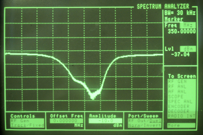
Tracking Generator function, K&L variable Notch Filter at 350MHz.
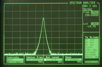
Spectrum Analyser function, 150MHz signal at -20dBm.