Magnum 3AS0523 Braille Receiver
5 minute read
April 2026
Last year I was asked if I might be prepared to take on the job of repairing and refurbishing (essentially, making safe!) several very old domestic radios. This article describes the first and only receiver that I managed to get working out of a 'batch' of four. More on the reason for this later.
Burne-Jones and Co. produced domestic radio receivers between 1923 and 1947, and a range of Crystal Sets between 1929 and 1935. Initially their valve-based receivers were of the early TRF design. These tended to be battery-operated.
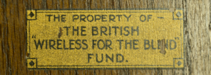
This specimen, like most of Burne-Jones's receivers was specifically manufactured for The British Wireless For The Blind Fund ... hence the distinct lack of aesthetics or labelling. The year of manufacture is still to be confirmed. I know that in 1937, Burne-Jones produced the Magnum type 3S5739 (I think) which was of TRF design. Then around 1946 or 1947 they produced a Superhet receiver almost identical to the type 3AS0523. The only difference being that the latter used I-Octal-base valves throughout, whereas in the 3AS0523 the first three valves are B7-base, whilst the Rectifier has a B4-base. Otherwise, the schematic for both receivers is almost identical, thus placing the Magnum type 3AS0523 between 1937 and 1946.
3AS0523 valve line-up ...
V1: FC4, B7-base, an Octode ... likely predecessor of the Triode-Hexode.
V2: VP4B, B7-base, a variable-μ Pentode.
V3: PEN4DD, B7-base, a Double Diode Pentode.
V4: IW4/350, B4-base, Full-Wave Rectifier with indirectly-heated Cathode.
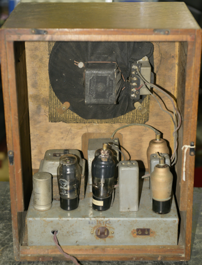
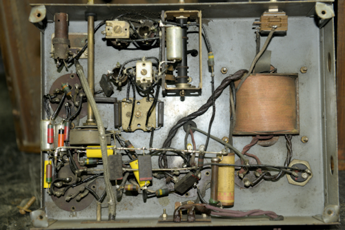
Left: The inside of the Magnum 3AS0523. The fibre rear cover was missing. Note the three wires going from the chassis to the transformer mounted on the loudspeaker. With reference to the schematic diagram, smoothing choke L6 is formed from a section of the primary winding of the audio output transformer.
Six of the original paper capacitors had already been replaced. Given that three were Sprague Vitamin-Q types from 1974, I decided that at over 50 years old, they ought to be replaced with modern polypropylene types. With the exception of R10, all the carbon resistors were replaced with modern 1W carbon or metal film types. R10 was replaced with a 150R wire-wound resistor. C7 (50μF) was replaced with a modern 47μF/63V aluminium type.
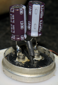
Right: The smoothing pack was re-stuffed with a pair of modern radial 8μ2/450V aluminium types. I was able to cut the can open in such a way that the top section slipped firmly over the narrow section without any requirement to glue it together.
The wave-band switch required some TLC, having had one of its cam-operated contacts severely bent. After that, I slowly applied mains voltage via a variac and was rewarded with a working receiver ... albeit with constrained audio and a tendency to 'hoot' when tuning across a station.
I decided that someone had been 'playing' with the tuning of the I.F. transformers T1 and T2. I took a guess that like other Burne-Jones Magnum receivers of the same age, this receiver should have an I.F. of 465KHz. I was not wrong. After tuning each transformer to 465KHz the hooting stopped and the constrained audio resolved into rich pleasant tones. But there was another issue ...
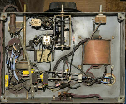
As soon as the chassis was mounted back in the wooden case it stopped working. On taking the chassis out of the box, it burst into life again. This turned out to be an electrical failure caused by a mechanical failure. I found that the extension to one end or R12, which delivers the AGC voltage to V1 via L3 and L2, was intermittent. The original joint was hidden within the long length of woven insulation. If you look at the two under-chassis photographs above, you will notice that the four corner brackets for the four mounting screws are NOT level or parallel to the top of the chassis. Thus when the screws were tightened, they distorted the chassis just enough to pull the connection inside the sleeving apart. Once this joint was re-soldered, the receiver worked when the chassis was attached to the case.
Buoyed with this success, I turned my attention to an old Invicta 31. This one proved to be a veritable nightmare. Someone had rammed the output pentode (EBL31) into its Paxolin IO socket incorrectly, such that all the pins were one position out!! With that resolved (miraculously no damage tot he valve), it still didn't work. The HT volts was extremely low and there was a smell of something getting very hot. There were sparks too. Oddly there was arching between some of the terminals on V1 (ECH35) to the centre plastic spigot! WHAT?! I concluded that there was something seriously amiss around the ECH35. SO I put the Old Invicta to one side. I then tackled an HMV1121 and discovered that its mains transformer had an open circuit primary winding.
Reluctantly, I concluded that my friend got himself a load of radios that someone had failed to get working and then abandoned. I made the executive decision that such things were no longer economically viable.
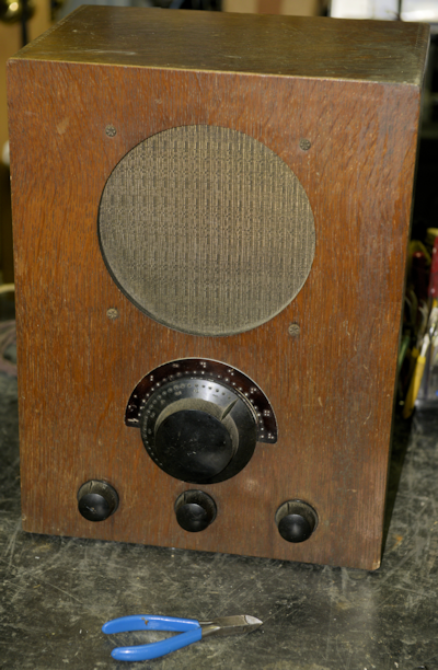
Burne-Jones Magnum type 3AS0523.
Burne-Jones and Co. produced domestic radio receivers between 1923 and 1947, and a range of Crystal Sets between 1929 and 1935. Initially their valve-based receivers were of the early TRF design. These tended to be battery-operated.
This specimen, like most of Burne-Jones's receivers was specifically manufactured for The British Wireless For The Blind Fund ... hence the distinct lack of aesthetics or labelling. The year of manufacture is still to be confirmed. I know that in 1937, Burne-Jones produced the Magnum type 3S5739 (I think) which was of TRF design. Then around 1946 or 1947 they produced a Superhet receiver almost identical to the type 3AS0523. The only difference being that the latter used I-Octal-base valves throughout, whereas in the 3AS0523 the first three valves are B7-base, whilst the Rectifier has a B4-base. Otherwise, the schematic for both receivers is almost identical, thus placing the Magnum type 3AS0523 between 1937 and 1946.
3AS0523 valve line-up ...
V1: FC4, B7-base, an Octode ... likely predecessor of the Triode-Hexode.
V2: VP4B, B7-base, a variable-μ Pentode.
V3: PEN4DD, B7-base, a Double Diode Pentode.
V4: IW4/350, B4-base, Full-Wave Rectifier with indirectly-heated Cathode.
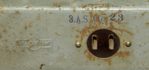
Brand and Model Number on rear.
Left: The inside of the Magnum 3AS0523. The fibre rear cover was missing. Note the three wires going from the chassis to the transformer mounted on the loudspeaker. With reference to the schematic diagram, smoothing choke L6 is formed from a section of the primary winding of the audio output transformer.
Under-chassis components before refurbishment.
Under-chassis components after refurbishment.
Six of the original paper capacitors had already been replaced. Given that three were Sprague Vitamin-Q types from 1974, I decided that at over 50 years old, they ought to be replaced with modern polypropylene types. With the exception of R10, all the carbon resistors were replaced with modern 1W carbon or metal film types. R10 was replaced with a 150R wire-wound resistor. C7 (50μF) was replaced with a modern 47μF/63V aluminium type.
Right: The smoothing pack was re-stuffed with a pair of modern radial 8μ2/450V aluminium types. I was able to cut the can open in such a way that the top section slipped firmly over the narrow section without any requirement to glue it together.
The wave-band switch required some TLC, having had one of its cam-operated contacts severely bent. After that, I slowly applied mains voltage via a variac and was rewarded with a working receiver ... albeit with constrained audio and a tendency to 'hoot' when tuning across a station.
I decided that someone had been 'playing' with the tuning of the I.F. transformers T1 and T2. I took a guess that like other Burne-Jones Magnum receivers of the same age, this receiver should have an I.F. of 465KHz. I was not wrong. After tuning each transformer to 465KHz the hooting stopped and the constrained audio resolved into rich pleasant tones. But there was another issue ...
As soon as the chassis was mounted back in the wooden case it stopped working. On taking the chassis out of the box, it burst into life again. This turned out to be an electrical failure caused by a mechanical failure. I found that the extension to one end or R12, which delivers the AGC voltage to V1 via L3 and L2, was intermittent. The original joint was hidden within the long length of woven insulation. If you look at the two under-chassis photographs above, you will notice that the four corner brackets for the four mounting screws are NOT level or parallel to the top of the chassis. Thus when the screws were tightened, they distorted the chassis just enough to pull the connection inside the sleeving apart. Once this joint was re-soldered, the receiver worked when the chassis was attached to the case.
Buoyed with this success, I turned my attention to an old Invicta 31. This one proved to be a veritable nightmare. Someone had rammed the output pentode (EBL31) into its Paxolin IO socket incorrectly, such that all the pins were one position out!! With that resolved (miraculously no damage tot he valve), it still didn't work. The HT volts was extremely low and there was a smell of something getting very hot. There were sparks too. Oddly there was arching between some of the terminals on V1 (ECH35) to the centre plastic spigot! WHAT?! I concluded that there was something seriously amiss around the ECH35. SO I put the Old Invicta to one side. I then tackled an HMV1121 and discovered that its mains transformer had an open circuit primary winding.
Reluctantly, I concluded that my friend got himself a load of radios that someone had failed to get working and then abandoned. I made the executive decision that such things were no longer economically viable.