RA217 + MA323 = RA329
15 minute read
This post is part of the series 'Racal's early solid-state receivers':
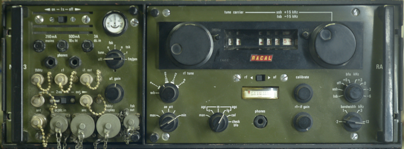 Last year, I think it was some time in October, a good friend of mine asked if I would 'look at' a couple of RA329s for him. As I am a sucker for challenges, I said yes, even though I was already snowed under with other Racal projects. The RA329 comprises an RA217D and an MA323. The latter is little more than a glorified interface panel that adds FSK and FM to the RA217. As you can see from the photograph above, it is green, therefore it stays on the ground. The RA329 was designed to be vehicle-mounted, with many being fitted in Land Rovers and trucks.
Designed in South Africa (source - Radio Bygones article by Brian Austin), the RA217 was Racal's intended transistorised replacement for the RA17, although the internal architecture is based on that of the RA117. Due to the use of Germanium transistors, it's performance was inferior to the RA17 and RA117 and it was not popular. One reason for it's unpopularity being that the MHz and KHz controls are swapped.
Both the RA329s that I was handed were faulty. Both appeared deaf, and one exhibited extreme audio distortion. The AGC system in the RA217 and RA1217 is a complex affair that actually involves two circuits which must be correctly set up, otherwise the audio is distorted and the panel meter doesn't operate correctly. This, I learned from repairing my own RA1217 back in 2010. So, the first thing I did was attempt to verify that the AGC systems were correctly set up ... and it was then that I realised that the RA217, albeit beautifully engineered, little thought had gone into making it easy to work on. Not only was the RA217 promising to be awkward, taking the RA329 apart was also headache inducing!
An RA329 installation is a rack within a rack ... making it extremely heavy. Fortunately, I didn't have the outer rack to contend with. Finding a manual was easy, however finding one for the RA217D was another matter. The RA329 manual that I initially downloaded included the manual for the RA217, not the RA217D. Obtaining the latter required taking out a free month's subscription to SCRIBD as that appears to be the only source of a manual for the RA217D. The difference between the 217 and the 217D will be discussed in due course. Meanwhile, I had discovered that in the absence of multiple extender cables as shown in the manual, I was going to have to remove the complicated wiring harness that links the RA217D to the MA323. Essentially the RA217D will not work without the MA323 ... and since the harness is integrated into the rack, both units have to be in the rack in order to function. You can see where I'm going here?
An RA217 could be described as an RA1217 cut down the middle then one half placed on top of the other. Only, the RA217 came before the RA1217, so it's the other way round. In both radios, the RF unit is on the left when viewed from the front. Getting access to the RF unit in the RA217D is extremely awkward, if not impossible whilst the RA217D is in the RA329 rack ... hence all the extender cables in the manual. Since I had two RA329s at my disposal, I decided to completely strip one down and make use of the wiring harness. That way I could connect both the MA323 and RA217D out-with the confines of the rack and at the same time be able to access all parts of the RA217D.
Getting the wiring harness out is easier said than done. Assuming you have a complete unit, the alignment plate at the rear needs to be removed first. This is the plate which ensures that the inner rack correctly aligns with the outer rack. With that plate off, we now have to remove the rear frame which fits between the two side panels. Only now can we access the wiring harness, which itself is mounted on two guide plates. Two 2BA screws hold the two 'halves' together and a further four 2BA screws secure the two plates to the side panels.
With the harness now free, I experimented with moving the RA217 around. It was still awkward, but with care, access to all points on the RA217D were ultimately accessible. Accessing the AGC voltage at the RF Unit front end was proving decidedly frustrating when two things happened which were to set me back several weeks. The first was the arrival of a pair of Park Air Electronics 3010 Air Band transceivers (each weighing 32Kg!) for repair/investigation. These automatically took priority over the RA329s which were low priority. The second thing that happened was an unplanned five-day vacation in hospital and subsequent surgery which resulted in a six-week ban on lifting heavy items! The PAE 3000 series of Air-Band transceivers will be covered in a later article on this website.
Now into Early January 2026, and the two PAE 3010s repaired and returned to their owner, I re-visited the faulty RA217Ds. I discovered that I had two 'different' RA217s. By that I mean that the one with the higher serial number employed the later version of the Calibrator. See below ...
Also, the earlier RA217D had developed another fault. It was now blowing the 250mA Mains Fuse in the MA323 when the AC input exceeded 150V. This turned out to be a faulty PSU. Apart from 24V for the two dial lights, the RA217D runs from a single 16V supply, so I made up a lead with a 15-way D-type connector to replace the PSU, allowing me to power it from an external power supply. In both receivers, the Calibrator was working, so that automatically ruled out issues with the 2nd VFO. It was when turning the later RA217D over that I was conscious of a light 'knock'. Such a thing is normally indicative of something loose inside. And indeed there was. The knock appeared to be from the IF module.
On opening up the IF Module it was immediately obvious what was loose. L2, part of the low-pass filter on the input of VT3 on the Detector board had become detached from the board, mechanically and electrically. This is an inductor formed on a small binocular ferrite using what looks like 40 s.w.g. wire ... very thin! The ferrite was at one time glued to the board, but the glue had obviously failed and excessive movement and or g-forces had likely jerked the very fine wires causing them to snap.
Repair was relatively simple. Two short lengths of 40 s.w.g. wire were soldered to the the existing wires. I turned the ferrite upside-down and glued it to the board, This allowed for the wires to be looped back down through the existing holes. On powering up the RA217D, the receiver was found to be functioning perfectly. One down, one to go!
Coincidentally, ignoring the faulty power supply, the fault on the other (earlier) RA217D turned out to be very similar. Having already ascertained that the 2nd VFO was not an issue. And since there was distinctive 'chuffing' audible when the MHz control was turned, the 1st VFO and 2nd Mixer were thus ruled out as being at fault. Chasing a signal through the RF unit quickly identified the location of the fault. The Preselector was functioning, but there was very little signal present at PL1, the output of the RF Unit. Unlike in the RA1217 where everything is instantly accessible, the RF amplifier and Preselector in the RA217 is effectively folded up to fit inside a cuboid enclosure.
It was whilst peering into the gap between the PC board and the Preselector that I noticed that one of the ferrite components appeared out of place. Further examination revealed that this was 3T2, in the Collector circuit of 3VT3, the second RF amplifier, and one end of it had become detached from the PCB. As with the inductor on the Detector board, this was formed from 40 s.w.g. wire on a small binocular ferrite. As with the Detector board, this ferrite had originally been glued to the board but was now hanging free, secured by two of its three wires.
The photograph on the left shows just how awkward it is to gain access to the components on the RF Amplifier board. The board is mounted on its side and secured to two pillars with four 6BA screws. Two of these are relatively easy to remove, but the other two, closest to the chassis are incredibly difficult to access. I eventually managed to take all four screws out, and although the attached wiring severely restricts the movement of the board, I was able to get just enough movement to enable me to clear the hole left by the broken wire. Once that was done, I attached a length of 40 s.w.g. wire to the end of 3T2 and after much frustration and 'blue air', I finally coaxed the end through the hole and soldered it in place. A dab of Superglue then secured the transformer to the board and the latter was then re-attached to the pillars.
On retesting the receiver, all was looking good but it was clear that the AGC system needed setting up. The meter wasn't behaving correctly and the detector was being over-driven. As mentioned earlier, there are two parts to the AGC circuit. The main 'component' is on the AGC board in the IF module. To set this part up, the input to the IF is removed and RV1 on the AGC board is adjusted for -4V at pin 3 of the 1.6MHz Amplifier board. Now re-connect the input to the IF Module and verify that -4V is present at the junction of 4R3 and 4C4 on the small PCB next to the RF Unit. See below ...
Who on earth thought it was a good idea to put this little board here! Connecting to the junction of 4R3 and 4C4 is tricky enough, but for setting up the AGC here, with an input signal of 10mV e.m.f., the potentiometer on this little board should be adjusted such that the voltage at 3VT1 Collector just 'bottoms'. Accessing 3VT1 is tricky with care ... BUT adjusting potentiometer 4RV1 is almost impossible. I tried all sorts of trim tools and screwdrivers of differing lengths before I found a trim tool clamped to the rear of the front panel which might just be the one for this purpose ... but it is still a very hit or miss affair. Afterwards, like the other receiver, this one performed perfectly.
Now to find what is wrong with the power supply ...
There are actually no less than three different Power Supply Units found across the RA1217/RA217 range. For the RA1217, the PSU is type PU1153. For the RA217, the PSU is type PU408. But for the RA217D, it is the PU410 that slots into the hole at the bottom of the rear panel. Unlike the other two PSUs, the PU410 is unique in that it is an SMPS. And dating from 1966, this has to be the earliest example of a Switch Mode PSU that I have come across. Unlike many of today's modern SMPSs which will happily run on any AC supply from 100V to 250V. This one has three options ... 125V AC, 250V AC, or 9 - 30V DC.
When operating from an AC supply, the two primary windings of the conventional transformer are either in series or parallel. The single secondary winding generates nominally 24V DC after full wave rectification.
This 24V DC feeds the primary winding of the SMPS transformer via a chopper circuit. This makes so much sense since the RA329 is designed for vehicle installations where the only source of current is either 12V or 24V. Thus when the voltage selector is set to DC, the rectified output of T1 is disconnected and the input to the chopper circuit is connected across the external DC supply. So why had the PSU started blowing the AC input fuse?
Ask anyone with experience repairing SMPSs and they will more often than not tell you to check the capacitors ... which I did, and they all checked out very healthy. I then isolated every transistor and diode ... and they all checked out OK. Then I realised that I hadn't checked out the bridge rectifier. That was because, unlike everything else, it was hidden. I found it loosely clamped to the side of T1, under the chopper board. It was quite a small device (see right), being only about 1cm square. When I examined the wiring to it, I found that the rubber insulation was brick hard. Over-heating maybe? Slightly worrying, there was evidence that some solder had run down one of the legs, inside the rubber insulation, towards the body of the rectifier. The date code on it was for week 26 of 1966. I figured it might be Germanium and not as robust as Silicon but it turns out it is Silicon. Maybe it was time to replace it? After removing the rubber insulation and de-soldering the wires, I checked it and found that one of the four diodes was showing as a low value resistor.
I fitted an 8A bridge rectifier, and since the faulty one had only been loosely attached to the transformer, I chose not to worry about heatsinking ... and who uses a transformer as a heatsink anyway? Bingo! It worked ... no blown Mains fuse ... and a perfectly working RA217D!
Some photographs of the inside of the RA217D ...
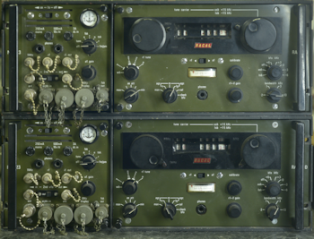
On the left is a photograph of the two RA329s. The one on the bottom is the older of the two and the one which had the faulty PSU. It should be added that the RA217D in this one had clearly been giving someone a few headaches. Out of the four main front panel screws, only two were fitted and only one was correct. The IF Unit cover had been removed and when replaced the one short screw was in the wrong place. Thus a long screw was in its place and in danger of causing a short.
I revisited the faulty rectifier and found it to be showing OK on my component analyser ... but I wouldn't trust it.
- The Racal RA1217
- A new 1MHz Osc. for the RA1217
- The Racal RA1218, and more ... or, what happened to the RA1219?
- RA217 + MA323 = RA329
January 2026
Designed in South Africa (source - Radio Bygones article by Brian Austin), the RA217 was Racal's intended transistorised replacement for the RA17, although the internal architecture is based on that of the RA117. Due to the use of Germanium transistors, it's performance was inferior to the RA17 and RA117 and it was not popular. One reason for it's unpopularity being that the MHz and KHz controls are swapped.
Both the RA329s that I was handed were faulty. Both appeared deaf, and one exhibited extreme audio distortion. The AGC system in the RA217 and RA1217 is a complex affair that actually involves two circuits which must be correctly set up, otherwise the audio is distorted and the panel meter doesn't operate correctly. This, I learned from repairing my own RA1217 back in 2010. So, the first thing I did was attempt to verify that the AGC systems were correctly set up ... and it was then that I realised that the RA217, albeit beautifully engineered, little thought had gone into making it easy to work on. Not only was the RA217 promising to be awkward, taking the RA329 apart was also headache inducing!
An RA329 installation is a rack within a rack ... making it extremely heavy. Fortunately, I didn't have the outer rack to contend with. Finding a manual was easy, however finding one for the RA217D was another matter. The RA329 manual that I initially downloaded included the manual for the RA217, not the RA217D. Obtaining the latter required taking out a free month's subscription to SCRIBD as that appears to be the only source of a manual for the RA217D. The difference between the 217 and the 217D will be discussed in due course. Meanwhile, I had discovered that in the absence of multiple extender cables as shown in the manual, I was going to have to remove the complicated wiring harness that links the RA217D to the MA323. Essentially the RA217D will not work without the MA323 ... and since the harness is integrated into the rack, both units have to be in the rack in order to function. You can see where I'm going here?
An RA217 could be described as an RA1217 cut down the middle then one half placed on top of the other. Only, the RA217 came before the RA1217, so it's the other way round. In both radios, the RF unit is on the left when viewed from the front. Getting access to the RF unit in the RA217D is extremely awkward, if not impossible whilst the RA217D is in the RA329 rack ... hence all the extender cables in the manual. Since I had two RA329s at my disposal, I decided to completely strip one down and make use of the wiring harness. That way I could connect both the MA323 and RA217D out-with the confines of the rack and at the same time be able to access all parts of the RA217D.
Getting the wiring harness out is easier said than done. Assuming you have a complete unit, the alignment plate at the rear needs to be removed first. This is the plate which ensures that the inner rack correctly aligns with the outer rack. With that plate off, we now have to remove the rear frame which fits between the two side panels. Only now can we access the wiring harness, which itself is mounted on two guide plates. Two 2BA screws hold the two 'halves' together and a further four 2BA screws secure the two plates to the side panels.
With the harness now free, I experimented with moving the RA217 around. It was still awkward, but with care, access to all points on the RA217D were ultimately accessible. Accessing the AGC voltage at the RF Unit front end was proving decidedly frustrating when two things happened which were to set me back several weeks. The first was the arrival of a pair of Park Air Electronics 3010 Air Band transceivers (each weighing 32Kg!) for repair/investigation. These automatically took priority over the RA329s which were low priority. The second thing that happened was an unplanned five-day vacation in hospital and subsequent surgery which resulted in a six-week ban on lifting heavy items! The PAE 3000 series of Air-Band transceivers will be covered in a later article on this website.
Now into Early January 2026, and the two PAE 3010s repaired and returned to their owner, I re-visited the faulty RA217Ds. I discovered that I had two 'different' RA217s. By that I mean that the one with the higher serial number employed the later version of the Calibrator. See below ...
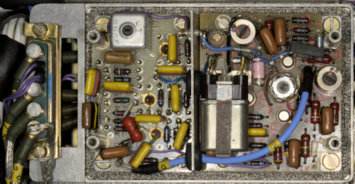
Original Calibrator with Regenerative divider.
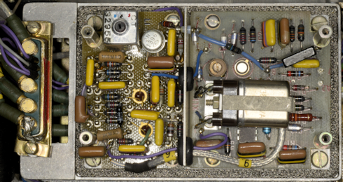
Later Calibrator with RTL-based divide-by-10 circuit.
Also, the earlier RA217D had developed another fault. It was now blowing the 250mA Mains Fuse in the MA323 when the AC input exceeded 150V. This turned out to be a faulty PSU. Apart from 24V for the two dial lights, the RA217D runs from a single 16V supply, so I made up a lead with a 15-way D-type connector to replace the PSU, allowing me to power it from an external power supply. In both receivers, the Calibrator was working, so that automatically ruled out issues with the 2nd VFO. It was when turning the later RA217D over that I was conscious of a light 'knock'. Such a thing is normally indicative of something loose inside. And indeed there was. The knock appeared to be from the IF module.
Detector Board with missing inductor.
On opening up the IF Module it was immediately obvious what was loose. L2, part of the low-pass filter on the input of VT3 on the Detector board had become detached from the board, mechanically and electrically. This is an inductor formed on a small binocular ferrite using what looks like 40 s.w.g. wire ... very thin! The ferrite was at one time glued to the board, but the glue had obviously failed and excessive movement and or g-forces had likely jerked the very fine wires causing them to snap.
The missing L2.
Repair was relatively simple. Two short lengths of 40 s.w.g. wire were soldered to the the existing wires. I turned the ferrite upside-down and glued it to the board, This allowed for the wires to be looped back down through the existing holes. On powering up the RA217D, the receiver was found to be functioning perfectly. One down, one to go!
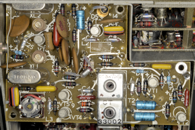
Coincidentally, ignoring the faulty power supply, the fault on the other (earlier) RA217D turned out to be very similar. Having already ascertained that the 2nd VFO was not an issue. And since there was distinctive 'chuffing' audible when the MHz control was turned, the 1st VFO and 2nd Mixer were thus ruled out as being at fault. Chasing a signal through the RF unit quickly identified the location of the fault. The Preselector was functioning, but there was very little signal present at PL1, the output of the RF Unit. Unlike in the RA1217 where everything is instantly accessible, the RF amplifier and Preselector in the RA217 is effectively folded up to fit inside a cuboid enclosure.
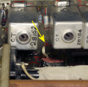
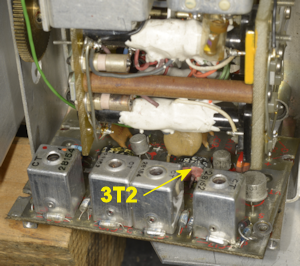
3T2 disconnected.
It was whilst peering into the gap between the PC board and the Preselector that I noticed that one of the ferrite components appeared out of place. Further examination revealed that this was 3T2, in the Collector circuit of 3VT3, the second RF amplifier, and one end of it had become detached from the PCB. As with the inductor on the Detector board, this was formed from 40 s.w.g. wire on a small binocular ferrite. As with the Detector board, this ferrite had originally been glued to the board but was now hanging free, secured by two of its three wires.
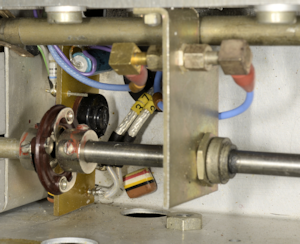
3T2 repaired, but board still to be re-attached.
The photograph on the left shows just how awkward it is to gain access to the components on the RF Amplifier board. The board is mounted on its side and secured to two pillars with four 6BA screws. Two of these are relatively easy to remove, but the other two, closest to the chassis are incredibly difficult to access. I eventually managed to take all four screws out, and although the attached wiring severely restricts the movement of the board, I was able to get just enough movement to enable me to clear the hole left by the broken wire. Once that was done, I attached a length of 40 s.w.g. wire to the end of 3T2 and after much frustration and 'blue air', I finally coaxed the end through the hole and soldered it in place. A dab of Superglue then secured the transformer to the board and the latter was then re-attached to the pillars.
On retesting the receiver, all was looking good but it was clear that the AGC system needed setting up. The meter wasn't behaving correctly and the detector was being over-driven. As mentioned earlier, there are two parts to the AGC circuit. The main 'component' is on the AGC board in the IF module. To set this part up, the input to the IF is removed and RV1 on the AGC board is adjusted for -4V at pin 3 of the 1.6MHz Amplifier board. Now re-connect the input to the IF Module and verify that -4V is present at the junction of 4R3 and 4C4 on the small PCB next to the RF Unit. See below ...
RF Unit AGC Input Board.
Who on earth thought it was a good idea to put this little board here! Connecting to the junction of 4R3 and 4C4 is tricky enough, but for setting up the AGC here, with an input signal of 10mV e.m.f., the potentiometer on this little board should be adjusted such that the voltage at 3VT1 Collector just 'bottoms'. Accessing 3VT1 is tricky with care ... BUT adjusting potentiometer 4RV1 is almost impossible. I tried all sorts of trim tools and screwdrivers of differing lengths before I found a trim tool clamped to the rear of the front panel which might just be the one for this purpose ... but it is still a very hit or miss affair. Afterwards, like the other receiver, this one performed perfectly.
Now to find what is wrong with the power supply ...
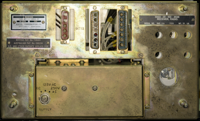
RA217D rear.
There are actually no less than three different Power Supply Units found across the RA1217/RA217 range. For the RA1217, the PSU is type PU1153. For the RA217, the PSU is type PU408. But for the RA217D, it is the PU410 that slots into the hole at the bottom of the rear panel. Unlike the other two PSUs, the PU410 is unique in that it is an SMPS. And dating from 1966, this has to be the earliest example of a Switch Mode PSU that I have come across. Unlike many of today's modern SMPSs which will happily run on any AC supply from 100V to 250V. This one has three options ... 125V AC, 250V AC, or 9 - 30V DC.
When operating from an AC supply, the two primary windings of the conventional transformer are either in series or parallel. The single secondary winding generates nominally 24V DC after full wave rectification.
This 24V DC feeds the primary winding of the SMPS transformer via a chopper circuit. This makes so much sense since the RA329 is designed for vehicle installations where the only source of current is either 12V or 24V. Thus when the voltage selector is set to DC, the rectified output of T1 is disconnected and the input to the chopper circuit is connected across the external DC supply. So why had the PSU started blowing the AC input fuse?
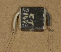
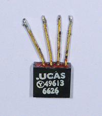
Bridge Rectifier.
Ask anyone with experience repairing SMPSs and they will more often than not tell you to check the capacitors ... which I did, and they all checked out very healthy. I then isolated every transistor and diode ... and they all checked out OK. Then I realised that I hadn't checked out the bridge rectifier. That was because, unlike everything else, it was hidden. I found it loosely clamped to the side of T1, under the chopper board. It was quite a small device (see right), being only about 1cm square. When I examined the wiring to it, I found that the rubber insulation was brick hard. Over-heating maybe? Slightly worrying, there was evidence that some solder had run down one of the legs, inside the rubber insulation, towards the body of the rectifier. The date code on it was for week 26 of 1966. I figured it might be Germanium and not as robust as Silicon but it turns out it is Silicon. Maybe it was time to replace it? After removing the rubber insulation and de-soldering the wires, I checked it and found that one of the four diodes was showing as a low value resistor.
I fitted an 8A bridge rectifier, and since the faulty one had only been loosely attached to the transformer, I chose not to worry about heatsinking ... and who uses a transformer as a heatsink anyway? Bingo! It worked ... no blown Mains fuse ... and a perfectly working RA217D!
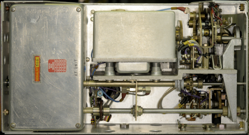
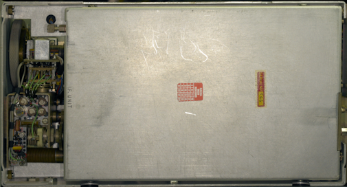
Some photographs of the inside of the RA217D ...
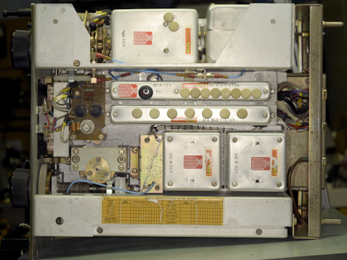
Top View.
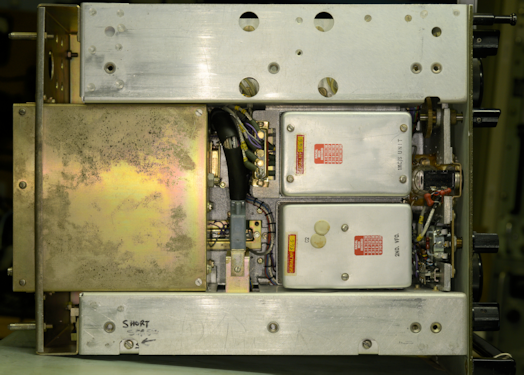
Underside.
RF Unit and 1st VFO.
IF Unit.
On the left is a photograph of the two RA329s. The one on the bottom is the older of the two and the one which had the faulty PSU. It should be added that the RA217D in this one had clearly been giving someone a few headaches. Out of the four main front panel screws, only two were fitted and only one was correct. The IF Unit cover had been removed and when replaced the one short screw was in the wrong place. Thus a long screw was in its place and in danger of causing a short.
I revisited the faulty rectifier and found it to be showing OK on my component analyser ... but I wouldn't trust it.