A High Voltage Bench PSU
17 minute read
November 2026
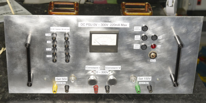 New High-Voltage Power-Supply.
It has been far too long since I had the time to indulge in a personal project. For some time I had thought it would be apt to have a high-voltage bench-power-supply like the one most likely found on test-benches around the RA17 production-line at Racal in Bracknell. I even stumbled across the circuit diagram for this beast in Admiralty Handbook B.R.1171 which identified it as Rack Electrical Equipment Test type PU.156C.
This project was in part inspired by the 'over-the-top' power supply in the Collins R-390, and I liked the idea of using a pair of big 6080 double-triodes in a power-supply for testing RA17, RA117 and MA79 modules ... it just seemed so appropriate.
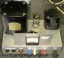
Old HVPSU.
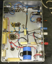
Old HVPSU, inside.
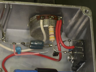
Simple regulator.
For some time now, I have been using a power-supply (above) made from parts taken from a scrapped RA17, which I then modified using the simplest of circuits to make it variable from 0V to whatever that circuit delivers off-load. This 'quick and dirty' PSU has served me well for several years. I even accidentally knocked it off the bench recently and the only damage incurred was a dent in the floor of my workshop!
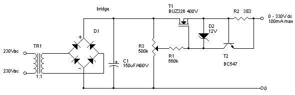 Super-Simple MOSFET Regulator.
The schematic above appears on many websites, usually in response to requests for a method of creating a variable high-voltage power-supply. I first came across this nifty little circuit several years ago, so I will not attempt to claim responsibility and I'm pretty sure that the website I found it on no longer exists. As long as you don't mind the lack of stabilisation, it makes for a reliable no-frills high-voltage variable PSU.
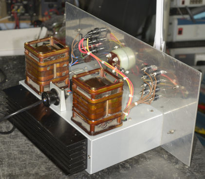
But the urge to build a better and more versatile high-voltage PSU was always there. Then, a few months ago, a good friend gave me a power-supply chassis dating from the early 1960s, comprising a pair of high-quality high-voltage mains transformers and a lovely smoothing choke. Rectification was by multiple series-connected germanium diodes (which I duly replaced with MUR480s) and HT regulation was handled by a pair of CV4079 triodes ... not 6080s, but definitely well on the way to satisfying my desire to build a retro valve-based HVPSU. After refurbishment, which entailed re-stuffing the existing smoothing capacitors, I got the circuit to work but it had one serious draw-back. Although the output voltage was variable, the amount of variance was limited to about 50V around a nominal pre-set voltage. Ideally I wanted to have a power supply which would deliver a voltage which was continuously variable between 0V and at least +250V. The main reason for this was that I don't like nasty surprises. I like being able to slowly 'wind' the HT supply (or B+ line) up from 0V after refurbishing a module. So, I had a look at what I had on Racal's PU156C ...
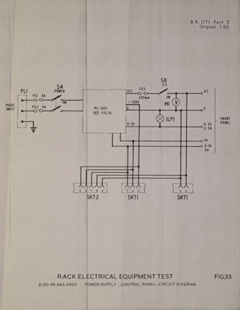
PU156C wiring.
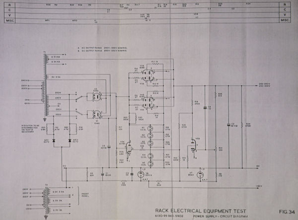
PU156C schematic.
Externally, Racal's PU156C was clearly very simple. Although there is a voltmeter, there is no actual external means of varying the HT voltage. This is actually quite sensible as it means that there is no way the output of the power supply can be interfered with. The schematic for the PSU reveals no less than twelve valves, seven of which are neon stabilisers. Two 5V4Gs with 'strapped' anodes handle the main rectification while a pair of paralleled 6080s deliver the regulated output. Rectifiers MR1 and MR2, identified as type 5D72, provide the basis for the -150V rail. And this is where it gets confusing, as a search for data on the 5D72 almost always turns up datasheets for thermionic rectifiers. However, in this case the 5D72 is believed to be a contact-cooled selenium rectifier manufactured by Westinghouse. Thanks to the UK Vintage Radio Repair and Restoration Forum for this information.
The -150V rail is maintained by V6 (150C4) and a second neon stabiliser, V7 (85A2) ensures that the voltage on the cathode of V5B (ECF80) is kept low ... not above +10V under normal operating conditions. The other half of V5 provides the regulation by controlling the grid voltage on the pair of 6080s. N1 thru' N5 is a stack of five series-connected miniature wire-ended neons which form a 300V clamp, ensuring that the output voltage cannot exceed +300V (nominal).
All very nice and clearly very robust in terms of power output ... However, at any time, the output voltage variance is a nominal 50V ... so NOT what I was looking for, and try as I may, I simply couldn't find any valve-based designs for a high-voltage power-supply to satisfy my requirements. But there was one that I remembered; a laboratory power supply from the 1970s. I had good cause to remember the Farnell E350.
So, a little historical and possibly amusing digression ...
In 1976, that's fifty years ago!, I left school and took a job as a lab-technician at what was then Napier College in Edinburgh, before it became a university. I spent the next three years, to the day, in the department of Electrical and Electronic Engineering. I look back on these days as a very useful apprenticeship during which time I learned about large electrical machines (motors and generators) and designed a little box which turned a common oscilloscope into a spectrum analyser suitable for specific lab experiments.
During the summer holidays, us technicians had the task of calibrating all the test equipment that the students used the rest of the year. We had an interesting range of valve voltmeters and the practice was to take a long bench in one of the 'labs' and wire a bunch of them in parallel for testing. On one particular afternoon I had about a dozen identical Advance voltmeters wired up to a Farnell E350 High-Voltage PSU ... similar, but older than the example below.
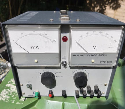
Farnell E350.
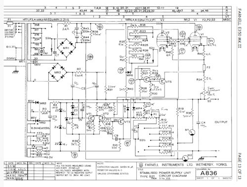
E350 schematic.
A decent power supply it was, but good luck trying to follow that circuit diagram! It looks like rather than being designed, it evolved! However, the E350 has a dark side ... one that us technicians knew and respected. To that effect, on top of the case someone had affixed a warning in red Dymo tape which read
'WARNING, ENSURE OUTPUT SWITCH IS IN OFF POSITION BEFORE SWITCHING OFF MAINS'.
Helping me that afternoon was a student from Rhodesia (this was pre-1980) who was working with us during the summer. I had just finished verifying the accuracy of all the ranges on the voltmeters, starting at the high ranges and working down to the lowest, and had just started removing the leads between the voltmeters. The E350 was on its lowest range (0 - 50V) with the fine control turned fully counter-clockwise, 0V at this point. To save time I was unscrewing the binding posts in pairs, when I heard my 'assistant' announce that he was going to switch off the power supply. I might have been about to tell him to leave it alone. Or maybe I was going to draw his attention to the warning label ... I don't know ... it was irrelevant, I was too late.
Because the next thing I knew, I was on my back on top of the opposite bench and my 'assistant' was laughing hysterically. "You should have seen your face" is all he could say. Of course, I had to draw his attention to the warning label and ask him if he had seen it. Had he perhaps read it? Did it cross his mind that it might be there for a reason? Was I polite? Nope!
We had a small workshop just off that particular lab and the two senior technicians were quickly on the scene. Suffice to say that my 'assistant' got a hell of a roasting and was treated to a demonstration as to the reason for the warning label.
In short, regardless of what range the E350 is set to, or what position the fine control is at, and if the Output switch is left ON when the Mains is switched OFF, then a whopping 800V spike of about 20mS duration appears across the output terminals. I don't know who identified this interesting design feature. It was before my time. But I experienced it first hand. Actually both hands ... the 800V spike was delivered across both hands ... right across my chest. The resulting jolt caused both my arms to fly back with such force that my shoulder blades met in the middle and I went flying across the gap between the benches to land on top of the other one.
How did I feel? Apart from a sharp pain between my shoulder blades, evidenced by the bruise which duly emerged, I felt fine, a tad angry perhaps, but honestly, I felt invigorated. I have been told that the likely reason why my heart had not been stopped was because the heart sits below the straight line between the shoulders. The current did not encroach on my heart. I was very fortunate to say the least.
Was I sent off to hospital to be checked over? Nope! If it happened today, definitely yes, but not fifty years ago. Back then it was a case of nobody died so business as usual. How times change.
... now, back to my HVPSU quest ...
Technically the Farnell E350 does give an output which is variable between 0V and 350V, albeit in seven ranges. And these ranges could easily be made one. But the design is a hybrid of thermionic and solid-state technologies and I was still going for the thermionic approach. So, I went back to the PSU that my friend had given me and continued to trawl the internet for suitable designs.
As well as a variable HT output, I also wanted to have a couple of fixed outputs ... one at +150V and another at -50V. The latter would cater for simulating AGC and RF-Gain control. My current HVPSU had such an output, but by nature of how it was derived (as per the RA17 power supply) it was not fixed ... it was dependent on what the HT was set to ... so, not ideal. The PSU that I had been given had three HT windings over two transformers. These were 270-0-270 at 220mA, 100-0-100 at 50mA and 160V at 24mA. The two centre-tapped windings, I can understand, but the 24mA 160V winding was unusual. I thought it would be ideal for the 150V line, but even with a bridge rectifier and sufficient smoothing, I was struggling to get a 150C2 (0A2) stabiliser to strike. Given the low winding current of 24mA I have to wonder if this was intended for powering Nixie Tubes? The original PSU design also provided a stabilised negative 50V rail but the CV4079 ran uncomfortably hot. So with all this in mind and the fact that I was still unable to track down a suitable valve-based design, I started to look at MOSFETs
I eventually came across this website. Its in German but can be automatically translated. I can't remember where I heard it or read it, but I believe referring to valves as GlassFETs is actually valid as they are both voltage-operated technologies, unlike Bipolar transistors which are more reliant on current. Maybe that was what changed my mind, but I liked the simplicity of the design and I had a generous supply of APT5010LVR MOSFETs. These have a Drain-Source voltage of 500V and a continuous Drain current capability of 47A, so they would be more than sufficient. These are the devices that I have used in the past when implementing the simple regulator circuit mentioned above. I bookmarked the website and refined my search for MOSFET-based high-voltage power-supplies and found this website. Look familiar?
I have to admit that the use of four 470uF capacitors (1880uF) for the main smoothing reservoir in the German design is somewhat excessive. I have always believed that a couple of 33uF capacitors will suffice at high voltages. So I felt ratified when I found that the design described by MVAudiolabs replaced these with a single 680uF capacitor. This is a very slick website run by a HiFi enthusiast who I believe might be based in Lithuania. I decided to build my replacement HVPSU using the artwork from the German website. With regards smoothing capacitors, I decided to take the middle ground and use a couple of 470uF capacitors, simply because I had two.
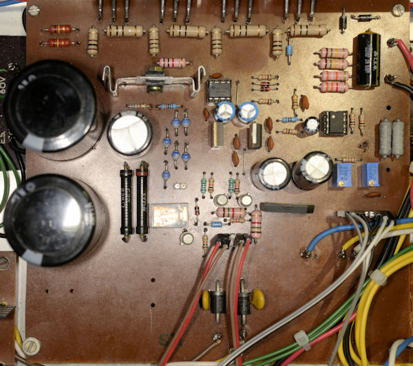
New High-Voltage Power-Supply PCB.
Here there are several deviations from the original. I was able to replace the 4-diode bridge rectifier with a pair of MUR480s since my transformer winding is 270-0-270. Not having a small square-profile bridge rectifier for the low voltage supply, I modified the artwork accordingly to accommodate a suitable in-line bridge rectifier. I didn't have a compatible miniature relay but managed to buy a bunch of similar size 24V relays (without a built in diode across the winding) on Ebay for a song. Again the artwork was modified accordingly. Finally, I replaced the two 15K resistors with a couple of 22K ones simply because I didn't have suitable wattage 15K resistors. The heat sink for the two back-to-back MJE340s was fashioned from a sheet of tin plate. I'm not sure the use of 1W 100-ohm resistors in series with the MOSFET Gates is necessary, but I have a feeling that the smaller ones that I have in abundance are maybe 1/8W, and these I'm sure would not be up for the task, so 1 Watt resistors it is. I assembled the board and using a single MOSFET found that it worked perfectly first time.
I still had to come up with something to provide the -50V and +150 rails. Of course, to make a -ve supply rail, all you need to do is take a standard +ve rail and connect the +ve side to your existing 0V rail. I remember when I worked at Racal, we had a very bright honours student working with us over the summer. We gave him a task which involved a +/- supply and left him to it. By mid afternoon he still hadn't got things together. When asked what was holding him up he said that he couldn't find any negative-voltage power supplies ... bless him!
My plan was to use the two yet unused windings on my mains transformers. The 50mA 100-0-100 winding would be used for the 50V supply, using the same two-diode rectifier as for the main HT supply. The little 24mA 160V winding would be used with an in-line bridge rectifier for the 150V supply. Having spent the better part of a day mulling over various regulator designs, I came across the LR8 High Input-Voltage 3-Terminal Regulator and realised that I had been over-thinking things. This little chip can handle input voltages from +12V up to +450V and provide and output between 1.2V and 440V. The power dissipation is determined by the package style. I was going to use the TO-92 version of the device which has a max dissipation of 0.74W but as I was planning on using a BUZ42 MOSFET as a pass-transistor, the nominal 15mA max output current was not an issue.
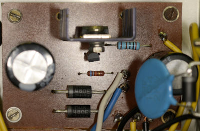
50V regulator board.
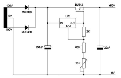
LR8 50V circuit.
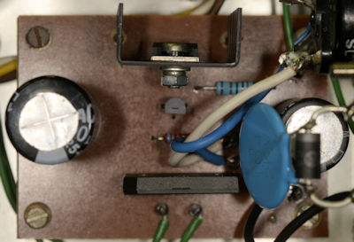
150V regulator board.
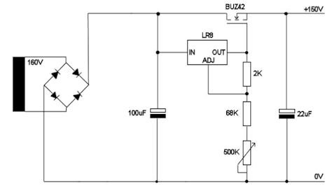
LR8 150V circuit.
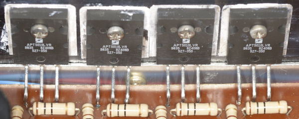 Is this over-kill?
The use of four 500V 47A Power MOSFETs for this power supply may look like a case of over-kill. Maybe it is, but it is worth it. Each device can dissipate 540W!, so that's 2160W in total. Bear in mind that the input voltage after rectification is in excess of 350V and I have limited the maximum output to 300V. Therefore the voltage between the Drain and the Source of each MOSFET can vary between 50V and 350V. So if the current drawn is 200mA, that gives us a power range varying between 10W when the output is set to 300V, and 70W when the output voltage is tending towards 0V. Having said that, I admit that it sounds a bit crazy, after all, how can you have current being drawn when the output voltage is zero? My brain tells me its wrong, but common sense and experience assures me that if there is a voltage drop across the device (and there is) then that is the voltage that must used when calculating the power dissipation. Remember Kirchhoff's Law. This is still within the capability of a single MOSFET, BUT that sort of power will burn your finger. So we spread the power over multiple devices and screw them onto a hefty heat-sink. The 70W is still 70W, but each device is now dissipating only 17.5W. Another benefit of multiple devices that theoretically exists is the reduction of series resistance. Each of these devices has an on-resistance of only 0.1-ohms, but that goes out the window when you stick a 10-ohm power-sharing resistor in series with each Source!
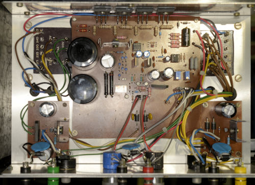
Above: Inside and outside views of the finished power-supply. A fair amount of what went into this project was either salvaged or long-term 'stock'. I can't remember what the box had originally been bought for ... and the front panel, being 19" wide, was clearly originally intended for a rack mounting project. I know the fins on the heat-sink should be vertical, but that was the only heat-sink of suitable size that I had.
The Constant Voltage and Current controls both function. I have limited the maximum voltage to 300V. However there is a minor issue with the Current Limit control. It does work, but the multiturn potentiometer on the board has little effect. I suspect this may be due to the original design being for a 400mA PSU when mine is only 200mA. I still have to create a new scale for the front panel meter.