More on the MA350B
9 minute read
This post is part of the series 'Racal Decade Frequency Generators':
- Decade Frequency Generator Type MA350B
- More on the MA350B
Sept. 2026
To describe the MA350B as extremely complicated and difficult to fault-find on is perhaps a tad cruel. Like the RA17, the MA350B albeit complex, is more clever than complicated. Its construction is modular, and each module can be easily tested individually as long as it remains connected to the rest of the unit.
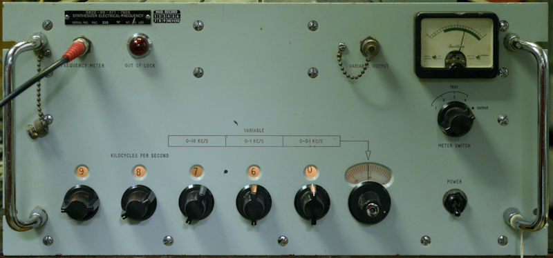
I had an amusing thought today ...'MA350s are like buses ... you don't see any for a while and then along come two at once!'. Its just over a year since I repaired and refurbished an MA350B. Then last month I repaired a rather grubby one. After cleaning much corrosion from the switches etc., I got it up to full spec. Then a couple of weeks ago, I embarked on yet another one ... this time not so grubby, but curiously displaying an identical fault as on the previous one.
The MA350B was designed to work with the MA79 Transmitter Drive Unit and the RA117 Receiver, primarily providing a super-stable and accurate replacement for the KHz VFO.
Other outputs from the MA350B are …
1MHz to replace the 1MHz oscillators in the MA79 and RA117,
200KHz for the MA79H which is fitted with an MA284 mixer,
1.7MHz to replace the 1.7MHz oscillator in the RA117.
There is also a 100KHz output which the manual describes as a carrier re-insertion oscillator for an i.s.b. adapter. I can see how that would work but I’ve NEVER seen it done, since i.s.b adapters like the RA218, RA121 and RA98 all mix the receiver’s 100KHz final IF down to around 18KHz. I suspect this reference to a 'carrier re-insertion oscillator might be something that was written into the design brief, forgotten about, and inadvertently left in the text.
The 100KHz is however used internally by the MA350 to drive the Harmonic Generator in module CHG.
In total there are seven definable modules in the MA350B. These are …
Power Supply providing +12V and -6V, plus a nominally 28V rail (unregulated) for the internal frequency standard.
Internal 1MHz Frequency standard.
Harmonic Generator (module CHG) providing ten spot frequencies between 2.7MHz and 3.6MHz,
Module CRXJ which generates (from the internal or external standard) 100KHz, 200KHz, 300KHz and 1MHz. The Interpolation oscillator is also within this module.
Module CMJ provides a range of frequencies in 100KHz steps between 4.0MHz and 4.9MHz, which is applied to the mixer in the 100KHz decade and 1.7MHz for the RA117. This module also takes the 200KHz from module CRXJ and provides two buffered outputs.
There are two remaining modules which look after the decade selection and final VFO output.
The first of these is module CDDJ/DDJ which provides for the 100Hz and 1KHz decades.
The second is module CDDJ/DJ which provides for the 10KHz and 100KHz decades. This module also includes the output stage for the 3.6MHz- 4.6MHz signal.
For a full technical description of the MA350B, see the technical manual.
As already mentioned, both this MA350B and the one that I repaired a month ago (serial number 119) both exhibited the same curious fault ... the two multi-turn potentiometers on the PSU regulator board were open circuit. In both cases the potentiometers were by Painton, as specified in the items list. However the MA350B that I repaired last year was serial number 359 and the potentiometers, which were still in good condition were manufactured by Bourns. I have to wonder if Racal had identified a weakness in Painton's product and replaced it with one by Bourns.
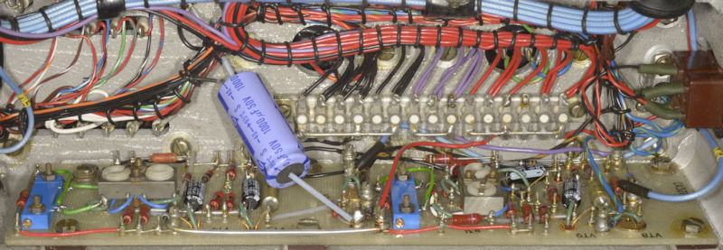
Above: The large 1000uF capacitor replaces the original chassis-mounted one. The four tubular tantalum capacitors have been replaced with aluminium types.
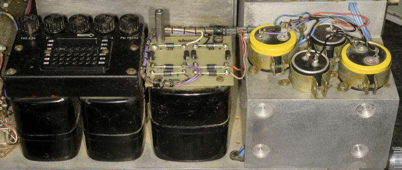
Above: All ten of the original silicon rectifiers have been replaced. The four large electrolytic capacitors have also been re-stuffed with modern aluminium types.Perhaps as a legacy from Racal’s valve-based history, each supply line incorporates a heavy-duty smoothing choke.
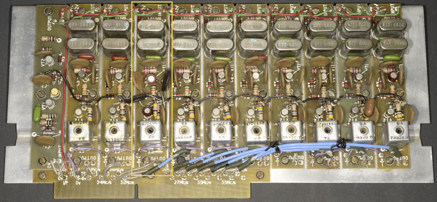
Above: This is module CHG. The Harmonic Generator part is the left-most of the eleven boards. The other ten boards are each tuned to spot-frequencies between 2.7MHz and 3.6MHz. Note the board outlined in yellow. Note also the two transistors each have a red plastic sleeve over them and that there are two additional and more modern capacitors. Although all of the outputs were present and within spec., I was suspicious as to why this one board was different. I discovered that the soft ferrite core in the output transformer was jammed and shattered, likely caused by the use of an incorrect trim tool. The two additional capacitors may have been added in an attempt to increase the output amplitude.
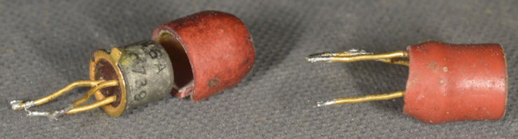
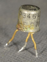
According to the manual, the two transistors should have been Fairchild type C444, but when I removed the plastic shroud from one of them I found it to be a Signetics P346A, which is apparently designated a high speed switching transistor with a modest hfe. Both transistors worked but I replaced them with 2N2222s … everybody’s favourite NPN transistor from the 1980s.
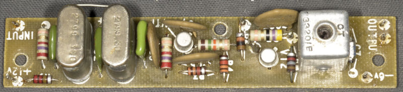
Above: the board with the additional capacitors removed, the 2N2222s fitted and the damaged ferrite core replaced
With the PSU repaired and the CHG module brought up to spec., I was pleasantly surprised to find that the MA350B was almost working. That is to say that I could get all of the decades to ‘lock’ on most of their settings.
As this is my third experience with the MA350B, I have come to have a pretty good feel for the beast. Despite its apparent complexity, it does not intimidate me. In short, each decade is essentially an independent PLL. Once you have confirmed that all the inputs to the four sub-modules (the four decades are split over two modules), a quick test involves use of the front panel meter switch where position 1 is the 100Hz decade, 2 is 1KHz, 3 is 10KHz and 4 is the 100KHz decade.
For any given frequency set, if the red light is on, at least one of the decades will be out of lock. The 100KHz decade is driven by the 10KHz decade which is driven by the 1KHz decade which is driven by the 100Hz decade. Each decade involves a varactor-tuned oscillator which is swept across the valid range of frequencies from the previous decade.
Therefore the obvious starting point is the 100Hz decade, designated 1 on module CDDJ/DDJ. Alignment of the Swept VFO is by way of the adjuster accessible through the hole on the top of the module. Note: the locking nut may need to be first loosened. If the MA350B has not been ‘abused’, it should simply be a case of working through the decades ensuring that lock can be attained at 0 and 9. Ideally this is the only adjustment that should be necessary.
Modules CRXJ and CMJ each involve many tuned circuits, most of which are simple to optimise. However the multi-pole band-pass filter in module CMJ requires a lot of patience and a network analyser should it require re-aligning. My recommendation would be to leave it alone if the output level of the MA350B is within spec. I would liken this filter to the 40MHz BP filter in the RA17 etc. … Misalignment of this filter (4.0MHz – 4.9MHz) can result in ‘holes’ in the pass-band which in turn will result in unwanted amplitude variation of the MA350 main output (3.6MHz – 4.6MHz).
The MA350B allows the user to chose from one of no less than five frequency references. These are as follows …
External references of 5MHz, 1MHz, 200KHz, or 100KHz.
Alternatively, the internal 1MHz reference may be selected. Selection is by way of the switch on the top of module CRXJ.
The 5MHz, 1MHz and 100KHz can be provided by an MA259 Precision Frequency Standard.
The Internal 1MHz reference was originally a Racal type SA.510. This was subsequently replaced with a Sulzer type 1L.
MA350B Serial 339, after refurbishment.
I had an amusing thought today ...'MA350s are like buses ... you don't see any for a while and then along come two at once!'. Its just over a year since I repaired and refurbished an MA350B. Then last month I repaired a rather grubby one. After cleaning much corrosion from the switches etc., I got it up to full spec. Then a couple of weeks ago, I embarked on yet another one ... this time not so grubby, but curiously displaying an identical fault as on the previous one.
The MA350B was designed to work with the MA79 Transmitter Drive Unit and the RA117 Receiver, primarily providing a super-stable and accurate replacement for the KHz VFO.
Other outputs from the MA350B are …
1MHz to replace the 1MHz oscillators in the MA79 and RA117,
200KHz for the MA79H which is fitted with an MA284 mixer,
1.7MHz to replace the 1.7MHz oscillator in the RA117.
There is also a 100KHz output which the manual describes as a carrier re-insertion oscillator for an i.s.b. adapter. I can see how that would work but I’ve NEVER seen it done, since i.s.b adapters like the RA218, RA121 and RA98 all mix the receiver’s 100KHz final IF down to around 18KHz. I suspect this reference to a 'carrier re-insertion oscillator might be something that was written into the design brief, forgotten about, and inadvertently left in the text.
The 100KHz is however used internally by the MA350 to drive the Harmonic Generator in module CHG.
In total there are seven definable modules in the MA350B. These are …
Power Supply providing +12V and -6V, plus a nominally 28V rail (unregulated) for the internal frequency standard.
Internal 1MHz Frequency standard.
Harmonic Generator (module CHG) providing ten spot frequencies between 2.7MHz and 3.6MHz,
Module CRXJ which generates (from the internal or external standard) 100KHz, 200KHz, 300KHz and 1MHz. The Interpolation oscillator is also within this module.
Module CMJ provides a range of frequencies in 100KHz steps between 4.0MHz and 4.9MHz, which is applied to the mixer in the 100KHz decade and 1.7MHz for the RA117. This module also takes the 200KHz from module CRXJ and provides two buffered outputs.
There are two remaining modules which look after the decade selection and final VFO output.
The first of these is module CDDJ/DDJ which provides for the 100Hz and 1KHz decades.
The second is module CDDJ/DJ which provides for the 10KHz and 100KHz decades. This module also includes the output stage for the 3.6MHz- 4.6MHz signal.
For a full technical description of the MA350B, see the technical manual.
As already mentioned, both this MA350B and the one that I repaired a month ago (serial number 119) both exhibited the same curious fault ... the two multi-turn potentiometers on the PSU regulator board were open circuit. In both cases the potentiometers were by Painton, as specified in the items list. However the MA350B that I repaired last year was serial number 359 and the potentiometers, which were still in good condition were manufactured by Bourns. I have to wonder if Racal had identified a weakness in Painton's product and replaced it with one by Bourns.
Repaired and refurbished regulator board.
Above: The large 1000uF capacitor replaces the original chassis-mounted one. The four tubular tantalum capacitors have been replaced with aluminium types.
The fully Refurbished PSU.
Above: All ten of the original silicon rectifiers have been replaced. The four large electrolytic capacitors have also been re-stuffed with modern aluminium types.Perhaps as a legacy from Racal’s valve-based history, each supply line incorporates a heavy-duty smoothing choke.
Module CHG.
Above: This is module CHG. The Harmonic Generator part is the left-most of the eleven boards. The other ten boards are each tuned to spot-frequencies between 2.7MHz and 3.6MHz. Note the board outlined in yellow. Note also the two transistors each have a red plastic sleeve over them and that there are two additional and more modern capacitors. Although all of the outputs were present and within spec., I was suspicious as to why this one board was different. I discovered that the soft ferrite core in the output transformer was jammed and shattered, likely caused by the use of an incorrect trim tool. The two additional capacitors may have been added in an attempt to increase the output amplitude.
Two plastic sleaved transistors.
Signetics P-346A.
According to the manual, the two transistors should have been Fairchild type C444, but when I removed the plastic shroud from one of them I found it to be a Signetics P346A, which is apparently designated a high speed switching transistor with a modest hfe. Both transistors worked but I replaced them with 2N2222s … everybody’s favourite NPN transistor from the 1980s.
Above: the board with the additional capacitors removed, the 2N2222s fitted and the damaged ferrite core replaced
With the PSU repaired and the CHG module brought up to spec., I was pleasantly surprised to find that the MA350B was almost working. That is to say that I could get all of the decades to ‘lock’ on most of their settings.
As this is my third experience with the MA350B, I have come to have a pretty good feel for the beast. Despite its apparent complexity, it does not intimidate me. In short, each decade is essentially an independent PLL. Once you have confirmed that all the inputs to the four sub-modules (the four decades are split over two modules), a quick test involves use of the front panel meter switch where position 1 is the 100Hz decade, 2 is 1KHz, 3 is 10KHz and 4 is the 100KHz decade.
For any given frequency set, if the red light is on, at least one of the decades will be out of lock. The 100KHz decade is driven by the 10KHz decade which is driven by the 1KHz decade which is driven by the 100Hz decade. Each decade involves a varactor-tuned oscillator which is swept across the valid range of frequencies from the previous decade.
Therefore the obvious starting point is the 100Hz decade, designated 1 on module CDDJ/DDJ. Alignment of the Swept VFO is by way of the adjuster accessible through the hole on the top of the module. Note: the locking nut may need to be first loosened. If the MA350B has not been ‘abused’, it should simply be a case of working through the decades ensuring that lock can be attained at 0 and 9. Ideally this is the only adjustment that should be necessary.
Modules CRXJ and CMJ each involve many tuned circuits, most of which are simple to optimise. However the multi-pole band-pass filter in module CMJ requires a lot of patience and a network analyser should it require re-aligning. My recommendation would be to leave it alone if the output level of the MA350B is within spec. I would liken this filter to the 40MHz BP filter in the RA17 etc. … Misalignment of this filter (4.0MHz – 4.9MHz) can result in ‘holes’ in the pass-band which in turn will result in unwanted amplitude variation of the MA350 main output (3.6MHz – 4.6MHz).
The MA350B allows the user to chose from one of no less than five frequency references. These are as follows …
External references of 5MHz, 1MHz, 200KHz, or 100KHz.
Alternatively, the internal 1MHz reference may be selected. Selection is by way of the switch on the top of module CRXJ.
The 5MHz, 1MHz and 100KHz can be provided by an MA259 Precision Frequency Standard.
The Internal 1MHz reference was originally a Racal type SA.510. This was subsequently replaced with a Sulzer type 1L.
Racal SA.510.
SA-510 Innards.
Sulzer (Tracor) 1L.
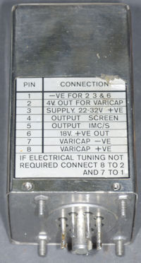
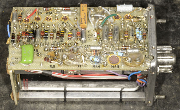
Above and left: This is the internal 1MHz Oscillator as fitted in MA350B Ser. 339. Although there is no identification label, I believe it to be an SA510. Although the output is a beautiful full spec. (Level) sine-wave, it is 15KHz high, the physical adjustment does nothing, neither does the varactor tuning option.
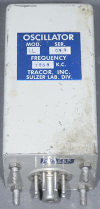
Left: This is an example of the Sulzer (or Tracor) type 1L which ultimately replaced the SA510.
Unfortunately there is zero information (other than the technical brochure, which I have) available on-line on the SA.510. Unlike the Sulzer 1L which is sealed, the SA.510 can be easily opened. The actual oscillator sits within a small glass thermos flask and has no less than eight wires going to it from the board. Close examination of the wiring revealed that someone had been in there before me. Two of the wires are the heater element. The function of remaining six are less easy to identify, although the output lead is fairly obvious, as is 0V. Figuring out how this thing works will be a challenge. There is always the possibility that it might be a copy of the Sulzer 1L, but I will need to find a way into it to verify that.
Left: This is an example of the Sulzer (or Tracor) type 1L which ultimately replaced the SA510.
Unfortunately there is zero information (other than the technical brochure, which I have) available on-line on the SA.510. Unlike the Sulzer 1L which is sealed, the SA.510 can be easily opened. The actual oscillator sits within a small glass thermos flask and has no less than eight wires going to it from the board. Close examination of the wiring revealed that someone had been in there before me. Two of the wires are the heater element. The function of remaining six are less easy to identify, although the output lead is fairly obvious, as is 0V. Figuring out how this thing works will be a challenge. There is always the possibility that it might be a copy of the Sulzer 1L, but I will need to find a way into it to verify that.